Article

Effect of Boron and Iron at Various Concentrations on the Catalytic Graphitization of the Polyacrylonitrile Derived from the Polymerization of Acrylonitrile

1
Department of Nano Convergence Engineering, Jeonbuk National University, Jeonju 561756, Republic of Korea
2
Department of Organic Materials and Textile Engineering, Jeonbuk National University, Jeonju 561756, Republic of Korea
*
Authors to whom correspondence should be addressed.
Inorganics 2025, 13(2), 52; https://doi.org/10.3390/inorganics13020052
Submission received: 4 December 2024 / Revised: 5 February 2025 / Accepted: 5 February 2025 / Published: 11 February 2025
(This article belongs to the Section Inorganic Solid-State Chemistry)

Abstract

In this study, a novel and facile approach of catalytic graphitization was adopted for the preparation of graphitized polyacrylonitrile (PAN)-derived carbon. Pure PAN and boron-introduced PAN were derived from the monomer acrylonitrile using a polymerization technique. Iron nitrate nonahydrate at different concentrations (2.5%, 5%, and 10%) was added to the boronated PAN and carbonized at 1250 °C. The effect of iron and boron on the catalytic graphitization of PAN was comprehensively analyzed. The results showed that the boronated PAN containing a 5% Fe salt was more graphitized due to the optimized amount of the metallic iron, which promoted the rate of conversion of the amorphous carbon to graphitic carbon containing carbon nanotube (CNT) by rearranging the nearby carbon and reducing the energy barrier for the transformation. Furthermore, the in situ formed iron boron carbide within the graphitized carbon provided a nucleation site and stabilized the catalytic activity of the metallic iron at high temperature. This work presents a promising approach for obtaining a highly graphitic PAN-derived carbon by adopting a strategy of catalytic graphitization using the born and iron as catalytic agents.

Graphical Abstract

1. Introduction

Carbon materials are considered not only fundamental to life on Earth but also serve as the ideal materials for the engineering of a wide range of technological applications [1,2,3]. Among the several allotropes of carbon, sp2-bonded graphitic carbon is stable at ambient conditions. This material can potentially be used in various applications such as energy storage and conversion, catalysis, absorption, thermally conductive materials, and various micro- and macro-fabrication techniques [4,5,6,7]. The Earth’s abundant biomass, polymers, and synthetic precursors are the major sources of the graphitic carbons. Among the several possible sources, PAN is one of the prominent sources of graphitic carbon owing to its high carbon yield, high mechanical strength, and good control over structural modifications [8,9]. PAN-based graphitic carbon possesses significant advantages such as being lightweight, having high mechanical strength, and having good thermal and electrical conductivities [10,11,12,13]. Importantly, its extent of thermal and electrical conductivity and tensile modulus is directly affected by the degree of graphitization [14]. Generally, a higher degree of graphitic carbon can be obtained by annealing at higher temperatures [15]. The degree of graphitization can be increased by adding some external catalysts, and this process is known as catalytic graphitization [16,17,18]. This method enables the transformation of non-graphitizing carbon materials into highly graphitized ones, even at reduced annealing temperatures.
Generally, catalytic graphitization can be achieved by transition metals and some heteroatoms such as boron [19]. The heteroatom boron and transition metals such as iron accelerate the extent of graphitization by two mechanisms. Firstly, the disordered carbon dissolves with the added catalysts to form more graphitized carbon, known as the “dissolution–precipitation mechanism”. The second one is the “carbide formation–decomposition mechanism”, in which the amorphous and less ordered carbon interacts with the catalyst to form carbide intermediates [20]. Afterward, the carbide intermediate decomposes to yield the highly graphitic carbon and other byproducts [19].
Boron has one less valence electron than carbon. A limited number of boron atoms can be embedded into the graphitic lattice by a substitution reaction, which alters the microstructure of the material. Thus encapsulated boron atoms increase the electrical conductivity of the carbon material by increasing the carrier density and lowering the Fermi level [10,21,22]. Boron atoms can create local strains in the graphite lattice, which is considered the driving force for accelerating the rate of graphitization [23]. Oya et al. confirmed that 5 and 10% boron promotes the formation of graphitic carbon at a higher temperature [24]. Chen et al. applied the boron catalytic graphitization approach for the production of highly graphitized carbon papers [19]. Boron atoms have the ability to be localized at the less-ordered carbon lattices, which helps the reorientation of the amorphous carbon to the highly ordered and graphitic carbon. This approach also increased the conductivity of the graphitic carbon by up to four times that of graphitic carbon without boron atoms [10]. Hong et al. confirmed that boron can reduce the tunneling distance for inter-CNT and increase the electrical conductivity of the CNT fibers [25]. These previous findings show that the boron doping strategy is a promising approach to preparing a highly graphitic carbon matrix without altering the tensile strength.
Iron-based catalytic graphitization has recently gained attention due to its relatively low graphitization temperature, low cost, and general applicability [26,27,28]. Zhang et al. reported that the graphite degree and electrical conductivity of carbon composite nanofiber greatly increased after the addition of an iron source [29]. Soni et al. synthesized nanocomposite xerogel from powdered precursors, utilizing iron oxide as a catalyst for graphitization. Owing to the above literature, iron is regarded as an effective catalyst for graphitization. To our knowledge, no studies have yet reported on the combined effects of boron and iron for catalytic graphitization of PAN-derived carbon.
Herein, we studied the combined catalytic effect of boron and iron to promote the graphitization of PAN-derived carbon. Both boron and iron independently serve as effective catalysts for enhancing the graphitic structure in carbon materials. Boron alters the lattice microstructure and increases the conductivity, and iron facilitates the graphitization by forming metallic iron and iron boron carbide during carbonization. The results showed that the boronated PAN containing 5% iron salt was found to be highly graphitic owing to the formation of a graphitic chain of carbon nanotubes (CNT) along with metallic iron and iron boron carbide formation. This study provides deep insights into the catalytic roles of boron and iron in enhancing the graphitization degree of PAN-derived carbon, thereby opening pathways to produce high-conductivity, highly graphitized carbon materials for advanced technological applications. Unlike prior studies that utilized these catalysts individually or in less optimized conditions, this research highlights the potential of combining boron and iron to achieve superior graphitization with improved conductivity and structural integrity, thereby paving the way for innovative applications in energy storage, electronics, and other advanced technologies.

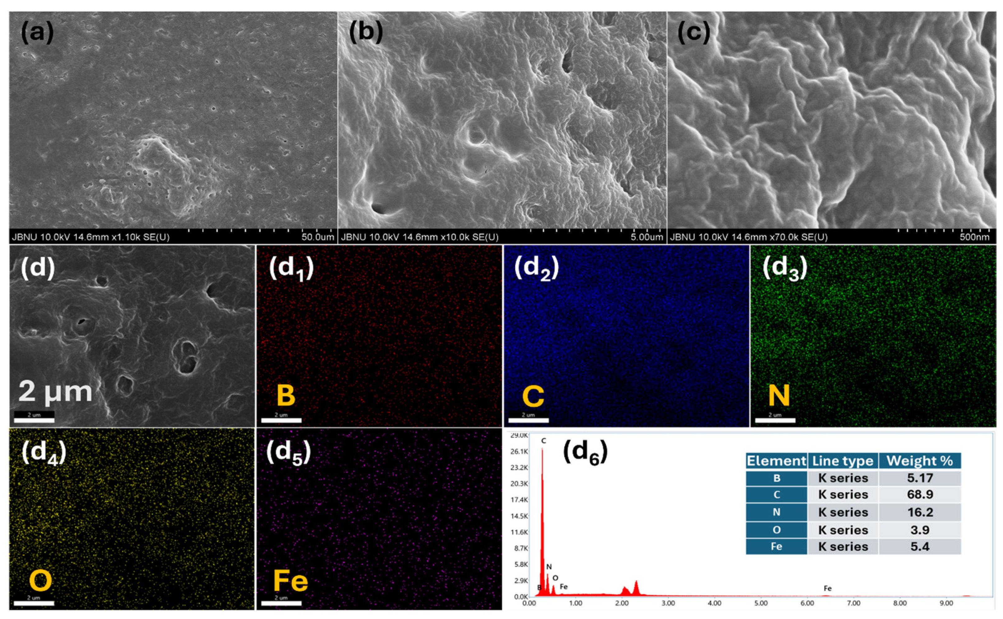
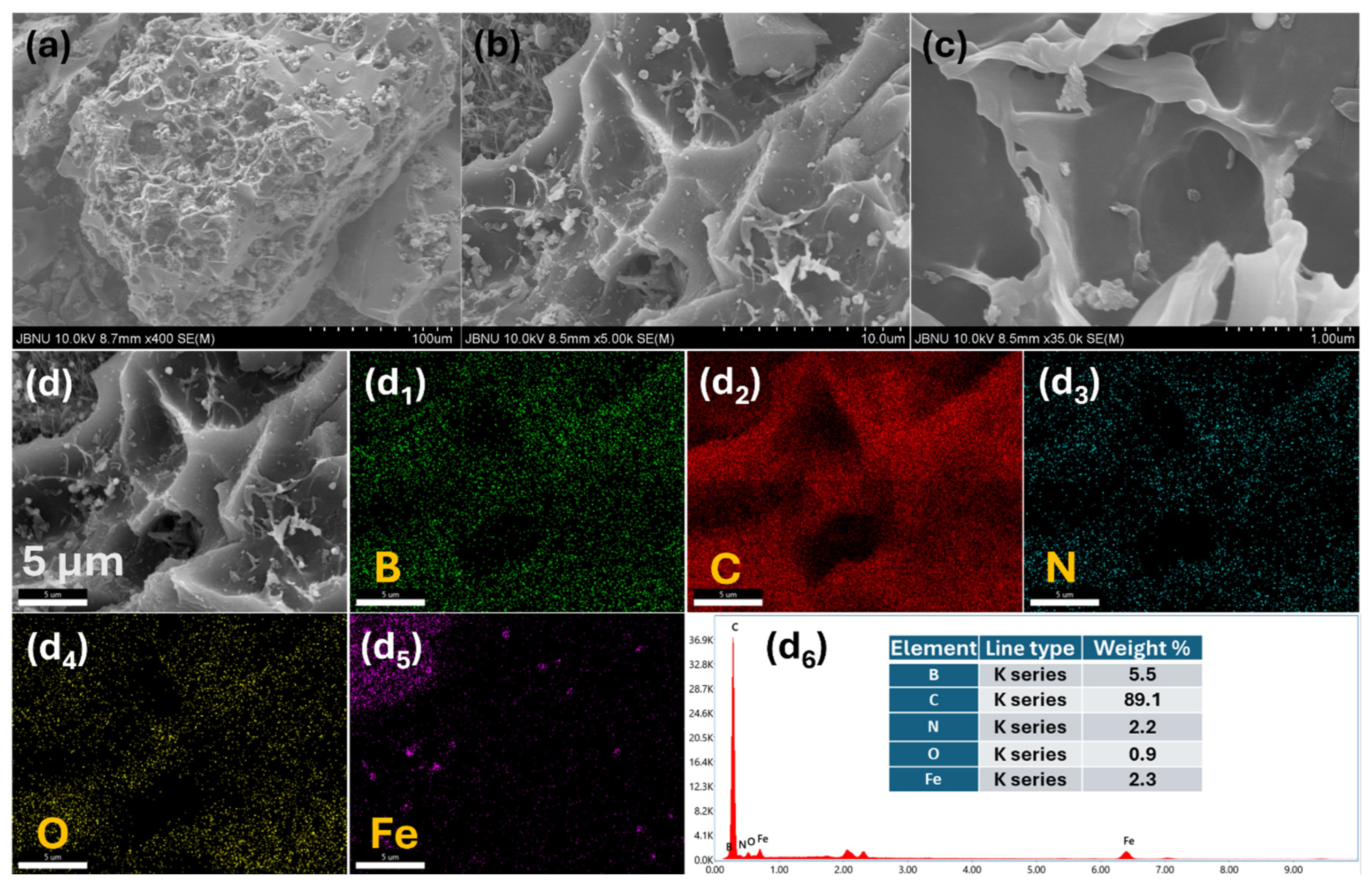
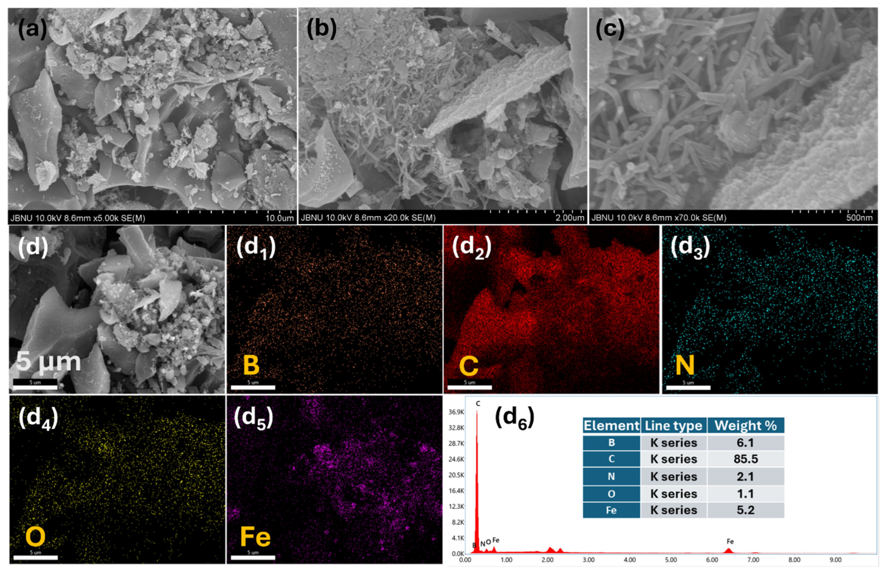
2. Results and Discussion

The schematic representation for the preparation of the boron iron integrated PAN-derived graphitic carbon is presented in Figure 1. Figure 2a–c shows the FESEM images of the PAN-B-Fe5 from lower to higher magnification. The FESEM images indicate that the PAN polymer does not have any distinct orientation or a specific type of morphology. However, the nanoporous and uneven surface is clearly seen in the high-resolution image. The constituent elemental compositions of the PAN were subjected to EDS analysis. As shown in Figure 2(d–d5), B, Fe, C, N, and O are homogeneously distributed in the material. The addition of 5% Fe and B during synthesis was confirmed by the obtained EDS spectrum (Figure 2(d6)). The morphological observations, EDS color mapping images, EDS spectra, and their constituent elemental percentages of the PAN, PAN-B, PAN-B-Fe2.5, and PAN-B-Fe10 are presented in Figures S1–S4, respectively. The low-resolution FESEM image (Figures S1a and S2a) shows that the surface of the PAN and PAN-B is quite smooth with micropores. However, after the incorporation of the iron salt in various concentrations, the porous nature and voids increase due to the defects created by the iron salt in the boronated PAN polymer. Notably, the surface structure of the PAN-B-Fe10 (Figure S4) is highly porous and defective due to the higher concentration of iron salt.
The synthesized polymers PAN, PAN-B, PAN-B-Fe2.5, PAN-B-Fe5, and PAN-B-Fe10 were carbonized in a tubular furnace at 1250 °C for 1 h in an inert atmosphere to study the effect of the boron and iron salt in the graphitization process. The FESEM images of GC-PAN (Figure S5) show no obvious changes in the morphological observations of the surface structure except for the slight nanopores and roughness in the high-resolution image. The morphology of the GC-PAN-B (Figure S6) does not differ from that of GC-PAN, indicating that the boron itself does not actively participate in creating defects and pores in the graphitic PAN. Note that after the incorporation of the iron salt along with the boron source, the morphology of the material drastically changes. As shown in the FESEM image (Figure 3a–c), GC-PAN-B-Fe2.5 is highly porous due to the voids created by the evaporation of the iron and boron. The EDS color mapping images and the EDS spectra of the GC-PAN-B-Fe2.5 are presented in Figure 3(d–d6). Figure 4a–c shows the morphological observations of the GC-PAN-B-Fe5. After increasing the iron nitrate nonahydrate concentration up to 5%, the porosity of the materials is well maintained, and some CNT-like structures are created. During high-temperature carbonization, the iron in the PAN matrix reduces to metallic iron, which catalyzes the formation of the CNT-like graphitic network from the surrounding carbon. Furthermore, the boron and iron in the PAN polymer are converted to iron boron carbide, which has a CNT-like porous structure. Iron in the optimized condition and the boron synergistically work to catalyze the amorphous carbon into the graphitic carbon, in which the boron and iron break and reform the carbon bonds, leading to the formation of a CNT-like graphitic structure. EDS color mapping images (Figure 4(d–d5)) show the homogenous distribution of boron and iron along with the carbon, nitrogen, and oxygen in the GC-PAN-B-Fe5. As shown in the EDS spectrum (Figure 3(d6)), the percentage of carbon increased to 85.5% after carbonization.
Upon increasing the iron concentration up to 10%, the porosity of the carbon materials was well maintained but the CNT-like structure was not observed (Figure 5a–c). The carbon matrix’s voids were greater due to the higher concentrations of iron salt. Notably, GC-PAN-B-Fe10 possesses voids larger than that of the other samples, possibly due to the greater amount of iron evaporated from the carbon network or transformed into iron nanoparticles. As depicted in the FESEM images (Figure 5a–c), iron nanoparticles of average size (400 nm) are clearly observed rather than CNT-like structures. The EDS color mapping and EDS spectrum are shown in Figure 5(d–d6). The EDS color mapping image for iron (Figure 5(d5)) confirms that the obtained granular particles are iron nanoparticles. The nanostructure alterations of graphitic carbon in the high concentration of iron salt are attributed to the following facts: (a) Upon carbonization of the PAN-B-Fe10, the high concentration of the iron tends to aggregate and form larger iron nanoparticles instead of forming homogenous graphitic CNT-like structures. (b) Iron particles tend to cluster together rather than disperse in higher concentrations, which reduces the ability of CNT formation and accelerates the rate of forming iron nanoparticles. (c) Upon carbonization, the high concentration of iron consumes more surrounding carbon, breaking down the continuity of the carbon material required for CNT formation. This leads to the formation of iron nanoparticles embedded in porous carbon. So, the high iron concentration creates meso or macroporous structures, forms iron nanoparticles, and reduces the carbon availability for creating CNTs.
A close analysis of the published literature revealed that the morphology of PAN-derived graphitized carbon varies significantly depending on the graphitization conditions and the type of external catalytic agents used. For instance, Juan et al. (2014) reported a microsphere-type morphology for PAN-derived graphitized carbon [30]. Huang et al. (2021) converted polyacrylonitrile into 2D graphite layers by carbonizing at 2800 °C [31]. Similarly, Begum et al. (2021) synthesized porous carbon nanoballs from polyacrylonitrile through carbonization at 700 °C [32].
The effect of the boron and iron for graphitization of the PAN was also evaluated by Raman analysis. In Figure 6a, intense D and G bands at 1345 cm−1 and 1579 cm−1 correspond to the defect lattice vibration and graphite lattice vibration modes, respectively [33,34], The broad and flattened peak at ~2900 cm−1 represents the stacking order of a graphene-like 2D layer in the material [16]. The ratio of the intensities of the defective and graphitic bands can quantify the degree of the graphitization of the material. The lower the value of ID/IG, the higher the graphitic nature of the material and vice versa. The ID/IG values of GC-PAN, GC-PAN-B, GC-PAN-B-Fe2.5, GC-PAN-B-Fe5, and GC-PAN-B-Fe10 were found to be 0.98428, 0.96106, 0.95235, 0.93271, and 0.89379, respectively. This result shows that GC-PAN-B-Fe5 is highly graphitized. Incorporation of the boron source and iron salt in the optimized condition (5%) leads to the formation of the highly graphitic CNTs with a carbon-to-carbon network, which ultimately increases the graphitic nature of the material.
The successful synthesis of the material was further confirmed by performing XRD analysis. Figure 6b compares the XRD patterns of all the PAN-derived graphitic carbon materials. GC-PAN and GC-PAN-B show almost similar XRD patterns, implying that the boron incorporation does not significantly alter the phase of the material. However, the combination of boron and iron significantly alters the crystallinity of the material. As shown in Figure 6b, the XRD patterns of the GC-PAN-B-Fe2.5, GC-PAN-B-Fe5, and GC-PAN-B-Fe10 are well matched with the iron boron carbide (Fe23(C, B)6, PDF#12-0570) and iron (PDF#06-0696). The intensity of the peaks related to iron boron carbide and iron increases upon increasing the concentration of the iron salt in the material. The intense peaks at 44.44° and 51.75° are due to the (511) and (600) of the iron boron carbide. Similarly, iron nanoparticle (PDF#06-0696) related peaks are observed at 44.67° (110), 65.02° (200), and 82.33° (211). The metallic iron catalyzes the conversion of amorphous carbon to graphitic carbon by promoting carbon rearrangement and reducing the energy barrier for the transformation. The less-ordered carbon reacts with the iron boron carbide and decomposes to give highly graphitic carbon [19]. Furthermore, iron boron carbide provides a nucleation site and helps to stabilize the iron’s catalytic activity at high temperatures. Figure 6c,d show the BET isotherms (nitrogen adsorption–desorption) and BJH pore size distributions of the different samples. The surface area and average pore size of the GC-PAN-B-Fe2.5, GC-PAN-B-Fe5, and GC-PAN-B-Fe10 were found to be 12.4, 16.9 and 13.1 m2 g−1 and 17.06, 21.16 and 18.5 nm, respectively. The enhanced surface area of GC-PAN-B-Fe5 is due to the boron and iron integrated porous graphitic carbon. The TGA analysis results (Figure 7) show that the pristine PAN-GC maintains a constant weight, whereas materials with a higher iron salt content exhibit greater weight loss. The % of weight loss by the iron-containing material follows the trend: GC-PAN-B-Fe2.5 ˂ GC-PAN-B-Fe5 ˂ GC-PAN-B-Fe10. The significant weight loss observed for GC-PAN-B-Fe10 is attributed to the transformation of iron nanoparticles during the thermal process. During carbonization, iron from the iron salt (Fe(NO3)3) is reduced to metallic iron, and at higher concentrations, these nanoparticles may undergo oxidation or evaporation while performing TGA analysis, leading to weight loss [26,35,36]. The weight loss is not directly caused by the graphitization process itself, but rather by the volatilization of the metallic iron or its conversion into a form that is no longer present in the final carbonized material. These results demonstrate that the materials are already graphitized and exhibit high resistance to thermal degradation in a nitrogen atmosphere.
The enhanced graphitization of the PAN-derived carbon materials significantly boosts their performance in key applications such as energy storage devices (e.g., supercapacitors and batteries), electrocatalysis (e.g., fuel cells and water splitting), structural composites, and wastewater treatments. The high degree of graphitization improves their electrical conductivity, thermal stability, and mechanical strength, making them promising candidates for advanced technological applications [37,38,39,40].

3. Materials and Methods

3.1. Chemicals and Reagents

Acrylonitrile (≥99.0%), itaconic acid (≥99.0%), 1-dodecanethiol (≥98.5%), 2,2-azobisisobutylronitrile (KOH, ≥98.0%), and DMSO (≥99.0%) were obtained from Samchun, Republic of Korea. Dibutyl vinylboronate (≥94.0%) was provided by Tokyo Chemical Industry Co. Ltd., Tokyo, Japan. Iron nitrate nonahydrate (Fe(NO3)3 ≥ 98.0%) was purchased from Sigma–Aldrich, St. Louis, MO, USA. All of the chemical compounds were analytical grade and used without further purification.

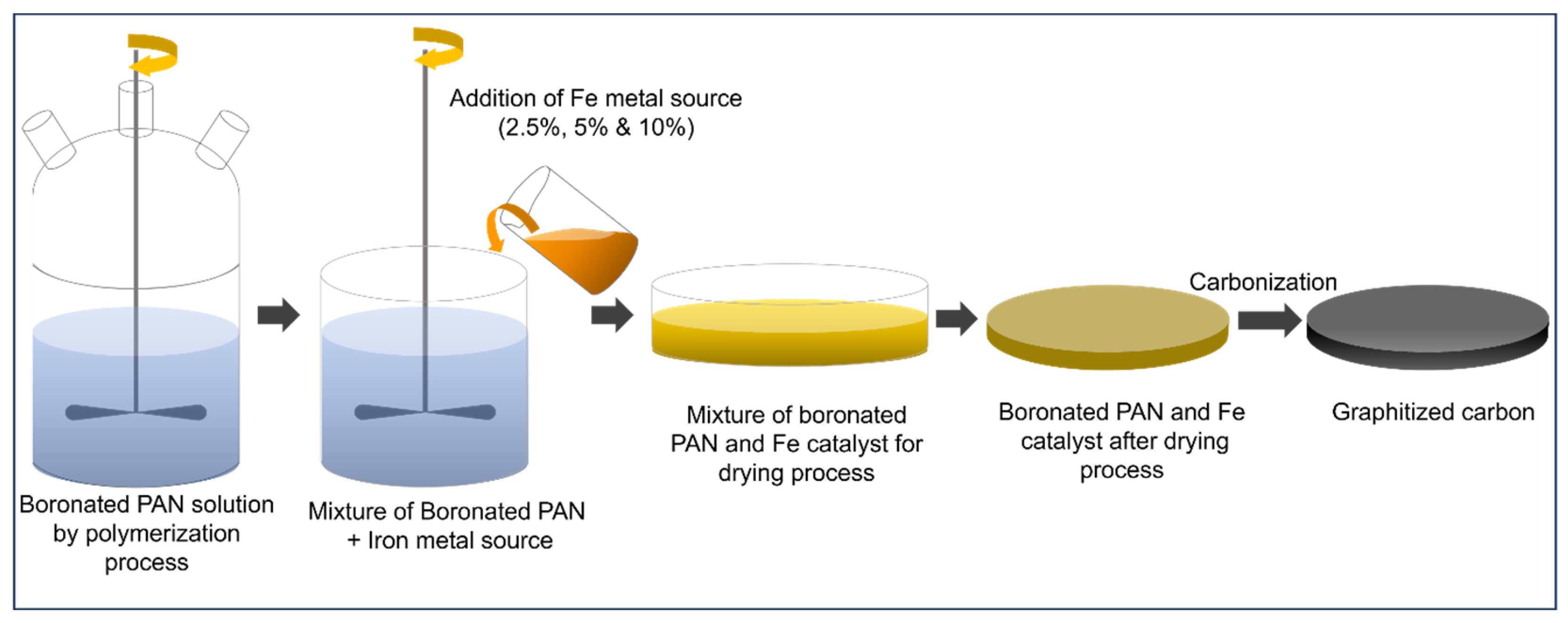
3.2. Preparation of Boron Iron Integrated PAN-Derived Graphitized Carbon (GC-PAN-B-Fe)

Acrylonitrile, 2,2-azobisisobutyronitrile, itaconic acid and 1-dodecanethiol were dissolved in DMSO (100 mL) and vigorously stirred to prepare the PAN polymer. Boron-integrated PAN (PAN-B) was prepared by following a similar process, with the addition of dibutyl vinylboronate during the polymerization process. Furthermore, boron iron integrated PAN (PAN-B-FeX, where X = 2.5%, 5%, and 10%) was prepared by adding a fixed amount of divinyl boronate and iron nitrate solution at different concentrations (2.5%, 5%, and 10%) during the polymerization. The as-prepared polymer solutions were dried in an oven at 60 °C for 12 h. The obtained solidified materials were subsequently carbonized at 1250 °C for 1 h, with a ramping rate of 5 °C/min under a nitrogen atmosphere. The graphitic carbon materials obtained from PAN, PAN-B, PAN-B-Fe2.5, PAN-B-Fe5, and PAN-B-Fe10 were designated as GC-PAN, GC-PAN-B, GC-PAN-B-Fe2.5, GC-PAN-B-Fe5, and GC-PAN-B-Fe10, respectively.

3.3. Material Characterization

The morphology and the constituent elemental compositions of the synthesized materials were studied by field emission–scanning electron microscopy (FESEM; JEOL, JSM-6701F, Tokyo, Japan) equipped with an energy dispersive X-ray spectroscopy (EDS) detector. The phases of the materials were subjected to X-ray crystallographic (XRD) analysis (Rigaku Corporation, Tokyo, Japan), Cu Kα radiation (λ = 1.5406 Å). A Raman spectrometer (RES-100S, Bruker, Billerica, MA, USA, helium-neon laser) was used for studying the degree of graphitization of the material. Thermogravimetric analysis (TGA) (Universal V4 5A TA instrument, SDT Q600, New Castle, DE, USA) of samples was performed in a nitrogen atmosphere from room temperature to 800 °C at a heating rate of 10 °C min−1. The BET surface area and pore size distribution of the materials were evaluated by performing N2 adsorption–desorption using an adsorption analyzer (Micromeritics, 3 Flex 5.00, Norcross, GA, USA).

4. Conclusions

PAN polymer was prepared through its monomer (acrylonitrile) and subjected to carbonization to prepare graphitic carbon. Boron–iron-induced catalytic graphitization was used to prepare the PAN-derived graphitized carbon. The boron and iron salt in the optimized condition (5%) was found to be more highly graphitic than the other samples. The metallic iron and the iron boron carbide formed during the carbonization process promote the extent of graphitization through two processes, the “dissolution–precipitation mechanism” and “carbide formation–decomposition mechanism”. This work provides a promising way for obtaining graphitized PAN-derived carbon, and also offers mechanistic insights into boron–iron catalytic graphitization for producing graphitic carbon.

Supplementary Materials

The following supporting information can be downloaded at: https://www.mdpi.com/article/10.3390/inorganics13020052/s1. Figure S1: (a–c) FESEM images of PAN. EDX analysis results of PAN: (d) elemental mapping area; (d1) superimposition of all elements; elemental color mapping images of (d2) C, (d3) N, (d4) O; and (d5) EDS spectrum with element %. Figure S2: (a–c) FESEM images of PAN-B. EDX analysis results PAN-B: (d) elemental mapping area; (d1) superimposition of all elements; elemental color mapping images of (d2) B, (d3) C, (d4) N, (d5) O; and (d6) EDS spectrum with element %. Figure S3: (a–c) FESEM images of PAN-B-Fe2.5. EDX analysis results in PAN-B-Fe2.5: (d) elemental mapping area; (d1) superimposition of all elements; and elemental color mapping images of (d2) B, (d3) C, (d4) N, (d5) O, and (d6) Fe. Figure S4: (a–c) FESEM images of PAN-B-Fe10. EDX analysis results PAN-B-Fe10: (d) elemental mapping area; (d1) superimposition of all elements; and elemental color mapping images of (d2) B, (d3) C, (d4) N, (d5) O, and (d6) Fe. Figure S5: (a–c) FESEM images of GC-PAN. EDX analysis results GC-PAN: (d) elemental mapping area; (d1) superimposition of all elements; elemental color mapping images of (d2) C, (d3) N, (d4) O; and (d5) EDS spectrum with element %. Figure S6: (a–c) FESEM images of GC-PAN-B. EDX analysis results GC-PAN-B: (d) elemental mapping area; (d1) superimposition of all elements; elemental color mapping images of (d2) B, (d3) C, (d4) N, (d5) O; and (d6) EDS spectrum with element %.

Author Contributions

Conceptualization, T.K. and H.Y.K.; Data curation, B.-S.K. and H.Y.K.; Formal analysis, B.-S.K., T.H.K. and H.Y.K.; Funding acquisition, T.H.K.; Investigation, B.-S.K., T.H.K. and H.Y.K.; Methodology, T.K. and H.Y.K.; Project administration, T.H.K.; Resources, H.Y.K.; Software, B.-S.K.; Supervision, T.H.K. and H.Y.K.; Validation, H.Y.K.; Visualization, T.K.; Writing—original draft, T.K.; Writing—review and editing, T.K. and H.Y.K. All authors have read and agreed to the published version of the manuscript.

Funding

The Korean Research Institute for Defense Technology Planning and Advancement (KRIT) funded by the Korean government (DAPA-Defense Acquisition Program Administration) (Grant No. KRIT-CT-22-025, Ultra-High Modulus Carbon Fiber Research Laboratory) supported this work.

Data Availability Statement

The original contributions presented in this study are included in the article. Further inquiries can be directed to the corresponding author.

Conflicts of Interest

The authors declare no conflicts of interest.

References

  1. Kopeć, M.; Lamson, M.; Yuan, R.; Tang, C.; Kruk, M.; Zhong, M.; Matyjaszewski, K.; Kowalewski, T. Polyacrylonitrile-derived nanostructured carbon materials. Prog. Polym. Sci. 2019, 92, 89–134. [Google Scholar] [CrossRef]
  2. Zhu, W.; Yue, Y.; Wang, H.; Zhang, B.; Hou, R.; Xiao, J.; Huang, X.; Ishag, A.; Sun, Y. Recent advances on energy and environmental application of graphitic carbon nitride (g-C3N4)-based photocatalysts: A review. J. Environ. Chem. Eng. 2023, 11, 110164. [Google Scholar] [CrossRef]
  3. Zhou, X.; Wang, Y.; Gong, C.; Liu, B.; Wei, G. Production, structural design, functional control, and broad applications of carbon nanofiber-based nanomaterials: A comprehensive review. Chem. Eng. J. 2020, 402, 126189. [Google Scholar] [CrossRef]
  4. Maitra, T.; Sharma, S.; Srivastava, A.; Cho, Y.-K.; Madou, M.; Sharma, A. Improved graphitization and electrical conductivity of suspended carbon nanofibers derived from carbon nanotube/polyacrylonitrile composites by directed electrospinning. Carbon 2012, 50, 1753–1761. [Google Scholar] [CrossRef]
  5. Kothandam, G.; Singh, G.; Guan, X.; Lee, J.M.; Ramadass, K.; Joseph, S.; Benzigar, M.; Karakoti, A.; Yi, J.; Kumar, P.; et al. Recent Advances in Carbon-Based Electrodes for Energy Storage and Conversion. Adv. Sci. 2023, 10, 2301045. [Google Scholar] [CrossRef] [PubMed]
  6. He, H.; Zhang, R.; Zhang, P.; Wang, P.; Chen, N.; Qian, B.; Zhang, L.; Yu, J.; Dai, B. Functional Carbon from Nature: Biomass-Derived Carbon Materials and the Recent Progress of Their Applications. Adv. Sci. 2023, 10, 2205557. [Google Scholar] [CrossRef] [PubMed]
  7. Egbedina, A.O.; Bolade, O.P.; Ewuzie, U.; Lima, E.C. Emerging trends in the application of carbon-based materials: A review. J. Environ. Chem. Eng. 2022, 10, 107260. [Google Scholar] [CrossRef]
  8. Lee, S.; Choi, J.; Chung, Y.S.; Kim, J.; Moon, S.; Lee, S. Understanding the catalytic mechanism of calcium compounds for enhancing crystallinity in carbon fiber. Chem. Eng. J. 2024, 479, 147728. [Google Scholar] [CrossRef]
  9. Töngüç Yalçınkaya, T.; Çay, A.; Akduman, Ç.; Akçakoca Kumbasar, E.P.; Yanık, J. Polyacrylonitrile and polyacrylonitrile/cellulose-based activated carbon nanofibers obtained from acrylic textile wastes for carbon dioxide capture. J. Appl. Polym. Sci. 2024, 141, e55475. [Google Scholar] [CrossRef]
  10. Lee, S.; Cho, S.Y.; Chung, Y.S.; Choi, Y.C.; Lee, S. High electrical and thermal conductivities of a PAN-based carbon fiber via boron-assisted catalytic graphitization. Carbon 2022, 199, 70–79. [Google Scholar] [CrossRef]
  11. Zhou, H.; Zhu, J.; Wang, H.-L. Tuning of structural/functional feature of carbon fibers: New insights into the stabilization of polyacrylonitrile. Polymer 2023, 282, 126157. [Google Scholar] [CrossRef]
  12. Tripathy, M.; Padhiari, S.; Ghosh, A.K.; Hota, G. Polyacrylonitrile support impregnated with amine-functionalized graphitic carbon nitride/magnetite composite nanofibers towards enhanced arsenic remediation: A mechanistic approach. J. Colloid Interface Sci. 2023, 640, 890–907. [Google Scholar] [CrossRef] [PubMed]
  13. Xie, Y.; Wang, X. Thermal conductivity of carbon-based nanomaterials: Deep understanding of the structural effects. Green Carbon 2023, 1, 47–57. [Google Scholar] [CrossRef]
  14. Li, A.; Wang, Y.; Zhang, S.; Niu, D.; Guo, B. Study on the mechanical and electrical conductivity properties of waste short carbon fibers concrete and the establishment of conductivity models. J. Build. Eng. 2024, 95, 110296. [Google Scholar] [CrossRef]
  15. Pirabul, K.; Pan, Z.-Z.; Tang, R.; Sunahiro, S.; Liu, H.; Kanamaru, K.; Yoshii, T.; Nishihara, H. Structural Engineering of Nanocarbons Comprising Graphene Frameworks via High-Temperature Annealing. Bull. Chem. Soc. Jpn. 2023, 96, 510–518. [Google Scholar] [CrossRef]
  16. Kim, T.; Kim, B.-S.; Ko, T.H.; Kim, H.Y. Effect of Salt Variability on the Low-Temperature Metal-Catalyzed Graphitization of PAN/DMSO Solutions for the Synthesis of Nanostructured Graphitic Carbon. Inorganics 2024, 12, 212. [Google Scholar] [CrossRef]
  17. Lower, L.; Dey, S.C.; Vook, T.; Nimlos, M.; Park, S.; Sagues, W.J. Catalytic Graphitization of Biocarbon for Lithium-Ion Anodes: A Minireview. ChemSusChem 2023, 16, e202300729. [Google Scholar] [CrossRef] [PubMed]
  18. Farid, M.A.A.; Zheng, A.L.T.; Tsubota, T.; Andou, Y. Catalytic graphitization of biomass-derived ethanosolv lignin using Fe, Co, Ni, and Zn: Microstructural and chemical characterization. J. Anal. Appl. Pyrolysis 2023, 173, 106064. [Google Scholar] [CrossRef]
  19. Chen, L.; Fang, T.; Song, C.; Ju, W.; Li, H.; Hu, J. Boron-Catalytic Graphitization Boosting the Production of High-Performance Carbon Paper at a Moderate Temperature. Adv. Eng. Mater. 2021, 23, 2100305. [Google Scholar] [CrossRef]
  20. Khoshk Rish, S.; Tahmasebi, A.; Wang, R.; Dou, J.; Yu, J. Formation mechanism of nano graphitic structures during microwave catalytic graphitization of activated carbon. Diam. Relat. Mater. 2021, 120, 108699. [Google Scholar] [CrossRef]
  21. Wei, X.; Chen, L.; Gao, S.; Luo, G. Tuning microstructures of polyacrylonitrile-based carbon fibers by catalytic influence of boron for enhancement of mechanical properties and oxidation resistance. Diam. Relat. Mater. 2024, 142, 110758. [Google Scholar] [CrossRef]
  22. Li, J.; Sun, Y.; Jia, X.; Chen, Y.; Tang, Y.; Wan, P.; Pan, J. Boron, oxygen co-doped porous carbon derived from waste tires with enhanced hydrophilic interface as sustainably high-performance material for supercapacitors. J. Energy Storage 2024, 80, 110320. [Google Scholar] [CrossRef]
  23. Shao, Q.; Wang, S.; Yuan, M.; Wang, H.; Jung, J.C.-Y.; Zhang, J. Advanced boron-doped carbon papers with excellent electrical conductivity and low graphitization temperature for PEM fuel cells. Int. J. Hydrog. Energy 2024, 50, 1279–1293. [Google Scholar] [CrossRef]
  24. Ōya, A.; Yamashita, R.; Ōtani, S. Catalytic graphitization of carbons by borons. Fuel 1979, 58, 495–500. [Google Scholar] [CrossRef]
  25. Hong, S.; Nam, J.; Park, S.; Lee, D.; Park, M.; Lee, D.S.; Kim, N.D.; Kim, D.-Y.; Ku, B.-C.; Kim, Y.A.; et al. Carbon nanotube fibers with high specific electrical conductivity: Synergistic effect of heteroatom doping and densification. Carbon 2021, 184, 207–213. [Google Scholar] [CrossRef]
  26. Xia, S.; Yang, H.; Lu, W.; Cai, N.; Xiao, H.; Chen, X.; Chen, Y.; Wang, X.; Wang, S.; Wu, P.; et al. Fe–Co based synergistic catalytic graphitization of biomass: Influence of the catalyst type and the pyrolytic temperature. Energy 2022, 239, 122262. [Google Scholar] [CrossRef]
  27. Hunter, R.D.; Takeguchi, M.; Hashimoto, A.; Ridings, K.M.; Hendy, S.C.; Zakharov, D.; Warnken, N.; Isaacs, J.; Fernandez-Muñoz, S.; Ramirez-Rico, J.; et al. Elucidating the Mechanism of Iron-Catalyzed Graphitization: The First Observation of Homogeneous Solid-State Catalysis. Adv. Mater. 2024, 36, 2404170. [Google Scholar] [CrossRef] [PubMed]
  28. Dyjak, S.; Wyrębska, I.; Błachowski, A.; Kaszuwara, W.; Sobczak, K.; Polański, M.; Gratzke, M.; Kiciński, W. The role of heteroatoms in iron-assisted graphitization of hard carbons derived from synthetic polymers: The special case of sulfur-doping. Carbon 2024, 218, 118717. [Google Scholar] [CrossRef]
  29. Zhang, T.; Huang, D.; Yang, Y.; Kang, F.; Gu, J. Influence of iron (III) acetylacetonate on structure and electrical conductivity of Fe3O4/carbon composite nanofibers. Polymer 2012, 53, 6000–6007. [Google Scholar] [CrossRef]
  30. Jin, J.; Shi, Z.-Q.; Wang, C.-Y. The structure and electrochemical properties of carbonized polyacrylonitrile microspheres. Solid State Ion. 2014, 261, 5–10. [Google Scholar] [CrossRef]
  31. Tian, Y.; An, Y.; Wei, C.; Xi, B.; Xiong, S.; Feng, J.; Qian, Y. Flexible and Free-Standing Ti3C2Tx MXene@Zn Paper for Dendrite-Free Aqueous Zinc Metal Batteries and Nonaqueous Lithium Metal Batteries. ACS Nano 2019, 13, 11676–11685. [Google Scholar] [CrossRef]
  32. Begum, H.; Ahmed, M.S.; Jung, S. Template-free synthesis of polyacrylonitrile-derived porous carbon nanoballs on graphene for efficient oxygen reduction in zinc–air batteries. J. Mater. Chem. A 2021, 9, 9644–9654. [Google Scholar] [CrossRef]
  33. Pathak, I.; Dahal, B.; Acharya, D.; Chhetri, K.; Muthurasu, A.; Raj Rosyara, Y.; Kim, T.; Saidin, S.; Hoon Ko, T.; Yong Kim, H. Integrating V-doped CoP on Ti3C2Tx MXene-incorporated hollow carbon nanofibers as a freestanding positrode and MOF-derived carbon nanotube negatrode for flexible supercapacitors. Chem. Eng. J. 2023, 475, 146351. [Google Scholar] [CrossRef]
  34. Gao, Y.; Wang, J.; Huang, Y.; Zhang, S.; Zhang, S.; Zou, J. Rational design of N-doped porous biomass carbon nanofiber electrodes for flexible asymmetric supercapacitors with high-performance. Appl. Surf. Sci. 2023, 638, 158137. [Google Scholar] [CrossRef]
  35. Xia, S.; Yang, H.; Lei, S.; Lu, W.; Cai, N.; Xiao, H.; Chen, Y.; Chen, H. Iron salt catalytic pyrolysis of biomass: Influence of iron salt type. Energy 2023, 262, 125415. [Google Scholar] [CrossRef]
  36. Tiwari, S.K.; Bystrzejewski, M.; Zhu, Y. Synthesis, properties, and applications of carbon-encapsulated metal nanoparticles. Coord. Chem. Rev. 2024, 520, 216125. [Google Scholar] [CrossRef]
  37. Bisheh, H.; Abdin, Y. Carbon Fibers: From PAN to Asphaltene Precursors; A State-of-Art Review. C 2023, 9, 19. [Google Scholar] [CrossRef]
  38. Kwon, T.-G.; Park, H.; Jo, O.H.; Chun, J.; Kang, B.-G. Facile Preparation of Magnetite-Incorporated Polyacrylonitrile-Derived Carbons for Li-Ion Battery Anodes. ACS Appl. Energy Mater. 2022, 5, 1262–1270. [Google Scholar] [CrossRef]
  39. Gao, Z.; Sanjuán, I.; Hagemann, U.; Wittmar, A.S.M.; Andronescu, C.; Ulbricht, M. Polyacrylonitrile-based porous polymer spheres and their conversion to N-doped carbon materials for adsorption and electrocatalysis. J. Appl. Polym. Sci. 2024, 141, e55438. [Google Scholar] [CrossRef]
  40. Sharma, S.; Basu, S.; Shetti, N.P.; Mondal, K.; Sharma, A.; Aminabhavi, T.M. Versatile Graphitized Carbon Nanofibers in Energy Applications. ACS Sustain. Chem. Eng. 2022, 10, 1334–1360. [Google Scholar] [CrossRef]
Figure 1. Schematic representation of the synthesis of materials.
Inorganics 13 00052 g001
Figure 2. (ac) FESEM images of PAN-B-Fe5. EDX analysis results PAN-B-Fe5: (d) elemental map ping area; elemental color mapping images of (d1) B, (d2) C, (d3) N, (d4) O, and (d5) Fe; and (d6) EDX spectrum with element %.
Inorganics 13 00052 g002
Figure 3. (ac) FESEM images of GC-PAN-B-Fe2.5. EDX analysis results GC-PAN-B-Fe2.5: (d) elemental mapping area; elemental color mapping images of (d1) B, (d2) C, (d3) N, (d4) O, and (d5) Fe; and (d6) EDS spectrum with element %.
Inorganics 13 00052 g003
Figure 4. (ac) FESEM images of GC-PAN-B-Fe5. EDX analysis results GC-PAN-B-Fe5: (d) elemental mapping area; elemental color mapping images of (d1) B, (d2) C, (d3) N, (d4) O, and (d5) Fe; and (d6) EDX spectrum with element %.
Inorganics 13 00052 g004
Figure 5. (ac) FESEM images of GC-PAN-B-Fe10. EDX analysis results GC-PAN-B-Fe10: (d) elemental mapping area; elemental color mapping images of (d1) B, (d2) C, (d3) N, (d4) O and (d5) Fe; and (d6) EDS spectrum with element %.
Inorganics 13 00052 g005
Figure 6. (a) Raman spectra, (b) XRD patterns of different samples, (c) N2 adsorption–desorption isotherms, and (d) BJH pore size distribution plots.
Inorganics 13 00052 g006
Figure 7. TGA curves of various samples.
Inorganics 13 00052 g007
Disclaimer/Publisher’s Note: The statements, opinions and data contained in all publications are solely those of the individual author(s) and contributor(s) and not of MDPI and/or the editor(s). MDPI and/or the editor(s) disclaim responsibility for any injury to people or property resulting from any ideas, methods, instructions or products referred to in the content.

