Abstract
High-performance but expensive neodymium-iron-boron (Nd-Fe-B) magnets are widely used in automotive and electrical applications. Prospective candidates for rare-earth-free magnets include Fe-based magnets such as L10-FeNi and α″-Fe16N2 phase. However, these rare-earth-free magnets cannot replace Nd-Fe-B magnets due to their lower coercivity. Thus, the development of Sm-based magnets, using the relatively abundant rare-earth element Sm, has become a focus of attention. A promising, cheaper alternative with excellent magnetic properties is the Samarium-iron-nitride (Sm-Fe-N) magnet. This paper describes the production and magnetic properties of Sm-Fe-N powders with Th2Zn17 and TbCu7 phases. The production process and magnetic properties of Sm-Fe-N bonded magnets prepared from the powders are also described. Current approaches for producing Sm-Fe-N sintered magnets are included.
1. Introduction
The industrial use of high-performance Nd-Fe-B magnets is expanding rapidly in automotive, industrial, and electrical applications [1,2,3]. The high demand for Nd-Fe-B magnets has raised concerns over their price and the availability of rare earth elements. These severe concerns have led to the study of alternative permanent magnets, which contain fewer or no rare-earth elements.
2. Materials
Prospective candidates for rare-earth-free magnets include manganese-based and iron-based magnets. Mn-based magnets are already produced commercially [4]. Mn-based magnets, such as Mn-Bi magnets with a low-temperature phase and Mn-Ga magnets with a D022 phase, have gained attention [5,6,7,8,9,10,11,12,13,14]. The advantage of the Mn-based magnets is their high anisotropy constant, which indicates high coercivity [15,16,17,18,19,20,21]. However, a problem with Mn-based magnets is their relatively low saturation magnetization, which prevents the creation of high-performance Mn-based magnets [22].
2.1. Rare-Earth-Free Iron-Based Magnets
High-performance Nd-Fe-B magnets are composed of the Nd2Fe14B phase, which has a large saturation magnetization (4πMs), a high anisotropy constant (K1), and a high Curie temperature (Tc) [23]. Table 1 compares these magnetic properties of L10-FeNi and α″-Fe16N2 phases with those of the Nd2Fe14B phase [24,25]. Table 1 compares these magnetic properties of L10-FeNi and α″-Fe16N2 phases with those of the Nd2Fe14B phase.

Table 1.
Intrinsic magnetic properties of L10-FeNi and α″-Fe16N2.
The L10-FeNi phase (tetrataenite) is found in iron meteorites [26]. This phase has a face-centered tetragonal (fct) structure, characterized by high saturation magnetization and a high Curie temperature [27,28]. Although the anisotropic constant of the L10-FeNi phase is smaller than that of the Nd2Fe14B phase, it is high enough to be a permanent magnet. Thus, the L10-FeNi phase is an ideal alternative for Nd-Fe-B magnets. Since the L10-FeNi phase forms naturally at an extremely slow cooling rate of 1 K/106 years in iron meteorites, it cannot be easily obtained by conventional solidification techniques. Recently, a new method for its production, named the NITE (nitrogen insertion and topotactic extraction) method, has been developed [29]. The method involves two steps: first, the nitriding of the FeNi phase to form the FeNiN phase, and then the denitriding of the FeNiN phase to the L10-FeNi phase. The obtained L10-FeNi powder possesses a high saturation magnetization of 1.45 T and a coercivity of 140 kA/m [30].
Among rare-earth-free magnets, the α″-Fe16N2 phase is the most promising candidate, since the nitrogenation of Fe can prepare it. The α″-Fe16N2 phase has a body-centered tetragonal (bct) structure with an extremely high saturation magnetization, significantly higher than that of the Nd2Fe14B phase [31]. The anisotropy constant of the α″-Fe16N2 phase is smaller than that of the Nd2Fe14B phase but is comparable to that of the L10-FeNi phase. Its Curie temperature is higher than that of the Nd2Fe14B phase [32]. Thus, the α″-Fe16N2 phase is also an ideal alternative for Nd-Fe-B magnets. Although this high saturation magnetization was first reported in 1972 [33], it was not confirmed until the α″-Fe16N2 phase with a high saturation magnetization was reproduced in 1991 [34]. The α″-Fe16N2 phase is metastable and thus cannot be obtained by conventional techniques. It is formed by the following reaction: nitrogenation (α-Fe phase → γ-FeN phase), quenching (γ-FeN phase → α’-FeN phase), and long tempering (α’-FeN phase → α″-Fe16N2 phase) [35]. However, it is not possible to obtain pure α″-Fe16N2 phase in this way because the solubility of N in the γ-FeN phase is less than the required concentration (12.5 at %). Thus, studies of the α″-Fe16N2 phase have used various thin-film processing techniques [36,37,38,39]. α″-Fe16N2 powders have been produced by chemical synthesis [40,41]. Powder was produced by a reduction in nano-sized α-Fe2O3 powders, followed by nitriding. It had a high saturation magnetization of 2.18 T at 5 K and a magnetocrystalline anisotropy constant of 0.96 MJm−3 [40]. Powder prepared by chemical synthesis exhibited a high saturation magnetization of 1.57 T, along with a coercivity of 208 kA/m [42]. The problem with Fe-based magnets is the relatively low coercivity. Although Fe-based magnets cannot replace Nd-Fe-B magnets, they can serve as gap magnets, making them suitable substitutes for Nd-Fe-B magnets in certain applications that do not require high coercivity [43]. Therefore, the development of new permanent magnets with high coercivity but without costly rare-earth elements has become a research focus.
2.2. Sm-Based Magnets
Although some rare-earth-free magnets exhibit high saturation magnetization, their performance is expected to be inferior to that of Nd-Fe-B magnets due to their lower coercivity. Therefore, the development of permanent magnets using rare-earth elements is crucial. In practice, Nd-Fe-B magnets are not suitable for motors due to their lower coercivity; instead, Nd-Dy-Fe-B magnets, which incorporate Dy to enhance coercivity, are used. The primary issue with the rare-earth market is the extremely short supply of Dy [44]. Despite their name, rare-earth elements are not rare: cerium (Ce), lanthanum (La), neodymium (Nd), and yttrium (Y) are actually more common in Earth’s crust than lead. The rare-earth elements are defined as a group of 17 elements with similar chemical properties, making it difficult to separate them from one another chemically. So, because it is not easy to obtain a particular rare-earth element directly from its ores, various rare-earth elements are simultaneously obtained by refining ores. Currently, there is an enormous surplus of Ce, Y, and Sm in the rare-earth market [45].
Thus, the development of Sm-based magnets, using the relatively abundant rare-earth element Sm, has become a focus of attention. Studies on Sm-based magnets have focused on SmFe12 and Sm2Fe17N3 [46,47,48]. Both compounds have magnetocrystalline anisotropies and saturation magnetizations comparable to those of the Nd2Fe14B phase (Table 2).

Table 2.
Intrinsic magnetic properties of SmFe12 and Sm2Fe17N3.
The SmFe12 phase has a tetragonal structure (ThMn12-type) with a high saturation magnetization comparable to that of the Nd2Fe14B phase [48,49]. Although its anisotropy constant and Curie temperature are slightly smaller than those of the Nd2Fe14B phase, they are high enough to make it permanently magnetic. As the SmFe12 phase is metastable, its formation is difficult, and only SmFe12 sputtered films have been reported [50,51]. As a result of intensive research on the SmFe12 phase, the substitution of small amounts of Ti for Fe in the SmFe12 phase stabilized the SmFe12 phase as the Sm(Fe,Ti)12 phase [52,53,54,55].
Although the substitution of the non-magnetic Ti for Fe in the SmFe12 phase, as the SmFe11Ti phase, leads to a slight increase in the anisotropy constant and Curie temperature, it significantly decreases the saturation magnetization (Table 3). Further work is underway to improve the magnetic properties of the SmFe12-based phase [56,57].

Table 3.
Intrinsic magnetic properties of SmFe12 and SmFe11Ti.
Up to now, the Sm2Fe17N3 phase has been the most promising candidate, since its saturation magnetization is comparable to that of the Nd2Fe14B phase [46]. In addition, its anisotropy constant and Curie temperature are higher than those of the Nd2Fe14B phase. The details of the Sm2Fe17N3 phase are discussed in the following section.
3. Sm-Fe-N Magnets
Two types of Sm-Fe-N phases have been produced: the Sm2Fe17N3 phase and the SmFe7N phase [46,58,59,60,61,62,63]. The Sm2Fe17N3 phase is obtained by the nitrogenation of Sm-Fe powder with the Th2Zn17 phase, while the SmFe7N phase is obtained by the nitrogenation of Sm-Fe melt-spun ribbon with the TbCu7 phase. The basic difference between the two phases is the crystal structure: the Th2Zn17 phase is rhombohedral, and the TbCu7 phase is hexagonal (Figure 1).
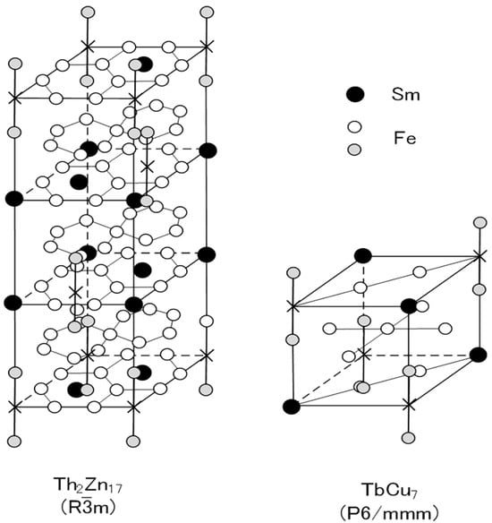
Figure 1.
Schematic diagrams of Th2Zn17 (rhombohedral:R
m) and TbCu7 (hexagonal:P6/mmm) structures. In the Sm-Fe-N magnets, N atoms occupy interstitial sites in the Sm plane of the Th2Zn17 and TbCu7 structures [64].
3.1. Sm-Fe-N Powder
In the production of the Th2Zn17-type Sm-Fe-N powder (Figure 2), the starting materials are Sm2O3 and Fe powders. Sm2Fe17 powder is obtained by the reduction–diffusion (RD) process, during which the Sm2O3 powder is reduced to Sm metal by Ca, and the Sm diffuses into the Fe powder to form Sm2Fe17 powder. The product is washed and rinsed to remove the CaO formed during the RD process. After the nitrogenation of the Sm2Fe17 powder, the resultant Sm2Fe17N3 powder is pulverized finely [65,66,67]. It consists of the Th2Zn17 phase (Figure 3a), with an average particle size of about 3 μm (Figure 4a).
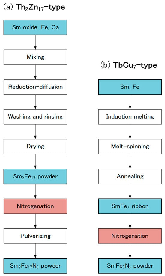
Figure 2.
Production flows of (a) Th2Zn17-type and (b) TbCu7-type Sm-Fe-N powders.
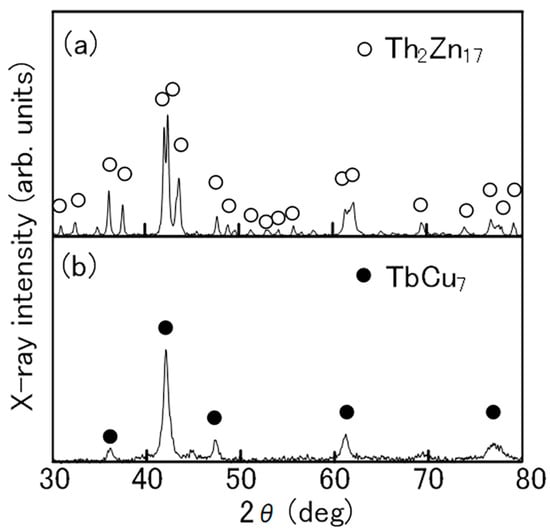
Figure 3.
X-ray diffraction patterns of (a) Th2Zn17-type and (b) TbCu7-type Sm-Fe-N powders [64].
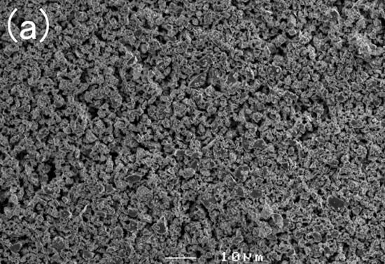
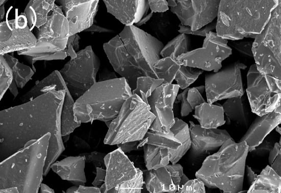
Figure 4.
External appearances of (a) Th2Zn17-type and (b) TbCu7-type Sm-Fe-N powders [64].
Another RD process is used to obtain fine Sm2Fe17 powder without pulverization [68,69,70]. In this process, a sulfuric acid solution containing Sm3+, Fe2+, and SO42−, is used as a starting material. Sm-Fe hydroxide is first obtained by co-precipitation from the sulfuric acid solution, and then pyrolysis of it forms Sm-Fe oxide. Mixtures of fine Sm2Fe17 and CaO powders are produced from the Sm-Fe oxide by the RD process. After the nitrogenation of the mixtures, the CaO is removed from the fine Sm2Fe17N3 powder by washing with water.
In the production of the TbCu7-type Sm-Fe-N powder, the starting materials are Sm and Fe metals [62,71]. The powder is prepared through rapid solidification processing, typically using the melt-spinning technique. The Sm and Fe metals are induction melted, and the resultant SmFe7 alloy is rapidly solidified into SmFe7 ribbon by melt-spinning. Annealing and subsequent nitrogenation of the SmFe7 ribbon produces the SmFe7Nx ribbon, which is then crushed into a coarse powder. It consists of the TbCu7 phase (Figure 3b), with an average particle size of about 20 μm (Figure 4b).
The hysteresis loops of the Th2Zn17-type and TbCu7-type Sm-Fe-N powders are shown in Figure 5. The hysteresis loops of the Th2Zn17-type and TbCu7-type Sm-Fe powders, before nitrogenation, are also shown in Figure 5 for comparison. The loops are evaluated under the applied magnetic field of 2 MA/m after the powders are embedded in paraffin. Since the Th2Zn17-type Sm-Fe-N powders are anisotropic, they were magnetically aligned before being embedded in paraffin for evaluation under an applied magnetic field of 2 MA/m. The narrow hysteresis loops of the Sm-Fe powders (before nitrogenation) indicate that their coercivity values are small. However, the Sm-Fe-N powders have wide hysteresis loops with high coercivity. This confirms that the nitrogenation of the TbCu7-type and Th2Zn17-type Sm-Fe powders significantly increased coercivity.
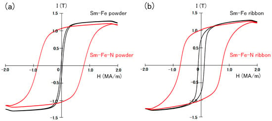
Figure 5.
Hysteresis loops of (a) Th2Zn17-type and (b) TbCu7-type Sm-Fe-N powders, measured under an applied magnetic field of 2 MA/m after the powders were embedded in paraffin [64].
The thermomagnetic curve of the Th2Zn17-type Sm-Fe-N powder clearly shows the Curie temperature (Tc) of the Sm–Fe–N phase (Figure 6a). That of the TbCu7-type Sm-Fe-N powder is almost the same (Figure 6b). The increase in magnetization at high temperatures above 800 K is noted in the thermomagnetic curve of the Th2Zn17-type Sm-Fe-N powder. The observed increase in the thermomagnetic curve is due to the formation of the ferromagnetic phase during the thermomagnetic measurement. The Curie temperature of the ferromagnetic phase is near 1050 K, corresponding to the Curie temperature of the α–Fe phase. The increase is also noted in the thermomagnetic curve of the TbCu7-type Sm-Fe-N powder. It is believed that the α–Fe phase is formed by the decomposition of the Th2Zn17-type and TbCu7-type Sm-Fe-N phases at high temperatures [72].
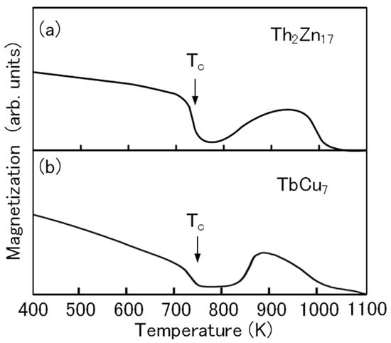
Figure 6.
Thermomagnetic curves of (a) Th2Zn17-type and (b) TbCu7-type Sm-Fe-N powders [64].
The magnetic properties of the Th2Zn17-type and TbCu7-type Sm-Fe-N powders are summarized in Table 4. The Th2Zn17-type Sm-Fe-N powder is commercially prepared by the RD process, while the TbCu7-type Sm-Fe-N powder is commercially prepared by melt-spinning. Since the Th2Zn17-type Sm-Fe-N powder is prepared from the Sm oxide, the production of the Th2Zn17-type Sm-Fe-N powder is less costly than that of the TbCu7-type Sm-Fe-N powder. Both Th2Zn17-type and TbCu7-type Sm-Fe-N powders show excellent magnetic properties: high remanence magnetization, high intrinsic coercivity, and high Curie temperature. Since the Th2Zn17-type Sm-Fe-N powder is anisotropic, it has a higher remanence value than the TbCu7-type Sm-Fe-N powder.

Table 4.
Magnetic properties of Th2Zn17-type and TbCu7-type Sm-Fe-N powders.
In recent years, studies have focused on improving the magnetic properties, especially the coercivity, of Sm-Fe-N powder [73,74,75,76]. It has been reported that Sm-Fe-N powder produced by a polymerized-complex reduction–diffusion process had a high coercivity of 1.84 MA/m [73] and fine Sm-Fe-N powder made by a surfactant-assisted grinding method had a high coercivity of 1.4 MA/m [74]. Since the oxidation of Sm-Fe-N powder reduces the coercivity, Sm-Fe-N powder with a low oxygen content has high coercivity [75,76]. Such high-performance Sm-Fe-N powder will be available soon.
3.2. Sm-Fe-N Bonded Magnets
Magnets are either bonded or sintered. Bonded magnets are widely used as permanent magnets. The first application of Sm-Fe-N powder is in bonded magnets [65,66], which are suitable for mass production owing to their complex shapes and precise sizes, all of which can be achieved without machining.
Sm-Fe-N bonded magnets are usually produced by compression molding or injection molding. In compression molding, Sm-Fe-N powder, thermosetting resin, and an additive are mixed (Figure 7). The typical thermosetting resin is epoxy, and the additive is a coupling agent. The compound is compression-molded and then cured. In injection molding, Sm-Fe-N powder, thermoplastic resin, and an additive are kneaded together. The typical resin is polyamide (PA). The compound is then injection-molded. A magnetic field is applied during both molding processes when producing anisotropic bonded magnets.
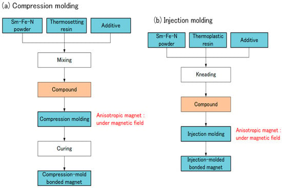
Figure 7.
Production of Sm-Fe-N bonded magnets: (a) compression molding; (b) injection molding.
The magnetic properties of a bonded magnet are determined mainly by the volume fraction and the magnetic properties of the Sm-Fe-N powder. Both anisotropic and isotropic Sm-Fe-N bonded magnets are available from Japanese and Chinese manufacturers. Their typical magnetic properties are listed in Table 5.

Table 5.
Magnetic properties of Sm-Fe-N bonded magnets.
As well as thermosetting or thermoplastic resin, metals and alloys have been tested as the adhesive in Sm-Fe-N bonded magnets. Among low-melting-point metals, zinc proved to be a good metal adhesive [77,78,79,80]. Since then, metal-bonded Sm-Fe-N magnets have been intensively studied (Table 6). Recently, high-performance metal-bonded Sm-Fe-N magnets with a (BH)max of 206 (kJ/m3) have been achieved [80].

Table 6.
Development of metal-bonded Sm-Fe-N magnets.
3.3. Sm-Fe-N Sintered Magnets
As Sm-Fe-N bonded magnets consist of Sm-Fe-N powder and a substantial amount of nonmagnetic binders, their magnetic properties are inferior to those of the fully dense, sintered Sm-Fe-N magnets. Thus, several efforts have been made to produce Sm-Fe-N sintered magnets.
In the Nd-Fe-B sintered magnets, Nd-Fe-B powder is cold-pressed into a compact and then sintered and subsequently annealed at high temperature [25] (Figure 8). However, the same procedure cannot be applied to the Sm-Fe-N sintered magnets, because the Sm-Fe-N phase decomposes into the α-Fe and SmN phases during sintering [72]. Thus, a SmFeN sintered magnet has yet to be realized.
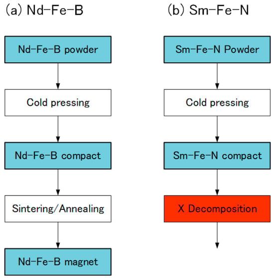
Figure 8.
Production of (a) Nd-Fe-B and (b) Sm-Fe-N magnets.
Figure 9 presents current approaches to the production of Sm-Fe-N magnets. Novel production techniques, such as cold pressing and low-temperature sintering, have been employed to prevent the decomposition of the Sm-Fe-N phase. In cold pressing, the Sm-Fe-N powder is consolidated into bulk magnets at room temperature. In low-temperature sintering, the powder is sintered at temperatures lower than its decomposition temperature.
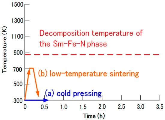
Figure 9.
Approaches to the production of Sm-Fe-N magnets: (a) cold pressing and (b) low-temperature sintering.
Table 7 describes the production of the Sm-Fe-N sintered magnets. In cold pressing, Sm-Fe-N magnets have been produced by dynamic compaction [84,85] or by the compression shearing method [86]. In the dynamic compaction, Sm-Fe-N powders have been consolidated into bulk materials at room temperature by a shock wave, produced by an explosion [84] or a gun method [85]. On the other hand, Sm-Fe-N powders have been consolidated into bulk materials at room temperature by the application of the shear stress to the powder in the compression shearing method. Cold-pressing techniques have yielded high-density Sm-Fe-N magnets. However, these nonconventional techniques cannot be applied to the mass production of Sm-Fe-N magnets.

Table 7.
Techniques used in the production of Sm-Fe-N sintered magnets.
Sm-Fe-N magnets have been obtained by low-temperature sintering techniques, such as high-pressure compaction [87], hot isostatic pressing (HIP) [88], spark plasma sintering (SPS) [89,90,91], and hot rolling, a new consolidation technique [92]. High-density Sm-Fe-N magnets have been produced by applying a high pressure of 1.2 GPa at a low temperature of 673 K for 60 s in the high-pressure compaction [87], and those have been produced by applying an isostatic pressure of 200 MPa at a low temperature of 723 K for 0.5 h in the HIP process [88]. Those have also been produced by applying a pressure of 100 MPa at a low temperature of 673–773 K for 300 s in the SPS process [89,90,91]. The mass production of Sm-Fe-N magnets has good prospects with such advances in manufacturing techniques.
4. Conclusions
In this paper, the magnetic properties of several compounds, L10-FeNi, α″-Fe16N2, SmFe12, SmFe11Ti, and Sm2Fe17N3 phases are compared. The Sm2Fe17N3 phase is revealed as the most promising candidate for the manufacture of Nd-Fe-B magnets. There are two types of Sm-Fe-N magnets: produced from Th2Zn17-type and TbCu7-type Sm-Fe-N powders. The former is produced by the nitriding of Sm2Fe17 powder prepared by reduction-diffusion. The latter is produced by the nitriding of SmFe7 powder prepared by melt spinning. Both Sm-Fe-N powders are successfully processed into bonded magnets with excellent magnetic properties. Despite numerous studies, the production of Sm-Fe-N sintered magnets is still in development. Several new studies have been made for the Sm-Fe-N magnets [93,94,95].
Funding
This research received no external funding.
Data Availability Statement
No new data were created or analyzed in this study.
Conflicts of Interest
The author declares no conflicts of interest.
References
- Bailey, G.; Mancheri, N.; Van Acker, K. Sustainability of permanent rare earth magnet motors in (H)EV industry. J. Sustain. Metall. 2017, 3, 611–626. [Google Scholar] [CrossRef]
- Sreenivasulu, K.V.; Srikanth, V.V.S.S. Fascinating magnetic energy storage nanomaterials: A brief review. Recent Pat. Nanotechnol. 2017, 11, 116–122. [Google Scholar] [CrossRef]
- Yue, M.; Zhang, X.Y.; Liu, J.P. Fabrication of bulk nanostructured permanent magnets with high energy density: Challenges and approaches. Nanoscale 2017, 9, 3674–3697. [Google Scholar] [CrossRef]
- Ohtani, T.; Kato, N.; Kojima, S.; Kojima, K.; Sakamoto, Y.; Konno, I.; Tsukahara, M.; Kubo, T. Magnetic properties of Mn-Al-C permanent magnet alloys. IEEE Trans. Magn. 1977, 13, 1328–1330. [Google Scholar] [CrossRef]
- Saito, T. Magnetic properties of Mn-Al-C alloy powders produced by mechanical alloying. J. Appl. Phys. 2005, 97, 10F304. [Google Scholar] [CrossRef]
- Wei, J.Z.; Song, Z.G.; Yang, Y.B.; Liu, S.Q.; Du, H.L.; Han, J.Z.; Zhou, D.; Wang, C.S.; Yang, Y.C.; Franz, A.; et al. τ-MnAl with high coercivity and saturation magnetization. AIP Adv. 2014, 4, 127113. [Google Scholar] [CrossRef]
- Rial, J.; Villanueva, M.; Céspedes, E.; López, N.; Camarero, J.; Marshall, L.G.; Lewis, L.H.; Bollero, A. Application of a novel flash-milling procedure for coercivity development in nanocrystalline MnAl permanent magnet powders. J. Phys. D: Appl. Phys. 2017, 50, 105004. [Google Scholar] [CrossRef]
- Saito, T.; Nishimura, R.; Nishio-Hamane, D. Magnetic properties of Mn-Bi melt-spun ribbons. J. Magn. Magn. Mater. 2014, 349, 9–14. [Google Scholar] [CrossRef]
- Ly, V.; Wu, X.; Smillie, L.; Shoji, T.; Kato, A.; Manabe, A.; Suzuki, K. Low-temperature phase MnBi compound: A potential candidate for rare-earth free permanent magnets. J. Alloys Compd. 2014, 615, S285–S290. [Google Scholar] [CrossRef]
- Anand, K.; Pulikkotil, J.J.; Auluck, S. Effects of inter-site chemical disorder on the magnetic properties of MnBi. J. Magn. Magn. Mater. 2014, 363, 18–20. [Google Scholar] [CrossRef]
- Poudyal, N.; Liu, X.; Wang, W.; Nguyen, V.V.; Ma, Y.; Gandha, K.; Elkins, K.; Liu, J.P.; Sun, K.; Kramer, M.J.; et al. Processing of MnBi bulk magnets with enhanced energy product. AIP Adv. 2016, 6, 056004. [Google Scholar] [CrossRef]
- Sakuma, A. Electronic structures and magnetism of CuAu-type MnNi and MnGa. J. Magn. Magn. Mater. 1998, 187, 105–112. [Google Scholar] [CrossRef]
- Saito, T.; Nishimura, R. Hard magnetic properties of Mn-Ga melt-spun ribbons. J. Appl. Phys. 2012, 112, 083901. [Google Scholar] [CrossRef]
- Lu, Q.M.; Yue, M.; Zhang, H.G.; Wang, M.L.; Yu, F.; Huang, Q.Z.; Ryan, D.H.; Altounian, Z. Intrinsic magnetic properties of single-phase Mn1+xGa (0 < x < 1) alloys. Sci. Rep. 2015, 5, 17086. [Google Scholar]
- El-Gendy, A.A.; Hadjipanayis, G. High Coercivity in Annealed Melt-Spun Mn-Ga Ribbons. IEEE Trans. Magn. 2014, 50, 1–3. [Google Scholar] [CrossRef]
- Yang, J.; Yang, W.; Shao, Z.; Liang, D.; Zhao, H.; Xia, Y.; Yang, Y. Mn-Based permanent magnets. Chin. Phys. B 2018, 27, 117503. [Google Scholar] [CrossRef]
- Lu, Q.M.; Wang, D.J.; Li, C.H.; Zhang, H.G.; Yue, M. Recrystallization induced coercivity and magnetic properties enhancement in hot-deformed L10-Mn1.8Ga magnet. J. Magn. Magn. Mater. 2019, 474, 167–172. [Google Scholar] [CrossRef]
- Hao, L.; Xiong, W. An evaluation of the Mn–Ga system: Phase diagram, crystal structure, magnetism, and thermodynamic properties. Calphad 2020, 68, 101722. [Google Scholar] [CrossRef]
- El-Gendy, A.A.; Hadjipanayis, G. Nanostructured D022-Mn3Ga with high coercivity. J. Phys. D Appl. Phys. 2015, 48, 125001. [Google Scholar]
- Thanh, P.T.; Ngoc, N.H.; Lam, N.M.; Hai, K.X.; Yen, N.H.; Anh, T.V.; Dan, N.H. Structure and magnetic properties of melt-spun Mn-Ga-Cu-Al ribbons. Mater. Res. Exp. 2023, 10, 086101. [Google Scholar] [CrossRef]
- Kriste, G.; Freudenberger, J.; Wurmehl, S. Phase transformation in Mn3Ga considering different degrees of deformation. Acta Mater. 2023, 258, 119025. [Google Scholar] [CrossRef]
- Keller, T.; Baker, I. Manganese-based permanent magnet materials. Prog. Mater. Sci. 2022, 124, 100872. [Google Scholar] [CrossRef]
- Sagawa, M.; Horosawa, S.; Yamamoto, H.; Fujimura, S.; Matsuura, Y. Nd-Fe-B permanent magnet materials. Jpn. J. Appl. Phys. 1987, 6, 785–800. [Google Scholar]
- Néel, L.; Pauleve, J.; Pauthenet, R.; Laugier, J.; Dautreppe, D. Magnetic properties of an iron—nickel single crystal ordered by neutron bombardment. J. Appl. Phys. 1964, 35, 873–876. [Google Scholar]
- Takahashi, M.; Shoji, H.; Takahashi, H.; Nashi, H.; Wakiyama, T.; Matsui, M. Magnetic moment of α″‐Fe16N2 films (invited). J. Appl. Phys. 1994, 76, 6642–6647. [Google Scholar]
- Kotsugi, M.; Mitsumata, C.; Maruyama, H.; Wakita, T.; Taniuchi, T.; Ono, K.; Suzuki, M.; Kawamura, N.; Ishimatsu, N.; Oshima, M.; et al. Novel magnetic domain structure in iron meteorite induced by the presence of L10-FeNi. Appl. Phys. Exp. 2010, 3, 013001. [Google Scholar] [CrossRef]
- Woodgate, C.D.; Patrick, C.E.; Lewis, L.H.; Staunton, J.B. Revisiting Néel 60 years on: The magnetic anisotropy of L10 FeNi (tetrataenite). J. Appl. Phys. 2023, 134, 163905. [Google Scholar] [CrossRef]
- Li, D.; Li, Y.; Pan, D.; Zhang, Z.; Cho, C.J. Prospect and status of iron-based rare-earth-free permanent magnetic materials. J. Magn. Magn. Mater. 2019, 469, 535–544. [Google Scholar] [CrossRef]
- Goto, S.; Kura, H.; Watanabe, E.; Hayashi, Y.; Yanagihara, H.; Shimada, Y.; Mizuguchi, M.; Takanashi, K.; Kita, E. Synthesis of single-phase L10- FeNi magnet powder by nitrogen insertion and topotactic extraction. Sci. Rep. 2017, 7, 13216. [Google Scholar] [CrossRef]
- Hlova, I.Z.; Dolotko, O.; Abramchuk, M.; Biswas, A.; Mudryk, Y.; Pecharsky, V.K. Enhancement of hard magnetism and chemical order of synthetic L10-FeNi. J. Alloys Compd. 2024, 981, 173619. [Google Scholar] [CrossRef]
- Bhattacharyya, S. Iron nitride family at reduced dimensions: A review of their synthesis protocols and structural and magnetic properties. J. Phys. Chem. C 2015, 119, 1601–1622. [Google Scholar] [CrossRef]
- Coey, J.M.D. Hard magnetic materials: A perspective. IEEE Trans. Magn. 2011, 47, 4671–4681. [Google Scholar] [CrossRef]
- Kim, T.K.; Takahashi, M. New magnetic material having ultrahigh magnetic moment. Appl. Phys. Lett. 1972, 20, 492–494. [Google Scholar] [CrossRef]
- Sugita, Y.; Mitsuoka, K.; Komuro, M.; Hoshiya, H.; Kozono, Y.; Hanazono, M. Giant magnetic moment and other magnetic properties of epitaxially grown Fe16N2 single-crystal films. J. Appl. Phys. 1991, 70, 5977–5982. [Google Scholar] [CrossRef]
- Jack, K.H. The synthesis and characterization of bulk α″-Fe16N2. J. Alloys Compd. 1995, 222, 160–166. [Google Scholar] [CrossRef]
- Nakajima, K.; Okamoto, S. Nitrogen-implantation-induced transformation of iron to crystalline Fe16N2 in epitaxial iron films. Appl. Phys. Lett. 1989, 54, 2536–2538. [Google Scholar] [CrossRef]
- Sun, D.C.; Jiang, E.Y.; Tian, M.B.; Lin, C.; Zhang, X.X. Epitaxial single crystal Fe16N2 films grown by facing targets sputtering. J. Appl. Phys. 1996, 79, 5440–5442. [Google Scholar] [CrossRef]
- Sugita, Y.; Takahashi, H.; Komuro, M.; Mitsuoka, K.; Sakuma, A. Magnetic and mössbauer studies of single-crystal Fe16N2, and Fe-N martensite films epitaxially grown by molecular beam epitaxy. J. Appl. Phys. 1994, 76, 6637–6641. [Google Scholar] [CrossRef]
- Shinno, H.; Saito, K. Effects of film thickness on formation processes of Fe16N2 in nitrogen ion-implanted Fe films. Surf. Coating. Technol. 1998, 103, 129–134. [Google Scholar] [CrossRef]
- Ogawa, T.; Ogata, Y.; Gallage, R.; Kobayashi, N.; Hayashi, N.; Kusano, Y.; Yamamoto, S.; Kohara, K.; Doi, M.; Takano, M.; et al. Challenge to the synthesis of α″-Fe16N2 phase compound nanoparticle with high saturation magnetization for rare earth-free new permanent magnetic material. Appl. Phys. Exp. 2013, 6, 073007. [Google Scholar] [CrossRef]
- Dirba, I.; Schwöbel, C.A.; Diop, L.V.B.; Duerrschnabel, M.; Molina-Luna, L.; Hofmann, K.; Komissinskiy, P.; Kleebe, H.-J.; Gutfleisch, O. Synthesis, morphology, thermal stability and magnetic properties of α″-Fe16N2 nanoparticles obtained by hydrogen reduction of γ-Fe2O3 and subsequent nitrogenation. Acta Mater. 2017, 123, 214. [Google Scholar] [CrossRef]
- Saito, T.; Yamamoto, H. Hard magnetic properties of Fe16N2 magnets. AIP Adv. 2024, 14, 015149. [Google Scholar] [CrossRef]
- Coey, J.M.D. Permanent magnets: Plugging the gap. Scr. Mater. 2012, 67, 524–529. [Google Scholar] [CrossRef]
- Hirosawa, S. Current status of research and development toward permanent magnets free from critical elements. J. Magn. Soc. Jpn. 2015, 39, 85–95. [Google Scholar] [CrossRef]
- Ohashi, M. The present and the future of rare earth resources predicted from its supply and demand. IEEJ Trans. Fund. Mater. 2016, 136, 491–494. (In Japanese) [Google Scholar] [CrossRef]
- Coey, J.M.D.; Sun, H. Improved magnetic properties by treatment of iron-based rare earth intermetallic compounds in ammonia. J. Magn. Magn. Mater. 1990, 87, L251–L254. [Google Scholar] [CrossRef]
- De Boer, F.R.; Huang, Y.K.; De Mooij, D.B.; Buschow, K.H.J. Magnetic properties of a series of novel ternary intermetallics (RFe10V2). J. Less-Common Met. 1987, 135, 199–204. [Google Scholar] [CrossRef]
- Hirayama, Y.; Takahashi, Y.K.; Hirosawa, S.; Hono, K. Intrinsic hard magnetic properties of Sm(Fe1-xCoX) compound with the ThMn12 structure. Scr. Mater. 2017, 138, 62–65. [Google Scholar] [CrossRef]
- Liu, N.C.; Kamprath, N.; Wickramasekara, L.; Cadieu, F.J.; Stadelmaier, H.H. Crystal structure of R(Ti,Fe)12(R=Nd,Sm) compound. J. Appl. Phys. 1988, 63, 3589–3591. [Google Scholar] [CrossRef]
- Cadieu, F.J.; Hegde, H.; Navarathna, A.; Rani, R.; Chen, K. High-energy product ThMn12 Sm-Fe-T and Sm-Fe permanent magnets synthesized as oriented sputtered films. Appl. Phys. Lett. 1991, 59, 875–877. [Google Scholar] [CrossRef]
- Wang, D.; Liou, S.H.; He, P.; Sellmyer, D.J.; Hadjipanayis, G.C.; Zhang, Y. SmFe12 and SmFe12Nx films fabricated by sputtering. J. Magn. Magn. Mater. 1993, 124, 62–68. [Google Scholar] [CrossRef]
- Shultz, L.; Wecker, J. Coercivity in ThMn12-type magnets. J. Appl. Phys. 1988, 64, 5711–5713. [Google Scholar] [CrossRef]
- Otani, Y.; Li, H.S.; Coey, J.M.D. Coercivity mechanism of melt-spun SmFe11Ti. IEEE Trans. Magn. 1990, 26, 2658–2660. [Google Scholar] [CrossRef]
- Ohashi, K.; Tawara, Y.; Osugi, R.; Shimao, M. Magnetic properties of Fe-rich rare-earth intermetallic compounds with a ThMn12 structure. J. Appl. Phys. 1988, 64, 5714–5716. [Google Scholar] [CrossRef]
- Saito, T.; Miyoshi, H.; Nishio-Hamane, D. Structures and magnetic properties of Sm-Fe-Ti nanocomposite magnets with SmFe12 phase. J. Alloys Compd. 2012, 519, 144–148. [Google Scholar] [CrossRef]
- Gabay, A.M.; Hadjipanayis, G.C. Recent developments in RFe12-type compounds for permanent magnets. Scr. Mater. 2018, 154, 284–288. [Google Scholar] [CrossRef]
- Tozman, P.; Sepehri-Amin, H.; Hono, K. Prospects for the development of SmFe 12-based permanent magnets with a ThMn 12 -type phase. Scr. Mater. 2021, 194, 113686. [Google Scholar] [CrossRef]
- Iriyama, T.; Kobayashi, K.; Imaoka, N.; Fukuda, T.; Kato, H.; Nakagawa, Y. Effect of Nitrogen Content on Magnetic Properties of Sm2Fel7Nx (O<x<6). IEEE Trans. Magn. 1992, 28, 2326–2331. [Google Scholar]
- Katter, M.; Wecker, J.; Schultz, L. Structural and hard magnetic properties of rapidly solidified Sm–Fe–N. J. Appl. Phys. 1991, 70, 3188–3196. [Google Scholar] [CrossRef]
- Wang, K.Y.; Wang, Y.Z.; Hu, B.P.; Lai, W.Y. Magnetic properties of Sm-Fe-Ti and its nitrides with TbCu7-type structure. Physica B: Cond. Mat. 1994, 203, 54–58. [Google Scholar] [CrossRef]
- Yoneyama, T.; Yamamoto, T.; Hidaka, T. Magnetic properties of rapidly quenched high remanence Zr added Sm–Fe–N isotropic powders. Appl. Phys. Lett. 1995, 67, 3197–3199. [Google Scholar] [CrossRef]
- Omatsuzawa, R.; Murashige, K.; Iriyama, T. Magnetic properties of TbCu7-type Sm-Fe-N melt-spun ribbons. Trans. Magn. Soc. Jpn. 2004, 4, 113–116. [Google Scholar] [CrossRef]
- Teresiak, A.; Kubis, M.; Mattern, M.; Wolf, M.; Müller, K.-H. Formation of modified TbCu7 and Th2Zn17 type structures during annealing of mechanical-alloyed Sm–Fe powders. J. Alloys Compd. 1998, 274, 284–293. [Google Scholar] [CrossRef]
- Saito, T. Development of Sm-Fe-N Magnets (Japanese). In Development of Higher Output Motors for Next-Generation EV/HEV and Related Materials; Technical Information Institute CO., LTD: Tokyo, Japan, 2022; pp. 178–189. [Google Scholar]
- Kawamoto, A.; Ishikawa, T.; Yasuda, S.; Takeya, K.; Ishizaka, K.; Iseki, T.; Ohmori, K. Sm2Fe17N3 magnet powder made by reduction and diffusion method. IEEE Trans. Magn. 1999, 35, 3322–3324. [Google Scholar] [CrossRef]
- Ishikawa, T.; Yokosawa, K.; Watanabe, K.; Ohmori, K. Modified Process for High-Performance Anisotropic Sm2Fe17N3 Magnet Powder. J. Phys.: Conf. Ser. 2011, 266, 012033. [Google Scholar]
- Deng, G.; Jing, Q.; Wang, X.; He, G.; Yu, X. Synthesis mechanism of Sm2Fe17 alloy produced in reduction-diffusion process. J. Rare Earths 2010, 28, 420–424. [Google Scholar] [CrossRef]
- Tada, S.; Tomimoto, T.; Kume, M. High-coercivity anisotropic SmFeN magnetic materials. In Proceedings of the 22nd International Workshop on Rare-Earth Permanent Magnets and Their Applications, Nagasaki, Japan, , 2–5 September 2012; pp. 48–53. [Google Scholar]
- Okada, S.; Takagi, K.; Ozaki, K. Direction preparation of submicron-sized Sm2Fe17 ultrafine powders by reduction-diffusion technique. J. Alloys Compd. 2016, 663, 872–879. [Google Scholar] [CrossRef]
- Okada, S.; Suzuki, K.; Node, E.; Takagi, K.; Ozaki, K.; Enokido, Y. Preparation of submicron-sized Sm2Fe17N3 fine powder with high coercivity by reduction-diffusion process. J. Alloys Compd. 2017, 695, 1617–1623. [Google Scholar] [CrossRef]
- Coey, J.M.D.; Stamenov, P.; Porter, S.B.; Venkatesan, M.; Zhang, R.; Iriyama, T. Sm-Fe-N revisited; remanence enhancement in melt-spun Nitroquench material. J. Magn. Magn. Mater. 2019, 480, 186–192. [Google Scholar] [CrossRef]
- Cabral, F.A.O.; Gama, S.; De Morais, E.; Sanjurjo, N.L.; Ribeiro, C.A.; Colucci, C.C. Study of thermal decomposition mechanism of Fe17Sm2N3 phase. IEEE Trans. Magn. 1996, 32, 4365–4367. [Google Scholar] [CrossRef]
- Hirayama, Y.; Panda, A.K.; Ohkubo, T.; Hono, K. High coercivity Sm2Fe17N3 submicron size powder prepared by polymerized-complex and reduction–diffusion process. Scr. Mater. 2016, 120, 27–30. [Google Scholar] [CrossRef]
- Liang, D.; Yang, D.; Wang, X.; Xu, Q.; Han, J.; Liu, S.; Wang, C.; Du, H.; Zhu, X.; Yuan, T.; et al. Study of the anisotropic Sm2Fe17N3 powders with high performance. AIP Adv. 2023, 13, 025104. [Google Scholar] [CrossRef]
- Takagi, K.; Hirayama, Y.; Okada, S.; Yamauchi, W.; Ozaki, K. Novel powder processing technologies for production of rare-earth permanent magnets. Sci. Tech. Adv. Mater. 2021, 22, 150–159. [Google Scholar] [CrossRef]
- Matsuura, M.; Shiraiwa, T.; Tezuka, N.; Sugimoto, S.; Shoji, T.; Sakuma, N.; Haga, K. High coercive Zn-bonded Sm-Fe-N magnets prepared using fine Zn particles with low oxygen content. J. Magn. Magn. Mater. 2018, 452, 243–248. [Google Scholar] [CrossRef]
- Otani, Y.; Moukarika, A.; Sun, H.; Coey, J.M.D.; Devlin, E.; Harris, I.R. Metal bonded Sm2Fe17N3-δ magnets. J. Appl. Phys. 1991, 69, 6735–6737. [Google Scholar] [CrossRef]
- Machida, K.; Noguchi, K.; Nishimura, M.; Adachi, G. High-performance alloyed in metal-bonded magnets produced from Zn/Sm2Fe17Nx powders. J. Appl. Phys. 2000, 87, 5317–5319. [Google Scholar] [CrossRef]
- Matsuura, M.; Yamamoto, K.; Tezuka, N.; Sugimoto, S. Microstructural changes in high-coercivity Zn-bonded Sm-Fe-N magnets. J. Magn. Magn. Mater. 2020, 510, 166943. [Google Scholar] [CrossRef]
- Shi, D.; Zheng, J.; Cai, W.; Huang, H.; Chen, H.; Qiao, L.; Ying, Y.; Li, W.; Yu, J.; Li, J.; et al. Properties of bulk magnets prepared by hot pressing using Zn-coated Sm-Fe-N magnetic powder by electrodeposition. Surf. Interfaces 2024, 45, 103916. [Google Scholar] [CrossRef]
- Lu, C.; Zhu, J.; Gong, J.; Gao, X. A method to improving the coercivity of sintered anisotropic Sm-Fe-N magnets. J. Magn. Magn. Mater. 2016, 461, 48–52. [Google Scholar] [CrossRef]
- Otogawa, K.; Takagi, K.; Asahi, T. Consolidation of Sm2Fe17N3 magnets with Sm-based eutectic alloy binder. J. Alloys Compd. 2018, 746, 16–26. [Google Scholar] [CrossRef]
- Saito, T.; Deguchi, T.; Yamamoto, H. Magnetic properties of Sm-Fe-N bulk magnets produced from Cu-plated Sm-Fe-N powder. AIP Adv. 2017, 7, 056204. [Google Scholar] [CrossRef]
- Leonowicz, M.; Kaszuwara, W.; Jezierska, E.; Januszewski, D.; Mendoza, G.; Davies, H.A.; Paszula, J. Application of the shock compaction technique for consolidation of hard magnetic powders. J. Appl. Phys. 1998, 83, 6634–6636. [Google Scholar] [CrossRef]
- Mashimo, T.; Huang, X.; Hirosawa, S.; Makita, K.; Kato, Y.; Mitsudo, S.; Motokawa, M. Magnetic properties of fully dense Sm2Fe17Nx magnets prepared by shock compression. J. Magn. Magn. Mater. 2000, 210, 109–120. [Google Scholar] [CrossRef]
- Saito, T.; Fukui, M.; Takeishi, H. Sm-Fe-N bulk magnets produced by the compression shearing method. Scr. Mater. 2005, 53, 1117–1121. [Google Scholar] [CrossRef]
- Takagi, K.; Nakayama, H.; Ozaki, K.; Kobayashi, K. Fabrication of High-performance Sm–Fe–N isotropic bulk magnets by a combination of High-pressure compaction and current sintering. J. Magn. Magn. Mater. 2012, 324, 1337–1341. [Google Scholar] [CrossRef]
- Ito, S.; Kikuchi, M.; Fujii, T.; Ishikawa, T. HIP sintering and magnetic properties of Sm2Fe17N3 with Zn additive. J. Magn. Magn. Mater. 2004, 270, 15–21. [Google Scholar] [CrossRef]
- Dongtao, Z.; Ming, Y.; Jiuxing, Z. Structures and magnetic properties of Sm-Fe-N sintering magnets prepared by spark plasma sintering method. J. Rare Earths 2006, 24, 325–328. [Google Scholar] [CrossRef]
- Saito, T. Structures and magnetic properties of Sm-Fe-N bulk magnets produced by spark plasma sintering method. J. Mater. Res. 2007, 22, 3130–3136. [Google Scholar] [CrossRef]
- Saito, T.; Kikuchi, K. Structures and magnetic properties of Sm2Fe17N3 bulk magnets prepared by spark plasma sintering with dynamic compression. J. Magn. Magn. Mater. 2024, 605, 172320. [Google Scholar] [CrossRef]
- Hosokawa, A.; Yoneyama, N.; Nakanowatari, I.; Eguchi, H.; Takagi, K. Production of anisotropic Sm-Fe-N magnet sheet by modified powder rolling. Mater. Lett. 2021, 294, 129815. [Google Scholar] [CrossRef]
- Coey, J.M.D.; Iriyama, T. Bonded Sm-Fe-N Permanent Magnets. In Modern Permanent Magnets; Woodhead Publishing: Cambridge, MA, USA, 2022; pp. 305–342. [Google Scholar]
- Xu, J.; Yi, Y.; Jia, B.; Xue, H.; Tian, G.; Ma, Z.; Hou, Y. Composition and microstructural control of Sm2Fe17N3 powders: A promising candidate for next-generation permanent magnets. J. Mater. Chem. C. 2024, 12, 14714. [Google Scholar] [CrossRef]
- Shi, D.-S.; Zheng, J.-W.; Liu, J.-M.; Cai, W.; Huang, H.; Chen, H.-B.; Qiao, L.; Lin, M.; Ying, Y.; Li, W.-C.; et al. Grain boundary regulation and microstructural evolution of Sm–Fe–N magnets via Zn electrodeposition. Rare Met. 2025. [Google Scholar] [CrossRef]
Disclaimer/Publisher’s Note: The statements, opinions and data contained in all publications are solely those of the individual author(s) and contributor(s) and not of MDPI and/or the editor(s). MDPI and/or the editor(s) disclaim responsibility for any injury to people or property resulting from any ideas, methods, instructions or products referred to in the content. |
© 2025 by the author. Licensee MDPI, Basel, Switzerland. This article is an open access article distributed under the terms and conditions of the Creative Commons Attribution (CC BY) license (https://creativecommons.org/licenses/by/4.0/).