Abstract
The aim of this study was to experimentally assess the luminescence efficiency of a cerium fluoride (CeF3) inorganic scintillator in crystal form as a possible alternative to high-luminescence but hygroscopic cerium bromide (CeBr3). The experiments were performed under typical diagnostic radiology X-rays (50–140 kVp). Parameters such as the crystal’s absolute luminescence efficiency (AE) and the spectral matching with a series of optical detectors were examined. The replacement of bromine with fluorine appeared to drastically reduce the AE of CeF3 compared to CeBr3 and other commercially available inorganic scintillators such as bismuth germanate (Bi4Ge3O12-BGO). CeF3 reaches a maximum luminescence efficiency value of only 0.8334 efficiency units (EUs) at 140 kVp, whereas the corresponding values for CeBr3 and BGO were 29.49 and 3.41, respectively. Furthermore, the emission maximum (at around 313 nm) moved towards the lower part of the visible spectrum, making CeF3 suitable for spectral coupling with various photocathodes and photomultipliers applied in nuclear medicine detectors, but completely unsuitable for spectral matching with CCDs and CMOS. The obtained luminescence efficiency results denote that CeF3 cannot be applied in medical imaging applications covering the range 50–140 kVp; however, examination of its luminescence output in the nuclear medicine energy range (~70 to 511 keV) could reveal possible applicability in these modalities.
1. Introduction
Research on novel inorganic scintillators for a variety of applications, including medical applications, is an ongoing task for research groups worldwide [1,2,3,4,5,6,7,8,9,10,11]. An efficient single-crystal scintillator with a light yield of the order of 6 × 10⁴ photons/MeV is cerium bromide (CeBr3). It also has a decay time of only 19 ns [12] and a spectrum lying in the lower part of the visible range, making it suitable for coupling with various optical detectors used in nuclear medicine [13,14,15,16,17,18,19,20,21].
However, CeBr3 is hygroscopic and should be encapsulated in order to maintain its structural integrity, leading to a reduction in the luminescence signal [22]. A material with a similar structure with the bromine (Br) atom replaced by fluorine (F) is cerium fluoride (CeF3) [13,23,24,25,26,27,28].
CeF3 has been in the spotlight in the last 30 years due to experiments including the Large Hadron Collider (LHC) [29,30,31,32,33,34,35,36,37,38]. Since CeF3 single crystals have attractive optical, mechanical and luminescence characteristics, they are suitable for a variety of applications [25,29,39,40,41,42]. CeF3 crystals are rare-earth trifluorides with a tysonite structure [43]. The crystalline structure can be hexagonal, as per the crystal sample used in our study, at high temperatures and trigonal at low ones [43]. CeF3’s hexagonal-shape crystalline structure includes layers of cerium ions situated very close together. At the same time, fluorine ions occupy three distinct positions inside the lattice [43,44,45]. Previous X-ray diffraction (XRD) analysis exhibits characteristic peaks that agree with the hexagonal structure of the crystal [43,44,45]. Optical and structural properties, such as a large Verdet constant (247 rad/Tm at 450 nm), high transmittance of the crystal, about 92% compared to terbium gallium garnet (TGG) and a great cutoff absorption edge (at 270 nm compared to 400 nm for the TGG crystal), render it a good scintillator candidate for magneto-optical materials and mostly for various optical applications in the region of high-energy physics [46,47].
Furthermore, a CeF3 crystal’s mechanical properties reveal an important anisotropy. Young’s modulus anisotropy (Emax/Emin = 195 GPa/100 GPa = 1.95), shear modulus anisotropy (Gmax/Gmin = 65.7 GPa/34.2 GPa = 1.92), Poisson’s ratio (0.16–0.48) and Vickers microhardness (2.3–2.9 GPa) make CeF3 crystals very useful for technologies that need flexible and durable materials [45].
It has been discovered in earlier studies that CeF3 responds non-proportionally to gamma rays up to 5.1 MeV [48,49]. Nonetheless, the analysis of CeF3 monocrystals demonstrates that they are appropriate for high-rate calorimetry. Tests utilizing CeF3-based prototype calorimeters (such as the high-luminosity Large Hadron Collider, HL-LHC) demonstrated encouraging results in terms of energy resolution [36,37,38].
According to recent studies, a CeF3 crystal is an excellent Faraday rotator for broadband high-precision spectroscopy, particularly suitable for high-power laser applications [40,50,51,52]. This material appears with better characteristics than the commercial TGG crystal in terms of transparency in the UV-NIR region [46]. Additionally, a CeF3 mono-crystal as an optical isolator is an advantageous alternative for protecting laser devices from back reflection, particularly in the UV-NIR wavelength ranges [40,46,50].
An essential disadvantage of a CeF3 inorganic scintillator is that it tends strongly to overlap the luminescence band with the absorption cutoff, which is due to the fact that the Stokes shift is small and the material is a self-activated scintillator [39,40,41,43,44,46,47,48,49,53,54].
The aim of this work was to experimentally assess the general performance (emission efficiency and spectral compatibility with optical sensors) of a CeF3 crystal under conditions found in medical laboratories as well as in various other applications such as industrial, geological, archeological, in security, etc. Most of these applications use mainly continuous spectrum X-rays produced by suitable X-ray tubes.
The findings of this work were compared with a CeBr3 crystal that was recently examined by our group as well as to a crystal that has been incorporated in commercially available nuclear medicine scanners, i.e., bismuth germanate (Bi4Ge3O12-BGO) [1,55]. The properties of the three materials are shown in Table 1.

Table 1.
Properties of CeF3, CeBr3 and BGO single crystals [1,18,19,26,39,40,56,57,58,59,60,61,62,63,64,65,66,67,68,69,70,71,72,73,74,75].
2. Results
Figure 1 shows the signal reading produced by the CeF3 crystal, after X-ray irradiation, compared to the X-ray exposure rate. In the same Figure can be seen the output signal of the CeBr3 and BGO crystals, under similar irradiation conditions. All the crystal samples had a purity of >99.99% (personal communication with Advatech (London, UK). From Figure 1, it can be depicted that the output signal and the exposure rate of the medical X-ray tube can be considered linear in the examined energy range (0 to 372 mR/s), except for CeBr3 where linearity is lost for less than 50 mR/s. However, the replacement of bromine with fluorine in CeBr3 results in a significant reduction in the signal output curve (from 29.54 in CeBr3 to 0.834 in CeF3). The output signal of BGO, which is a commercially available crystal in medical imaging applications, is also greater than that of CeF3, denoting that CeF3 has a low light yield for medical applications in the energy range 50–140 kVp.
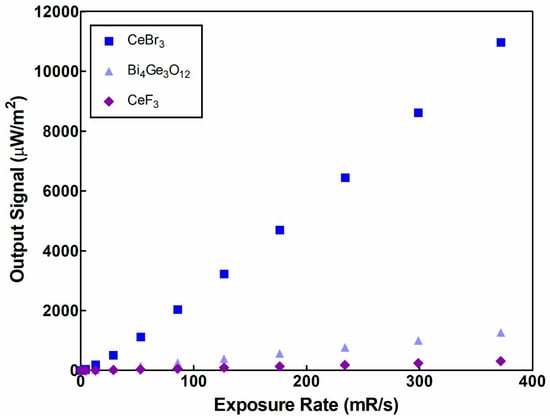
Figure 1.
CeF3’s output signal compared to CeBr3 and BGO.
Figure 2 shows the experimental results regarding the absolute luminescence efficiency of CeF3 compared to the CeBr3 and Bi4Ge3O12 crystals. The results are shown for the available kVp of the X-ray tube, with steps of 10 kVp. A common finding, for the three examined crystals, is that in the examined X-ray range, the luminescence efficiency increases when the tube voltage increases. The increase in the luminescence efficiency is more evident in the range 50–80 kVp, due to the fact that the K-edges of all three materials are in this energy range. CeF3 reaches a maximum value of only 0.8334 EU (EU is the S.I. equivalent μWm−2/(mGy/s) at 140 kVp), whereas the corresponding values for CeBr3 and BGO are 29.49 and 3.41, respectively, despite the higher density (6.16 compared to 5.1 g/cm3) of CeF3 compared with CeBr3 (Table 1) [1]. Luminescence efficiency measurements in higher available X-ray energies could reveal a more efficient performance that possibly fulfils the requirements for nuclear medicine applications.
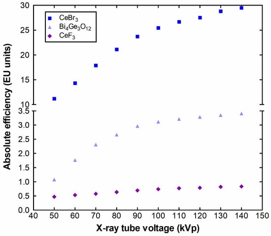
Figure 2.
CeF3′s absolute luminescence efficiency compared to CeBr3 and BGO.
Figure 3 shows the spectral matching values of CeF3 with a broad variety of optical sensors. The emission spectrum of CeF3 in the range of 260–400 nm and with an emission maximum at around 313 nm, which shifted to the shortwave region by 67 nm compared to CeBr3, limits the available sensors commonly used in medical imaging applications that could be coupled with, such as charge coupled devices (CCDs) or complementary metal oxide semiconductors (CMOS) [80].
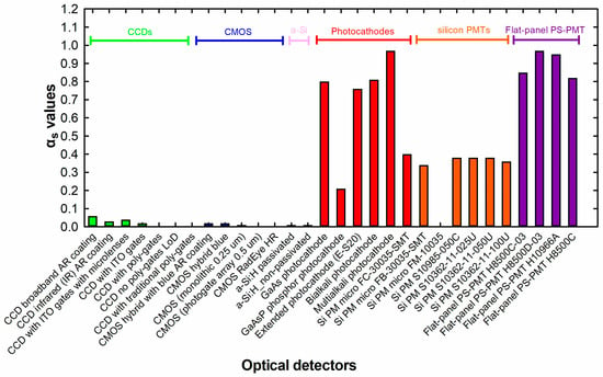
Figure 3.
CeF3 inorganic crystal’s spectral matching factors with a series of digital optical detectors available for medical imaging applications.
The main luminescence mechanism, observed in the CeF3 crystal, is mainly due to 5d-4f transitions of the cerium (Ce3+) ions [25]. Electron transitions from the 4f to the 5d energy level occur when these ions (CeF3) are excited. The return of electrons to the 4f state produces photons. Due to this mechanism, the two primary luminescence bands of the crystal are created. These bands are located at around 290 nm and 340 nm, respectively [25,81,82]. Previous studies have demonstrated an association between the emission at 290 nm and the 5d-4f transitions in cerium (Ce3+) ions. This band is produced by the electrons that radiatively decay from the excited 5d ground state to the 4f ground state [25,81,82]. Frenkel self-trapped excitons are produced as a result of the presence of sub bands in the conduction band, which are obtained from the 5d states of the ions and provide the procedure of the luminescence [25,43,44,45]. The electronic structure and the luminescence mechanism of CeF3 crystal are valuable in evolving scintillators for radiological applications and for other applications in high-energy physics [40,46,47,50,51,52].
As can be depicted from Figure 3, the spectral matching factors between CeF3 and most of the CCDs and CMOS are close to zero. However, CeF3 can be matched with a variety of optical sensors, such as silicon (SiPMs), position-sensitive photomultipliers, etc., which are used in nuclear medicine applications [83,84]. For example, the emission spectrum of CeF3 has a 97% match with the spectral sensitivity of multialkali photocathodes and flat-panel position-sensitive (PS) photomultipliers (H8500D-03) (for both, the spectral matching factor is 0.97). Lower compatibility values can be found with gallium arsenide (GaAs) photocathodes (αs = 0.8) and the extended (E-S20) photocathode used to measure the luminescence efficiency signal in this work (αs = 0.76). This value is also used for the calculation of the AE.
The spectral responses that were used for the calculation of the αs between CeF3 with a series of light sensors are shown in Figure 4 and Figure 5, along with the emitted spectrum of CeF3 [68]. Figure 4 shows the grouped spectral responses of the photocathodes (Figure 4a) and silicon photomultipliers (Figure 4b), whereas Figure 5 shows the grouped spectral responses of the CCDs (Figure 5a) and CMOS (Figure 5b).
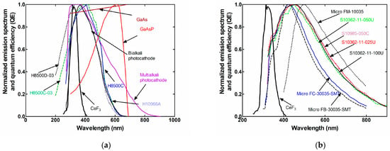
Figure 4.
Spectral responses of (a) photocathodes and (b) silicon PMs, along with the emission spectrum of CeF3.
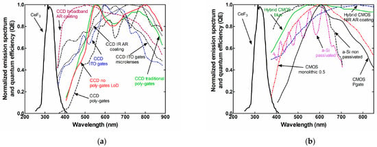
Figure 5.
Spectral responses of (a) CCDs and (b) CMOS, along with the emission spectrum of CeF3.
The CeF3 spectral matching results, presented in the spectral matching factors data of Figure 3, were used to calculate the EE that could be produced upon coupling the specific crystal with the examined optical sensors. Figure 6 and Figure 7 show the calculated effective luminescence efficiency values with the X-ray tube voltage for the above-mentioned optical sensors. Figure 6 shows the grouped spectral responses of the photocathodes (Figure 6a) and silicon photomultipliers (Figure 6b), whereas Figure 7 shows the grouped spectral responses of the CCDs (Figure 7a) and CMOS (Figure 7b).
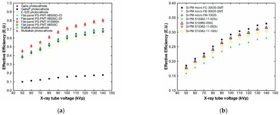
Figure 6.
Effective luminescence efficiency of CeF3 with photocathodes (a) and silicon PMTs (b).
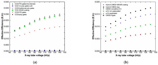
Figure 7.
Effective luminescence efficiency of CeF3 with CCDs (a) and CMOS (b).
Following the spectral matching factor results, the effective efficiency is maximized for multialkali photocathodes and flat-panel position-sensitive photomultipliers, since in these cases, most of the emitted light from the CeF3 scintillator can be adequately collected by the detectors.
The combination of the multialkali photocathode with CeF3 results in the effective efficiency values being reduced by 2.58% compared to the absolute efficiency values at 140 kVp. In the case of the combination of CeF3 with the gallium arsenide photocathode, the corresponding absolute efficiency reduction is 24.26% at 140 kVp.
Typical EE values for single-crystal scintillators, already integrated in medical imaging systems, range from 3 EE for BGO (used, for example, in the GE Discovery IQ scanner, GE Healthcare, Milwaukee, WI, USA) [85], 5 EE for GSO:Ce (Philips Gemini GXL PET/CT, Philips Medical Systems, Eindhoven, The Netherlands) [86], 8 for LYSO:Ce (Philips Gemini TF PET/CT, Philips Medical Systems, Eindhoven, The Netherlands) [87] to 12 for LSO:Ce (Siemens Biograph TruePoint PET/CT, Siemens Healthineers, Forchheim, Germany) [88,89].
Figure 8 shows the X-ray luminescence efficiency of the CeF3 crystal compared to the data for CeBr3 and BGO, in the examined X-ray tube voltage range. The XLE is an important parameter for detectors that are operated as energy integrators. This type of sensor is used in medical imaging systems, in which the signal output is related to the amount of energy that is captured by the crystal. The CeF3 XLE values are below the corresponding ones for CeBr3 and BGO as was expected from the previous findings (Figure 1 and Figure 2). They start from 3.2 × 10⁻⁴ at 50 kVp and drop down to 2.3 × 10⁻⁴ at 140 kVp. The corresponding values for CeBr3 and BGO were 7.6 × 10⁻³ and 7.3 × 10⁻⁴ at 50 kVp, reaching a maximum of 8.9 × 10⁻³ (CeBr3 at 90 kVp) and 1.1 × 10⁻³ (BGO at 80 kVp) and afterwards, both drop down to 8.2 × 10⁻³ and 9.4 × 10⁻⁴ at 140 kVp, respectively. In the case of CeF3, even the characteristic K-edge (at ~40 keV as shown in Figure 9) does not contribute to an XLE increase, like in the case of CeBr3, with a K-edge at almost the same energy with CeF3 (~40 keV) or BGO (~90.5 keV).
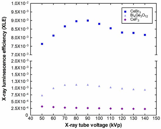
Figure 8.
XLE of CeF3 compared to CeBr3 and BGO.
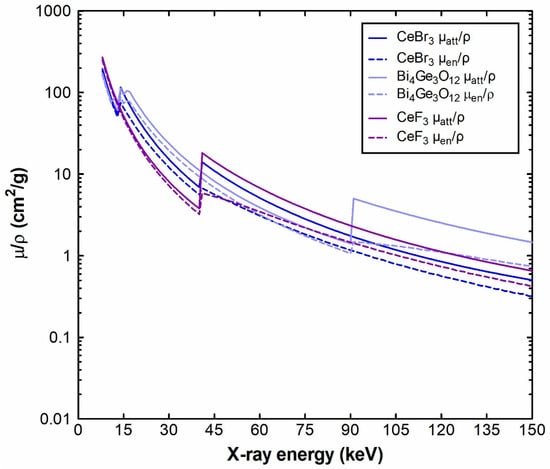
Figure 9.
Mass attenuation coefficients of CeF3 compared to CeBr3 and BGO.
Figure 9 shows the calculated attenuation coefficients (μatt) and the energy absorption (μen) coefficients of CeF3, CeBr3 and BGO, in the energy range 8 to 150 keV. The elemental coefficients (cerium, fluorine, bromine, bismuth (Bi), germanium (Ge) and oxygen (O)) that were used to calculate the CeF3, CeBr3 and BGO mixtures were obtained from the NIST XmuDat database [90,91]. The decrease in the coefficients, except from the sudden increase due to the characteristic K-absorption, for every mixture point, where the probability of photoelectric interaction maximizes, can also be seen in Figure 9.
Figure 10 shows the EAE values of CeF3 compared to CeBr3 and BGO. The energy absorption efficiency strongly depends on the μen and μatt coefficients, shown in Figure 9, as well as on their ratio (μen/μatt, Equation (4)), shown as an inset in Figure 10. Initially, for energies up to 39 keV, CeF3 maintained a higher attenuation coefficient ratio than both CeBr3 and BGO, leading to a higher energy absorption efficiency value at 40 kVp. However, when the energy increases, the energy absorption of BGO showed superior energy absorption efficiency values across the examined energy range, due to the combined effects of the density, higher μen/μatt ratio (from 39 to 90 keV) and the increase in absorption due to the K-edge. Both CeBr3 and CeF3 have close attenuation coefficient values due to the presence of cerium (gram atomic mass = 140.116 g/mol) in both crystals; however, the influence of the three atoms of bromine (gram atomic mass = 79.904 g/mol) is stronger than the corresponding three atoms of fluorine (gram atomic mass = 18.998 g/mol), leading to a gram molecular mass for CeF3 equal to 197.111 g/mol compared to 172.549 g/mol for CeBr3. After the K-edge absorption, CeF3 exhibits a lower μen/μatt ratio and consequently lower EAE values up to 129 keV across the examined energy range.
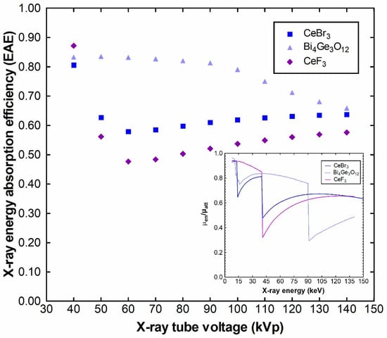
Figure 10.
Energy absorption efficiency and μen/μatt ratios of CeF3 compared to CeBr3 and BGO.
3. Materials and Methods
The cubic-shaped (edge of 10 mm) and polished CeF3 crystal was obtained from Advatech (London, UK) [68]. For the irradiation of the sample, a typical radiological X-ray tube (CPI Inc., Georgetown, ON, Canada, model CMP 200 DR high-frequency X-ray generator and an X-ray tube (IAE SpA, Milano, Italy, model SpA-RTM90HS) was used, with voltage settings of 50–140 kVp, tube current fixed at 63 mAs, large focus (1.2 mm), a source to detector distance of 72.5 cm and an additional aluminum (Al) filter with a thickness of 20 mm.
The emitted light energy produced by the crystals per unit area was determined as the output signal in the energy range that diagnostic medical X-ray tubes allow (50–140 kVp). The methodology is described in detail in [1].
The CeF3 sample was wrapped with Teflon tape (only one face was free) and inserted in the input port of an integrating sphere ((Newport Corp., Irvine, CA, USA, Oriel model 70451). The light that was produced by the sample, after X-ray excitation, was collected by a photomultiplier tube (PMT, (EMI, London, UK, EMI model 9798). The PMT’s photocathode was the extended sensitivity (S20) type. The dose was monitored using an RTI Piranha P100B dosimeter (Mölndal, Sweden). In our experiments, the PMT works with a 22 volts difference between the initial dynode (all dynodes shorted) and the photocathode. The produced current is recorded by a sub-femtoamp remote source meter (Keithley, Cleveland, OH, USA, model 6430).
The ratio of the light energy flux emitted by the examined sample, normalized by the X-ray exposure rate, can be expressed as the absolute luminescence efficiency:
In Equation (1), is the light energy flux (output signal) in units of μW m−2. is the exposure rate (mR s−1). ielec is the current produced by the electrometer in pA and S denotes the surface of the crystal, excited by X-rays (mm2). The peak sensitivity of the photocathode (ηp) is expressed in units of pA/W. is the spectral matching between the light source (in this case, crystal) to the spectral response of the optical sensor (in this case, the photocathode). Finally, the percentage of the sample’s emitted light escaping the integrating sphere and reacting with the PMT is the geometric light collection efficiency () with a measured value of 15.6. The units of the luminescence efficiency are EU = (μW m−2)/(mR s−1). The experimental error is within ±3.4% due to the combined effects of the reproducibility of the X-ray tube output and optical measurement setups.
If the AE is reduced by the spectral matching factor () (denoting the percent of the light produced by the scintillator, which is within the same wavelength range as the optical response of a light sensor), then the effective efficiency is derived [1]:
The effective efficiency was calculated for various optical detectors, often used in medical applications, while the spectrum of CeF3 was obtained from manufacturer data [68].
The X-ray luminescence efficiency (XLE) is the ratio of the crystal’s emitted light energy flux over the X-ray energy flux () [1].
Calculation of the XLE can be performed by the conversion of the X-ray exposure (in Equation (1)) to the X-ray energy flux ), using where is the X-ray energy flux per exposure rate:
is the X-ray mass energy absorption coefficient of the air and is the average energy/unit of charge, for the production of an electron/ion pair in the air.
The energy absorption efficiency is used to account for the energy locally absorbed at the points of X-ray interaction, within the crystal [1]:
In Equation (4), the X-ray photon fluence is depicted by Φ0(E) in units of photons/unit of area and is multiplied by the energy of the photons (E), in order to reproduce the X-ray energy fluence. The X-ray mass attenuation (μatt(E)/ρ) and the energy absorption coefficients (μen(E)/ρ) were calculated from the NIST XmuDat database [90,91]. The crystal thickness is denoted by W and the density by , in units of g/cm3 [92].
4. Conclusions
This study aimed to investigate the luminescence properties of a CeF3 single-crystal inorganic scintillator as a possible alternative to high-luminous but hygroscopic CeBr3. The experiments were performed under the exposure of a typical X-ray unit, with X-rays spanning from 50 to 140 kVp. The fluorine in CeF3 appeared to drastically reduce the luminescence efficiency, compared to the CeBr3 crystal and other commercially used crystals in medical applications such as BGO. Furthermore, the emission maximum moved even lower than CeBr3, towards the lower part of the visible spectrum and beyond, making CeF3 suitable for spectral coupling with some multialkali photocathodes and flat-panel position-sensitive photomultipliers applied in nuclear medicine detectors, but completely unsuitable for spectral matching with CCDs and CMOS, used in a variety of medical imaging sensors. The obtained luminescence efficiency results denote that CeF3 cannot be applied in medical imaging applications, covering the range 50–140 kVp; however, examination of its luminescence efficiency at higher energies could reveal a possible applicability for nuclear medicine detectors.
Author Contributions
Conceptualization, C.M. and V.N.; methodology, C.M., V.N., I.V., N.K., G.F. and I.K.; software, V.N.; validation, N.K. and I.K.; formal analysis, C.M., N.K. and V.N.; investigation, C.M., N.K., G.F., V.N., A.B. and I.V.; resources, A.B.; data curation, C.M., N.K., V.N., G.F. and I.K.; writing—original draft preparation, V.N. and C.M.; writing—review and editing, C.M., I.K., N.K., A.B. and I.V.; visualization, I.V.; supervision, C.M.; project administration, C.M. and I.V. All authors have read and agreed to the published version of the manuscript.
Funding
This research received no external funding.
Data Availability Statement
Data are contained within the article.
Conflicts of Interest
The authors declare no conflicts of interest.
References
- Linardatos, D.; Michail, C.; Kalyvas, N.; Ninos, K.; Bakas, A.; Valais, I.; Fountos, G.; Kandarakis, I. Luminescence Efficiency of Cerium Bromide Single Crystal under X-ray Radiation. Crystals 2022, 12, 909. [Google Scholar] [CrossRef]
- Zou, Z.; Weng, J.; Liu, C.; Lin, Y.; Zhu, J.; Sun, Y.; Huang, J.; Gong, G.; Wen, H. Crystal Growth, Photoluminescence and Radioluminescence Properties of Ce3+-Doped Ba3Y(PO4)3 Crystal. Crystals 2024, 14, 431. [Google Scholar] [CrossRef]
- Ciomaga Hatnean, V.C.; Pui, A.; Simonov, A.; Ciomaga Hatnean, M. Crystal Growth of the R2SiO5 Compounds (R = Dy, Ho, and Er) by the Floating Zone Method Using a Laser-Diode-Heated Furnace. Crystals 2023, 13, 1687. [Google Scholar] [CrossRef]
- Sahani, R.M.; Pandya, A. Novel Epoxy-bPBD-BisMSB Composite Plastic Scintillator for Alpha, Beta and Gamma Radiation Detection. Sci. Rep. 2024, 14, 6531. [Google Scholar] [CrossRef] [PubMed]
- Pagano, F.; Král, J.; Děcká, K.; Pizzichemi, M.; Mihóková, E.; Čuba, V.; Auffray, E. Nanocrystalline Lead Halide Perovskites to Boost Time-of-Flight Performance of Medical Imaging Detectors. Adv. Mater. Interfaces 2024, 11, 2300659. [Google Scholar] [CrossRef]
- Lai, Z.; Wang, W.; Liu, F.; Liu, Z.; Wang, S.; Lai, J.; Chen, J.; Zhang, H.; Xu, R.; Wang, L. High-Quality CsI(Tl) Single-Crystal Flake Scintillators Grown by the Space-Confined Solution Method. Opt. Mater. 2024, 151, 115333. [Google Scholar] [CrossRef]
- Mahato, S.; Makowski, M.; Bose, S.; Kowal, D.; Kuddus Sheikh, M.A.; Braueninger-Wemer, P.; Witkowski, M.E.; Ray, S.K.; Drozdowski, W.; Birowosuto, M.D. Improvement of Light Output of MAPbBr3 Single Crystal for Ultrafast and Bright Cryogenic Scintillator. J. Phys. Chem. Lett. 2024, 15, 3713–3720. [Google Scholar] [CrossRef]
- Glodo, J.; van Loef, E.; Wang, Y.; Bhattacharya, P.; Pandian, L.S.; Shirwadkar, U.; Hubble, I.; Schott, J.; Muller, M. Novel High-Stopping Power Scintillators for Medical Applications. In Proceedings of the Medical Imaging 2024: Physics of Medical Imaging, SPIE, San Diego, CA, USA, 1 April 2024; Volume 12925, pp. 585–595. [Google Scholar]
- Nazarov, M.; Tsukerblat, B. Optical Lines in Europium and Terbium-Activated Yttrium Tantalate Phosphor: Combined Experimental and Group-Theoretical Analysis. Optics 2023, 4, 510–524. [Google Scholar] [CrossRef]
- Komendo, I.; Mechinsky, V.; Fedorov, A.; Dosovitskiy, G.; Schukin, V.; Kuznetsova, D.; Zykova, M.; Velikodny, Y.; Korjik, M. Effect of the Synthesis Conditions on the Morphology, Luminescence and Scintillation Properties of a New Light Scintillation Material Li2CaSiO4:Eu2+ for Neutron and Charged Particle Detection. Inorganics 2022, 10, 127. [Google Scholar] [CrossRef]
- Cheng, Y.; Huang, Y.; Yu, G. N-S-Co-Doped Carbon Dot Blue Fluorescence Preparation and Baicalein Detection. Inorganics 2024, 12, 154. [Google Scholar] [CrossRef]
- Higgins, W.M.; Churilov, A.; van Loef, E.; Glodo, J.; Squillante, M.; Shah, K. Crystal Growth of Large Diameter LaBr3:Ce and CeBr3. J. Cryst. Growth 2008, 310, 2085–2089. [Google Scholar] [CrossRef]
- Wei, H.; Martin, V.; Lindsey, A.; Zhuravleva, M.; Melcher, C.L. The Scintillation Properties of CeBr3−xClx Single Crystals. J. Lumin. 2014, 156, 175–179. [Google Scholar] [CrossRef]
- Loyd, M.; Stand, L.; Rutstrom, D.; Wu, Y.; Glodo, J.; Shah, K.; Koschan, M.; Melcher, C.L.; Zhuravleva, M. Investigation of CeBr3−xIx Scintillators. J. Cryst. Growth 2020, 531, 125365. [Google Scholar] [CrossRef]
- Kandarakis, I. Luminescence in Medical Image Science. J. Lumin. 2016, 169, 553–558. [Google Scholar] [CrossRef]
- Madej, A.; Witkowski, M.E.; Wojtowicz, A.J.; Zych, E. Photo- and Radioluminescent Properties of Undoped and Bi-Doped Lu2WO6 Powders at 10–300K. J. Lumin. 2015, 160, 50–56. [Google Scholar] [CrossRef]
- Xie, S.; Zhang, X.; Zhang, Y.; Ying, G.; Huang, Q.; Xu, J.; Peng, Q. Evaluation of Various Scintillator Materials in Radiation Detector Design for Positron Emission Tomography (PET). Crystals 2020, 10, 869. [Google Scholar] [CrossRef]
- Koppert, W.J.C.; Dietze, M.M.A.; Velden, S.; Steenbergen, J.H.L.; Jong, H.W.A.M. A Comparative Study of NaI(Tl), CeBr3 and CZT for Use in a Real-Time Simultaneous Nuclear and Fluoroscopic Dual-Layer Detector. Phys. Med. Biol. 2019, 64, 135012. [Google Scholar] [CrossRef] [PubMed]
- Lecoq, P. Development of New Scintillators for Medical Applications. Nucl. Instrum. Methods Phys. Res. Sect. Accel. Spectrom. Detect. Assoc. Equip. 2016, 809, 130–139. [Google Scholar] [CrossRef]
- Kim, K.J.; Furuya, Y.; Kamada, K.; Murakami, R.; Kochurikhin, V.V.; Yoshino, M.; Chiba, H.; Kurosawa, S.; Yamaji, A.; Shoji, Y.; et al. Growth and Scintillation Properties of Directionally Solidified Ce:LaBr3/AEBr2 (AE = Mg, Ca, Sr, Ba) Eutectic System. Crystals 2020, 10, 584. [Google Scholar] [CrossRef]
- Carone, D.; Klepov, V.V.; Misture, S.T.; Schaeperkoetter, J.C.; Jacobsohn, L.G.; Aziziha, M.; Schorne-Pinto, J.; Thomson, S.A.J.; Hines, A.T.; Besmann, T.M.; et al. Luminescence and Scintillation in the Niobium Doped Oxyfluoride Rb4Ge5O9F6:Nb. Inorganics 2022, 10, 83. [Google Scholar] [CrossRef]
- Linardatos, D.; Ntoupis, V.; Tseremoglou, S.; Valais, I.; Ninos, K.; Bakas, A.; Lavdas, E.; Kandarakis, I.; Kalyvas, N.; Fountos, G.; et al. Light Output Dependence of CeBr3 Hygroscopic Scintillator upon Temperature. Procedia Struct. Integr. 2023, 47, 80–86. [Google Scholar] [CrossRef]
- Li, P.; Gridin, S.; Ucer, K.B.; Williams, R.T.; Menge, P.R. Picosecond Absorption Spectroscopy of Self-Trapped Excitons and Ce Excited States in CeBr3 and La1−xCexBr3. Phys. Rev. B 2019, 99, 104301. [Google Scholar] [CrossRef]
- Lecoq, P.; Gektin, A.; Korzhik, M. Scintillation and Inorganic Scintillators. In Inorganic Scintillators for Detector Systems: Physical Principles and Crystal Engineering; Lecoq, P., Gektin, A., Korzhik, M., Eds.; Springer International Publishing: Cham, Switzerland, 2017; pp. 1–41. ISBN 978-3-319-45522-8. [Google Scholar]
- Kochan, O.; Chornodolskyy, Y.; Selech, J.; Karnaushenko, V.; Przystupa, К.; Kotlov, A.; Demkiv, T.; Vistovskyy, V.; Stryhanyuk, H.; Rodnyi, P.; et al. Energy Structure and Luminescence of CeF3 Crystals. Materials 2021, 14, 4243. [Google Scholar] [CrossRef]
- Przystupa, K.; Chornodolskyy, Y.M.; Selech, J.; Karnaushenko, V.O.; Demkiv, T.M.; Kochan, O.; Syrotyuk, S.V.; Voloshinovskii, A.S. The Influence of Halide Ion Substitution on Energy Structure and Luminescence Efficiency in CeBr2I and CeBrI2 Crystals. Materials 2023, 16, 5085. [Google Scholar] [CrossRef]
- Chornodolskyy, Y.M.; Karnaushenko, V.O.; Vistovskyy, V.V.; Syrotyuk, S.V.; Gektin, A.V.; Voloshinovskii, A.S. Energy Band Structure Peculiarities and Luminescent Parameters of CeX3 (X = Cl, Br, I) Crystals. J. Lumin. 2021, 237, 118147. [Google Scholar] [CrossRef]
- Russell-Webster, B.; Abboud, K.A.; Christou, G. Molecular Nanoparticles of Cerium Dioxide: Structure-Directing Effect of Halide Ions. Chem. Commun. 2020, 56, 5382–5385. [Google Scholar] [CrossRef]
- Chipaux, R.; Faure, J.-L.; Rebourgeard, P.; Dauphin, G.; Safieh, J. Behaviour of CeF3 Scintillator in an LHC-like Environment. Nucl. Instrum. Methods Phys. Res. Sect. Accel. Spectrom. Detect. Assoc. Equip. 1994, 345, 440–444. [Google Scholar] [CrossRef]
- Schneegans, M.A. Cerium Fluoride Crystals for Calorimetry at LHC. Nucl. Instrum. Methods Phys. Res. Sect. Accel. Spectrom. Detect. Assoc. Equip. 1994, 344, 47–56. [Google Scholar] [CrossRef]
- Ferrere, D.; Lebeau, M.; Schneegans, M.; Vivargent, M.; Lecoq, P. High Resolution Crystal Calorimetry at LHC. Nucl. Instrum. Methods Phys. Res. Sect. Accel. Spectrom. Detect. Assoc. Equip. 1992, 315, 332–336. [Google Scholar] [CrossRef][Green Version]
- Auffray, E.; Beckers, T.; Bourotte, J.; Chipaux, R.; Commichau, V.; Dafinei, I.; Depasse, P.; Djambazov, L.; Dydak, U.; El Mamouni, H.; et al. Performance of a Cerium Fluoride Crystal Matrix Measured in High-Energy Particle Beams. Nucl. Instrum. Methods Phys. Res. Sect. Accel. Spectrom. Detect. Assoc. Equip. 1996, 378, 171–178. [Google Scholar] [CrossRef]
- Nikl, M.; Mares, J.A.; Dusek, M.; Lecoq, P.; Dafinei, I.; Auffray, E.; Pazzi, G.P.; Fabeni, P.; Jindra, J.; Skoda, Z. Decay Kinetics of Ce3+ Ions under Gamma and KrF Excimer Laser Excitation in CeF3 Single Crystals. J. Phys. Condens. Matter 1995, 7, 6355. [Google Scholar] [CrossRef]
- Auffray, E.; Beckers, T.; Chipaux, R.; Dafinei, I.; Depasse, P.; El Mamouni, H.; Faure, J.L.; Fay, J.; Hillemanns, H.; Ille, B.; et al. First Results on Large Cerium Fluoride Crystals in A Test Beam. MRS Online Proc. Libr. 1994, 348, 117–122. [Google Scholar] [CrossRef]
- Pedrini, C.; Moine, B.; Bouttet, D.; Belsky, A.N.; Mikhailin, V.V.; Vasil’ev, A.N.; Zinin, E.I. Time-Resolved Luminescence of CeF3 Crystals Excited by X-ray Synchrotron Radiation. Chem. Phys. Lett. 1993, 206, 470–474. [Google Scholar] [CrossRef]
- Auffray, E.; Baccaro, S.; Beckers, T.; Benhammou, Y.; Belsky, A.N.; Borgia, B.; Boutet, D.; Chipaux, R.; Dafinei, I.; de Notaristefani, F.; et al. Extensive Studies on CeF3 Crystals, a Good Candidate for Electromagnetic Calorimetry at Future Accelerators. Nucl. Instrum. Methods Phys. Res. Sect. Accel. Spectrom. Detect. Assoc. Equip. 1996, 383, 367–390. [Google Scholar] [CrossRef][Green Version]
- Inagaki, T.; Yoshimura, Y.; Kanda, Y.; Matsumoto, Y.; Minami, K. Development of CeF3 Crystal for High-Energy Electromagnetic Calorimetry. Nucl. Instrum. Methods Phys. Res. Sect. Accel. Spectrom. Detect. Assoc. Equip. 2000, 443, 126–135. [Google Scholar] [CrossRef]
- Bianchini, L.; Dissertori, G.; Donegà, M.; Lustermann, W.; Marini, A.; Micheli, F.; Nessi-Tedaldi, F.; Pandolfi, F.; Peruzzi, M.; Schonenberger, M.; et al. High-Energy Electron Test Results of a Calorimeter Prototype Based on CeF3 for HL-LHC Applications. In Proceedings of the 2015 IEEE Nuclear Science Symposium and Medical Imaging Conference (NSS/MIC), San Diego, CA, USA, 31 October–7 November 2015; pp. 1–2. [Google Scholar]
- Karimov, D.N.; Lisovenko, D.S.; Ivanova, A.G.; Grebenev, V.V.; Popov, P.A.; Sizova, N.L. Bridgman Growth and Physical Properties Anisotropy of CeF3 Single Crystals. Crystals 2021, 11, 793. [Google Scholar] [CrossRef]
- Víllora, E.G.; Yuan, D.; Shimamura, K. CeF3 Single Crystals for UV-VIS-IR Optical Isolators. Int. J. Appl. Ceram. Technol. 2023, 20, 2047–2054. [Google Scholar] [CrossRef]
- Yang, W.; Kong, X.; Fu, B.; Yang, Y.; Chen, R.; Zuo, C.; Liu, H.; Yu, Y.; Zeng, F.; Li, C. Optical Properties of CeF3 Crystal at High Temperature or Pressure by First Principles and Its Application in Isolators. Opt. Mater. 2024, 154, 115758. [Google Scholar] [CrossRef]
- Yuan, D.; Víllora, E.G.; Shimamura, K. Regular Hexagonal-Prism Microvoids in CeF3 Single Crystals. J. Cryst. Growth 2021, 558, 126024. [Google Scholar] [CrossRef]
- Chylii, M.; Loghina, L.; Kaderavkova, A.; Slang, S.; Rodriguez-Pereira, J.; Frumarova, B.; Vlcek, M. Morphology and Optical Properties of CeF3 and CeF3:Tb Nanocrystals: The Dominant Role of the Reaction Thermal Mode. Mater. Chem. Phys. 2021, 260, 124161. [Google Scholar] [CrossRef]
- Zhu, L.; Li, Q.; Liu, X.; Li, J.; Zhang, Y.; Meng, J.; Cao, X. Morphological Control and Luminescent Properties of CeF3 Nanocrystals. J. Phys. Chem. C 2007, 111, 5898–5903. [Google Scholar] [CrossRef]
- Sizova, N.L.; Karimov, D.N.; Kosova, T.B.; Lisovenko, D.S. Mechanical Properties of CeF3 Single Crystals. Crystallogr. Rep. 2019, 64, 942–946. [Google Scholar] [CrossRef]
- Li, H.; Wang, J.; Chen, J.; Dai, Y.; Su, L.; Li, X.; Kalashnikova, A.M.; Wu, A. Bridgman Growth and Magneto-Optical Properties of CeF3 Crystal as Faraday Rotator. Opt. Mater. 2020, 100, 109675. [Google Scholar] [CrossRef]
- Kamenskikh, I.; Tishchenko, E.; Kirm, M.; Omelkov, S.; Belsky, A.; Vasil’ev, A. Decay Kinetics of CeF3 under VUV and X-ray Synchrotron Radiation. Symmetry 2020, 12, 914. [Google Scholar] [CrossRef]
- Klamra, W.; Sibczynski, P.; Moszynski, M.; Czarnacki, W.; Kozlov, V. Extensive Studies on Light Yield Non-Proportional Response of Undoped CeF3 at Room and Liquid Nitrogen Temperatures. J. Instrum. 2013, 8, P06003. [Google Scholar] [CrossRef]
- Thongpool, V.; Phunpueok, A.; Jaiyen, S.; Choosakul, N.; Aphairaj, D.; Thongchai, P.; Singhaseree, C. Preparation of CeF3 Nanoparticles Loaded PPO/PVT Composites for Radiation Detection. Dig. J. Nanomater. Biostructures 2022, 16, 621–625. [Google Scholar] [CrossRef]
- Lacy, J.H.; Patenotte, G.E.; Kinney, A.C.; Majumder, P.K. Broadband High-Precision Faraday Rotation Spectroscopy with Uniaxial Single Crystal CeF3 Modulator. Photonics 2024, 11, 304. [Google Scholar] [CrossRef]
- Starobor, A.; Mironov, E.; Palashov, O. High-Power Faraday Isolator on a Uniaxial CeF3 Crystal. Opt. Lett. 2019, 44, 1297–1299. [Google Scholar] [CrossRef]
- Vojna, D.; Slezák, O.; Yasuhara, R.; Furuse, H.; Lucianetti, A.; Mocek, T. Faraday Rotation of Dy2O3, CeF3 and Y3Fe5O12 at the Mid-Infrared Wavelengths. Materials 2020, 13, 5324. [Google Scholar] [CrossRef]
- Lecoq, P. How High Energy Physics Is Driving the Development of New Scintillators. In Proceedings of the Fifth International Conference on Inorganic Scintillators and Their Applications, Moscow, Russia, 16–20 August 1999; CERN: Moscow, Russia, 1999. [Google Scholar]
- Grynyov, B.; Ryzhikov, V.; Kim, J.K.; Jae, M. Scintillator Crystals, Radiation Detectors & Instruments on Their Base; V. Ryzhikov: Kharkiv, Ukraine, 2004; ISBN 966-02-3314-0. [Google Scholar]
- Michail, C.; Liaparinos, P.; Kalyvas, N.; Kandarakis, I.; Fountos, G.; Valais, I. Phosphors and Scintillators in Biomedical Imaging. Crystals 2024, 14, 169. [Google Scholar] [CrossRef]
- Valais, I.; Michail, C.; David, S.; Nomicos, C.D.; Panayiotakis, G.S.; Kandarakis, I. A Comparative Study of the Luminescence Properties of LYSO:Ce, LSO:Ce, GSO:Ce and BGO Single Crystal Scintillators for Use in Medical X-ray Imaging. Phys. Med. 2008, 24, 122–125. [Google Scholar] [CrossRef] [PubMed]
- van Eijk, C.W.E. Inorganic Scintillators in Medical Imaging. Phys. Med. Biol. 2002, 47, R85–R106. [Google Scholar] [CrossRef]
- Balcerzyk, M.; Moszynski, M.; Kapusta, M.; Wolski, D.; Pawelke, J.; Melcher, C.L. YSO, LSO, GSO and LGSO. A Study of Energy Resolution and Nonproportionality. IEEE Trans. Nucl. Sci. 2000, 47, 1319–1323. [Google Scholar] [CrossRef]
- Kozma, P.; Kozma, P. Radiation Sensitivity of GSO and LSO Scintillation Detectors. Nucl. Instrum. Methods Phys. Res. Sect. Accel. Spectrom. Detect. Assoc. Equip. 2005, 539, 132–136. [Google Scholar] [CrossRef]
- Holl, I.; Lorenz, E.; Mageras, G. A Measurement of the Light Yield of Common Inorganic Scintillators. IEEE Trans. Nucl. Sci. 1988, 35, 105–109. [Google Scholar] [CrossRef]
- Passeri, A.; Formiconi, A.R. SPECT and Planar Imaging in Nuclear Medicine. In Ionizing Radiation Detectors for Medical Imaging; World Scientific: Singapore, 2004; pp. 235–285. ISBN 978-981-238-674-8. [Google Scholar]
- Christian, J. Advances in CMOS SSPM Detectors. In Biological and Medical Sensor Technologies; Iniewski, K., Ed.; CRC Press: Boca Raton, FL, USA, 2017; p. 327. ISBN 978-1-138-07321-0. [Google Scholar]
- Stolberg-Rohr, T.; Hawkins, G.J. Spectral Design of Temperature-Invariant Narrow Bandpass Filters for the Mid-Infrared. Opt. Express 2015, 23, 580. [Google Scholar] [CrossRef]
- Rodnyj, P.A. Interaction of Ionizing Radiation with Scintillators. In Physical Processes in Inorganic Scintillators; The CRC Press Laser and Optical Science and Technology Series; CRC Press: Boca Raton, FL, USA, 1997; p. 17. ISBN 978-0-8493-3788-8. [Google Scholar]
- Kawaguchi, N.; Kimura, H.; Nakauchi, D.; Kato, T.; Yanagida, T. Inorganic Fluoride Scintillators. In Phosphors for Radiation Detectors; John Wiley & Sons, Ltd.: Hoboken, NJ, USA, 2022; pp. 91–120. ISBN 978-1-119-58336-3. [Google Scholar]
- van Loef, E.V.; Shah, K.S. Advances in Scintillators for Medical Imaging Applications. In Proceedings of the SPIE, San Diego, CA, USA, 12 September 2014; Barber, H.B., Furenlid, L.R., Roehrig, H.N., Eds.; p. 92140A. [Google Scholar]
- Drozdowski, W.; Dorenbos, P.; Bos, A.J.J.; Owens, A.; Richaud, D. Gamma Radiation Hardness of Ø1″ × 1″ LaBr3:Ce, LaCl3:Ce, and CeBr3 Scintillators. In Proceedings of the 2008 IEEE Nuclear Science Symposium Conference Record, Dresden, Germany, 19–25 October 2008; pp. 2856–2858. [Google Scholar]
- CeF3—Cerium Fluoride Scintillator Crystal|Advatech UK. Available online: https://www.advatech-uk.co.uk/cef3.html (accessed on 2 May 2024).
- CeBr3—Cerium Bromide Scintillator Crystal|Advatech UK. Available online: https://www.advatech-uk.co.uk/cebr3.html (accessed on 2 May 2024).
- Shen, H.; Xu, J.Y.; Ping, W.J.; He, Q.B.; Zhang, Y.; Jin, M.; Jiang, G.J. Growth, Mechanical and Thermal Properties of Bi4Si3O12 Single Crystals. Chin. Phys. Lett. 2012, 29, 076501. [Google Scholar] [CrossRef]
- Cerium Fluoride Crystal CeF3 Scintillation Crystal–MSE Supplies LLC. Available online: https://www.msesupplies.com/products/cerium-fluoride-cef3-crystal?variant=40204171444282 (accessed on 7 June 2024).
- Li, H.; Ge, W.; Li, J.; Dai, Y.; Chen, J.; Su, L.; Jin, Z.; Ma, G.; Li, X.; Wu, A. Temperature-Dependent Terahertz Dielectric Modulation of a High-Performance Magneto-Optic CeF3 Crystal. Phys. B Condens. Matter 2020, 599, 412468. [Google Scholar] [CrossRef]
- Kobayashi, M.; Ishii, M.; Krivandina, E.A.; Litvinov, M.M.; Peresypkin, A.I.; Prokoshkin, Y.D.; Rykalin, V.I.; Sobolev, B.P.; Takamatsu, K.; Vasil’chenko, V.G. Cerium Fluoride, a Highly Radiation-Resistive Scintillator. Nucl. Instrum. Methods Phys. Res. Sect. Accel. Spectrom. Detect. Assoc. Equip. 1991, 302, 443–446. [Google Scholar] [CrossRef]
- Kozma, P.; Kozma, P. Radiation Resistivity of BGO Crystals Due to Low-Energy Gamma-Rays. Nucl. Instrum. Methods Phys. Res. Sect. Accel. Spectrom. Detect. Assoc. Equip. 2003, 501, 499–504. [Google Scholar] [CrossRef]
- Snigireva, O.A.; Solomonov, V.I. Role of the Ce2+ Ions in Cerium Fluoride Luminescence. Phys. Solid State 2005, 47, 1443–1445. [Google Scholar] [CrossRef]
- Yang, F.; Mao, R.; Zhang, L.; Zhu, R.-Y. A Study on Radiation Damage in BGO and PWO-II Crystals. J. Phys. Conf. Ser. 2012, 404, 012025. [Google Scholar] [CrossRef]
- Sasano, M.; Nishioka, H.; Okuyama, S.; Nakazawa, K.; Makishima, K.; Yamada, S.; Yuasa, T.; Okumura, A.; Kataoka, J.; Fukazawa, Y.; et al. Geometry Dependence of the Light Collection Efficiency of BGO Crystal Scintillators Read out by Avalanche Photo Diodes. Nucl. Instrum. Methods Phys. Res. Sect. Accel. Spectrom. Detect. Assoc. Equip. 2013, 715, 105–111. [Google Scholar] [CrossRef]
- Chaiphaksa, W.; Limkitjaroenporn, P.; Kim, H.J.; Kaewkhao, J. Moh’s Hardness Scale and Micro Vicker’s Hardness Study of Bgo and Lyso Inorganic Scintillators. J. Phys. Conf. Ser. 2018, 970, 012005. [Google Scholar] [CrossRef]
- Kozma, P.; Bajgar, R.; Kozma, P. Radiation Resistivity of PbF2 Crystals. Nucl. Instrum. Methods Phys. Res. Sect. Accel. Spectrom. Detect. Assoc. Equip. 2002, 484, 149–152. [Google Scholar] [CrossRef]
- Magnan, P. Detection of Visible Photons in CCD and CMOS: A Comparative View. Nucl. Instrum. Methods Phys. Res. Sect. Accel. Spectrom. Detect. Assoc. Equip. 2003, 504, 199–212. [Google Scholar] [CrossRef]
- Yang, Y.; Zhang, L.; Quan, C.; Li, S.; Zhang, S.; Zhang, Y.; Fang, Q.; He, M.; Xu, M.; Hang, Y. Growth, Thermal, and Polarized Spectroscopic Properties of Nd:CeF3 Crystal for Dual-Wavelength Lasers. J. Lumin. 2020, 227, 117558. [Google Scholar] [CrossRef]
- Shimamura, K.; Víllora, E.G.; Nakakita, S.; Nikl, M.; Ichinose, N. Growth and Scintillation Characteristics of CeF3, PrF3 and NdF3 Single Crystals. J. Cryst. Growth 2004, 264, 208–215. [Google Scholar] [CrossRef]
- Schaber, J.; Xiang, R.; Gaponik, N. Review of Photocathodes for Electron Beam Sources in Particle Accelerators. J. Mater. Chem. C 2023, 11, 3162–3179. [Google Scholar] [CrossRef]
- MA, L.; Chen, L.; Huang, G.; Hu, J.; Han, X.; Hua, Z.; Huang, X.; Jin, M.; Jiang, X.; Jin, Z.; et al. The Time Resolution Improvement of Cherenkov-Radiator-Window Photomultiplier Tube. J. Instrum. 2023, 18, C12020. [Google Scholar] [CrossRef]
- Ponti, E.D.; Crivellaro, C.; Morzenti, S.; Monaco, L.; Todde, S.; Landoni, C.; Elisei, F.; Musarra, M.; Guerra, L. Clinical Application of a High Sensitivity BGO PET/CT Scanner: Effects of Acquisition Protocols and Reconstruction Parameters on Lesions Quantification. Curr. Radiopharm. 2022, 15, 218–227. [Google Scholar] [CrossRef] [PubMed]
- Sathiakumar, C.; Som, S.; Eberl, S.; Lin, P. NEMA NU 2-2001 Performance Testing of a Philips Gemini GXL PET/CT Scanner. Australas. Phys. Eng. Sci. Med. 2010, 33, 199–209. [Google Scholar] [CrossRef] [PubMed]
- Surti, S.; Kuhn, A.; Werner, M.E.; Perkins, A.E.; Kolthammer, J.; Karp, J.S. Performance of Philips Gemini TF PET/CT Scanner with Special Consideration for Its Time-of-Flight Imaging Capabilities. J. Nucl. Med. 2007, 48, 471–480. [Google Scholar]
- Jakoby, B.W.; Bercier, Y.; Watson, C.C.; Bendriem, B.; Townsend, D.W. Performance Characteristics of a New LSO PET/CT Scanner with Extended Axial Field-of-View and PSF Reconstruction. IEEE Trans. Nucl. Sci. 2009, 56, 633–639. [Google Scholar] [CrossRef]
- Valais, I.; David, S.; Michail, C.; Konstantinidis, A.; Kandarakis, I.; Panayiotakis, G.S. Investigation of Luminescent Properties of LSO:Ce, LYSO:Ce and GSO:Ce Crystal Scintillators under Low-Energy γ-Ray Excitation Used in Nuclear Imaging. Nucl. Instrum. Methods Phys. Res. Sect. Accel. Spectrom. Detect. Assoc. Equip. 2007, 581, 99–102. [Google Scholar] [CrossRef]
- Storm, L.; Israel, H.I. Photon Cross Sections from 1 keV to 100 MeV for Elements Z = 1 to Z = 100. At. Data Nucl. Data Tables 1970, 7, 565–681. [Google Scholar] [CrossRef]
- Hubbell, J.H.; Seltzer, S.M. Tables of X-ray Mass Attenuation Coefficients and Mass Energy-Absorption Coefficients; NIST Standard Reference Database 126; National Institute of Standards and Technology-PL: Gaithersburg, MD, USA, 1995. [Google Scholar]
- Boone, J. X-ray Production, Interaction, and Detection in Diagnostic Imaging. In Handbook of Medical Imaging. Volume 1: Physics and Psychophysics; Beutel, J., Kundel, H.L., Van Metter, R.L., Eds.; SPIE Press: Bellingham, WA, USA, 2000; Volume 1, pp. 36–57. ISBN 978-0-8194-7772-9. [Google Scholar]
Disclaimer/Publisher’s Note: The statements, opinions and data contained in all publications are solely those of the individual author(s) and contributor(s) and not of MDPI and/or the editor(s). MDPI and/or the editor(s) disclaim responsibility for any injury to people or property resulting from any ideas, methods, instructions or products referred to in the content. |
© 2024 by the authors. Licensee MDPI, Basel, Switzerland. This article is an open access article distributed under the terms and conditions of the Creative Commons Attribution (CC BY) license (https://creativecommons.org/licenses/by/4.0/).