

The Integration of Thermal Energy Storage Within Metal Hydride Systems: A Comprehensive Review

 , ,
, ,  ,
,  and
and
Abstract

1. Introduction
2. Metal Hydrides
2.1. Overview
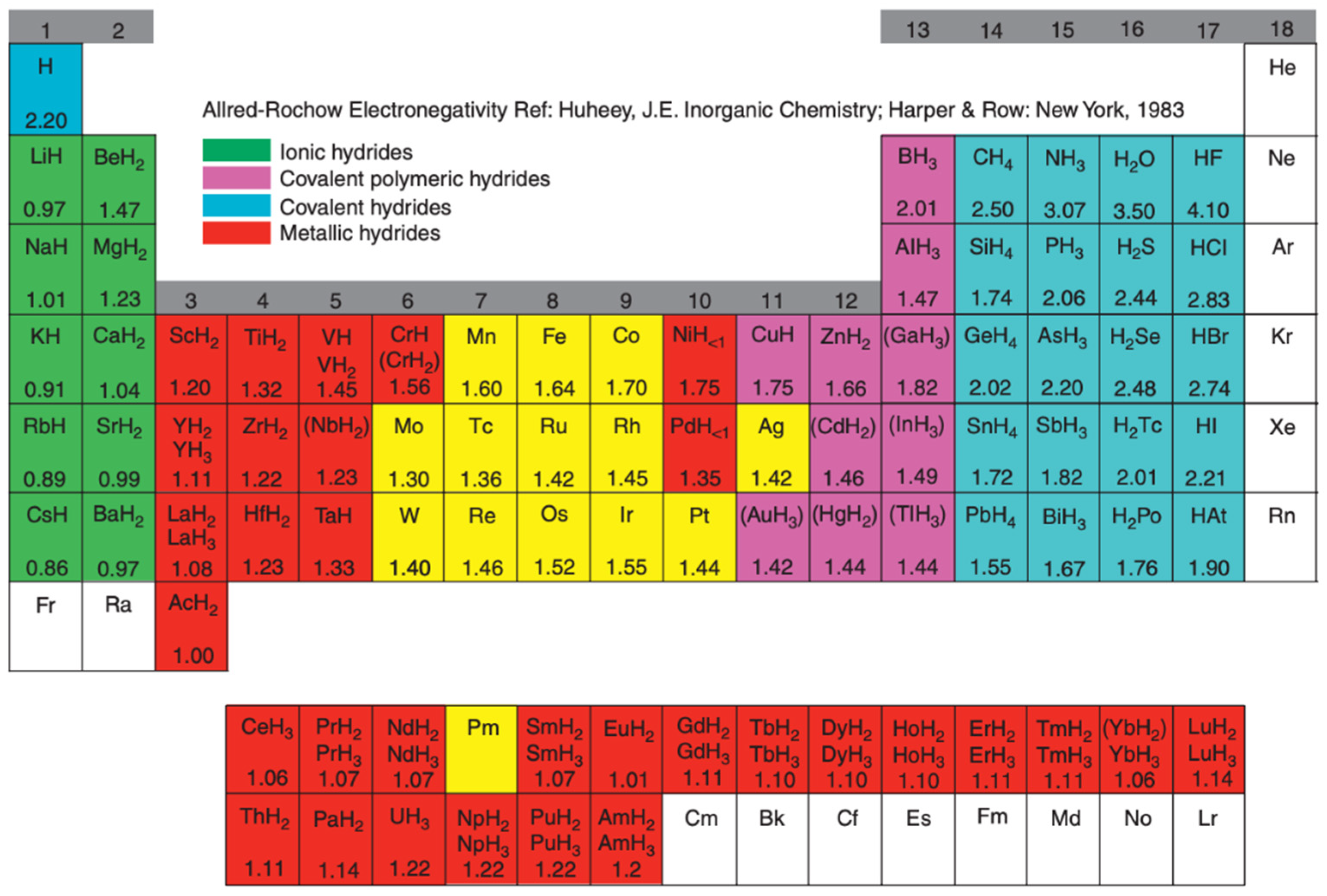
2.2. Classification
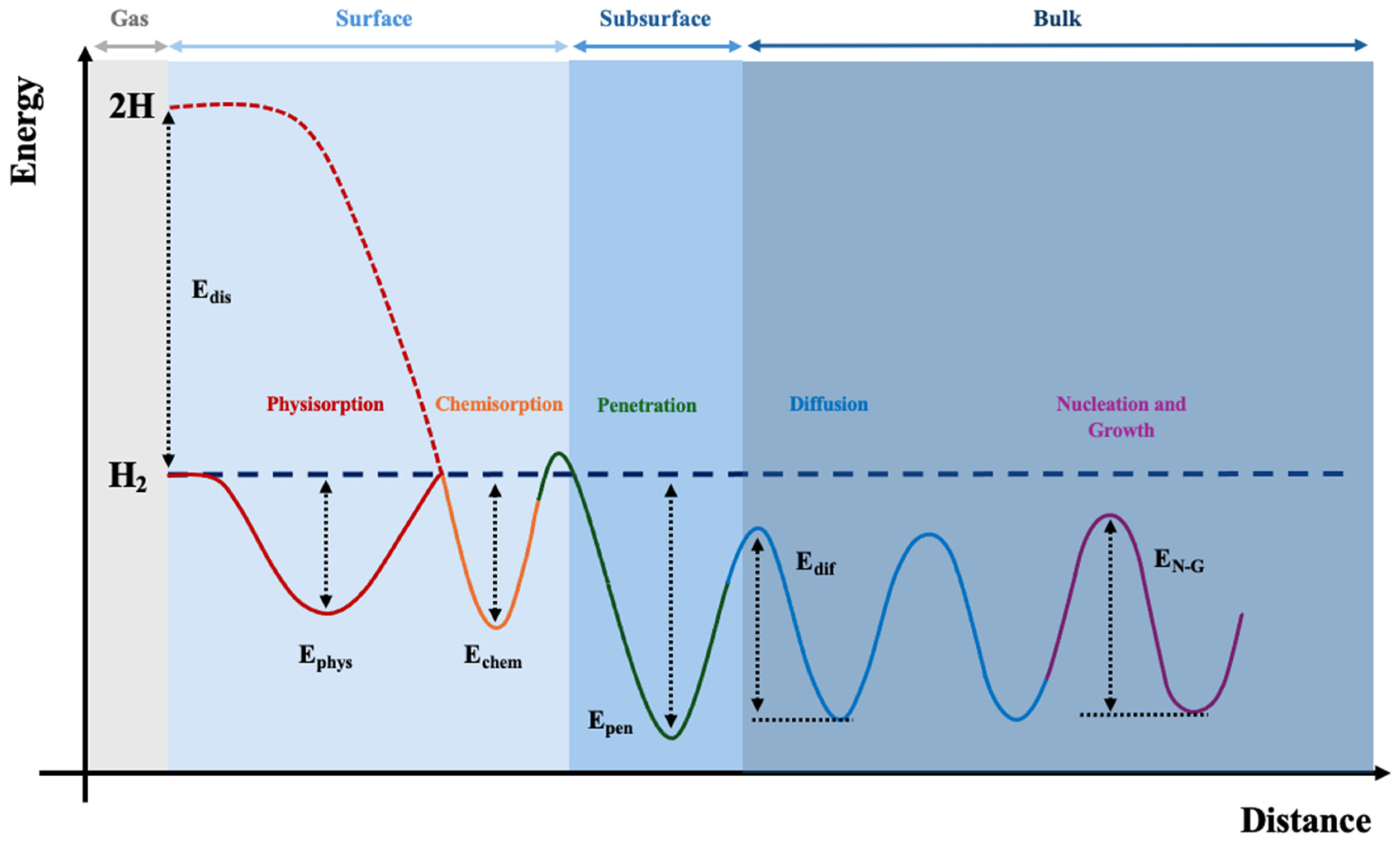
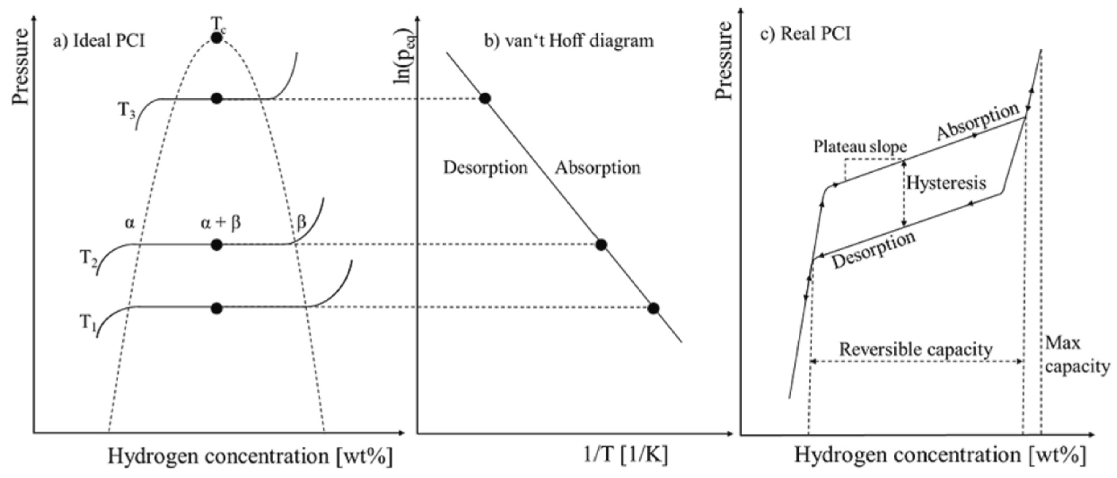
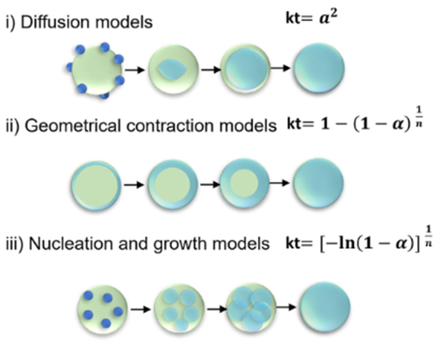
2.3. Thermodynamics and Kinetics
2.4. Physical and Thermophysical Properties
2.5. Hydride Based H2 Storage Systems
3. Thermal Energy Storage (TES)
3.1. Types of TES and Working Principle
- Capacity: defines the energy stored in the system and varies with the size, storage technology and storage medium;
- Gravimetric and/or volumetric energy density: defines the amount of energy that the material can store per unit of mass or per unit of volume, respectively;
- Power: defines how quickly the stored energy in the system can be charged or discharged;
- Efficiency: defined as the ratio between the energy made available to use, and the energy needed to charge the system. This value quantifies the losses during the charge/discharge cycles;
- Storage period: defines how long the energy can be stored;
- Charge and discharge time: defines how long a system takes to charge or discharge;
- Cost: can be defined in terms of the cost of stored energy (€/kWh) or power (€/kW) and depends on the specific configuration of the implemented system, i.e., its CAPEX and OPEX values;
- Environmental impact: refers to considerations regarding the production of the material and the operation of the plant, or the implementation of the TES technology, that should be taken into account;
- Mechanical and chemical stability: this parameter affects not only the associated costs but also has implications on the environmental impact due to the potentially lower lifetime of the material/plant;
- System complexity: this parameter can influence both CAPEX and OPEX as well as the flexibility and reliability of a given TES technology.
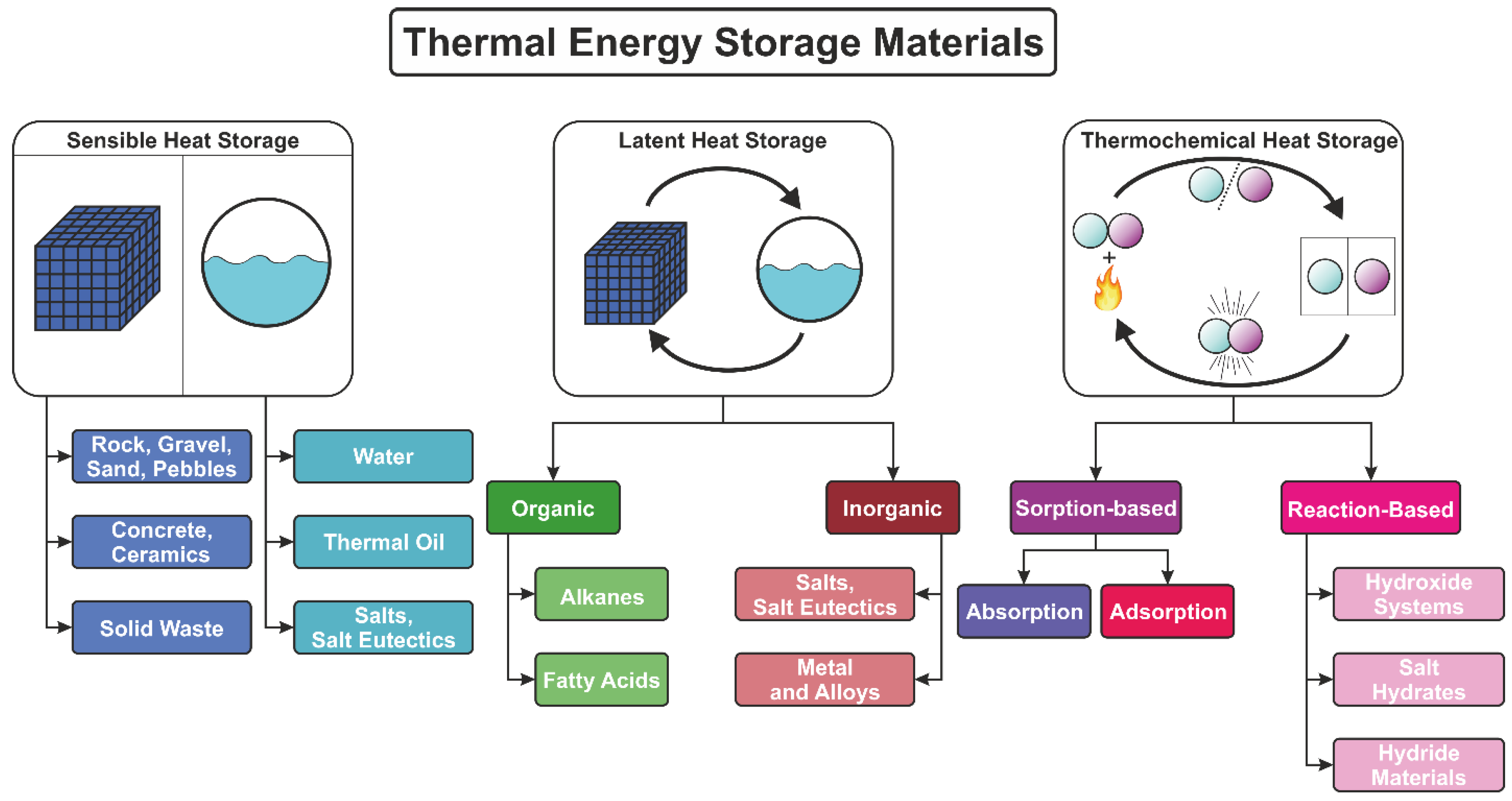
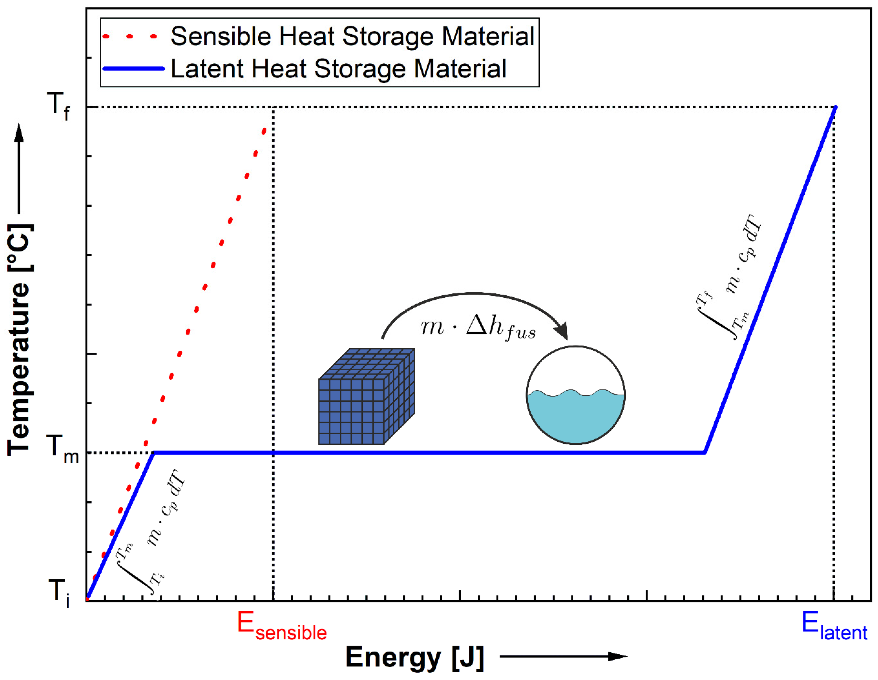
3.1.1. Sensible Heat Storage
3.1.2. Rocks, Pebbles, Sand, and Gravel
3.1.3. Concrete and Ceramic Materials
3.1.4. Solid Waste Materials
3.1.5. Water
3.1.6. Thermal Oils
3.1.7. Salts and Salt Eutectics (as Sensible Heat Storage)
3.1.8. Latent Heat Storage
3.1.9. Alkanes
3.1.10. Fatty Acids
3.1.11. Salts and Salt Eutectics (as Latent Heat Storage)
3.1.12. Metals and Alloys
3.1.13. Thermochemical Heat Storage
3.1.14. Hydroxide Systems
3.1.15. Salt Hydrates
3.1.16. Hydride Materials
4. H2-Storage Systems Coupled with TES
- Power Generation: Surplus electricity produced from both renewable or non-renewable sources during low-demand periods could be converted to H2 via an electrolyzer and stored in MH–TES systems for posterior grid load balancing in periods of peak demand. Waste heat from combined heat and power (CHP) plants could also be stored, using systems based on metal hydride pairs [243]. The incorporation of a TES system not only minimizes the need of additional energy inputs, but also allows for the subsequent re-conversion of hydrogen into electricity in times of the day where the processes that would otherwise provide heat for H2 desorption are not operating. The application of MH–TES solutions is particularly attractive nowadays due to the ongoing switch to H2 gas turbines.
- Industrial Processes and Waste Heat Recovery: Industries that produce or consume substantial amounts of either heat or hydrogen, such as the cement, petrochemical, glass, or steel industries, could integrate MH–TES systems and benefit from them in several ways. Waste heat from industrial unit operations could be captured by installed MH–TES systems and stored for later use in different processes. Alternatively, the heat generated during hydrogen absorption reactions can be leveraged through the use of TES materials and repurposed in other industrial operations. Processes that require molecular hydrogen could also directly obtain it from nearby MH tanks. On top of that, the incorporation of TES material might simultaneously guarantee a steady supply of H2 for industrial operations, and benefit the system’s overall energy efficiency, since TES materials can be used to control the temperature of the MH vessel, and therefore the rate of release of H2 can be adjusted to meet the required inputs.
- District Heating and Cooling: MH–TES systems could be employed in district heating networks. Waste thermal energy generated by district power plants or by day-to-day residential activities can be used to operate MH heat pumps based on coupled MH pairs, and subsequently, either cool or provide heating for homes. This heat-pump concept has already been studied by Kumar et al. [244]. The benefit of including TES materials in these devices, similarly to other applications, would be to provide a more careful control of the H2 release and uptake by each of the MH beds, and thus allow for the fine tuning of at home heating/cooling.
4.1. Metal Hydride: Sensible Thermal Energy Storage
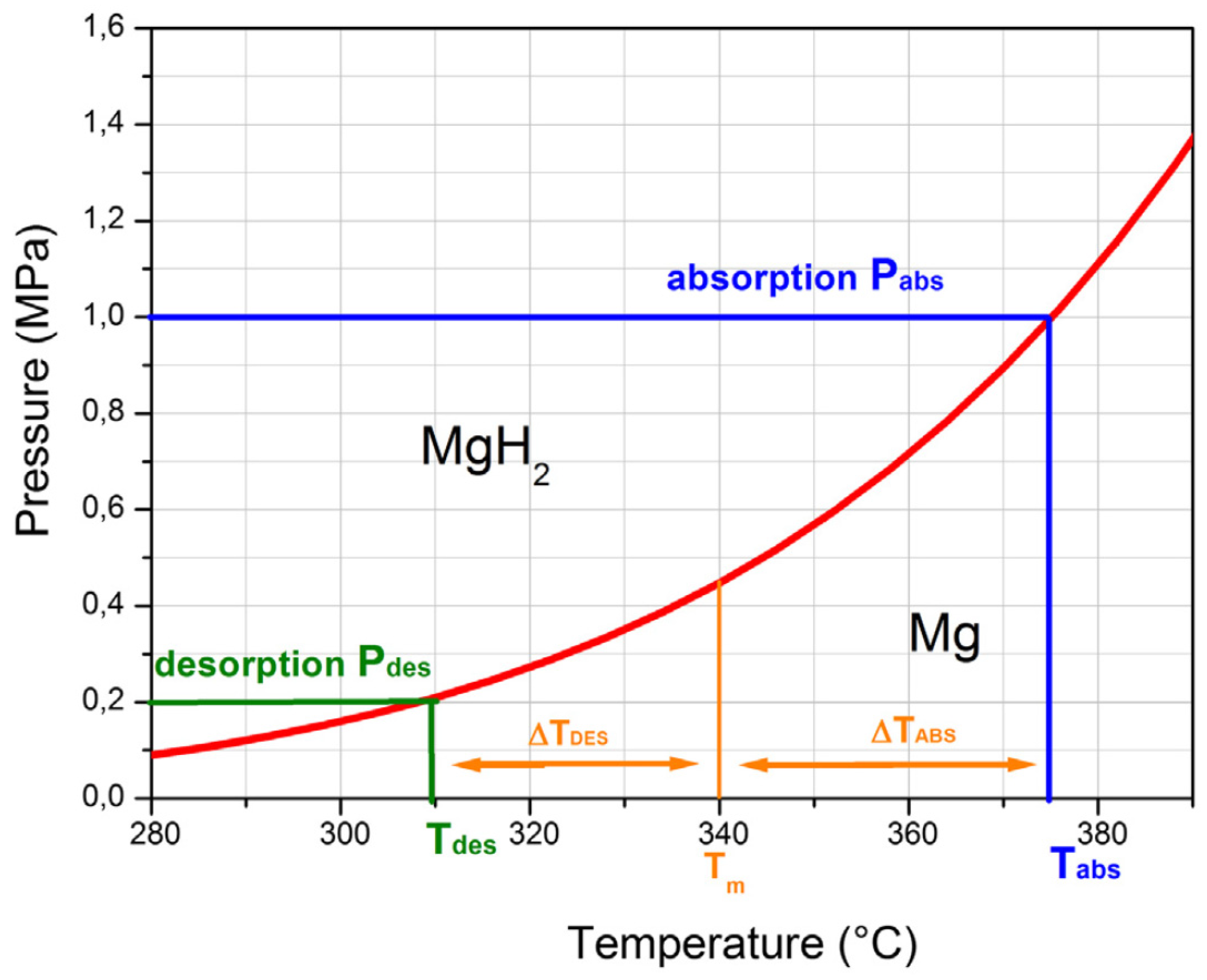
4.2. Metal Hydride: Latent Thermal Energy Storage
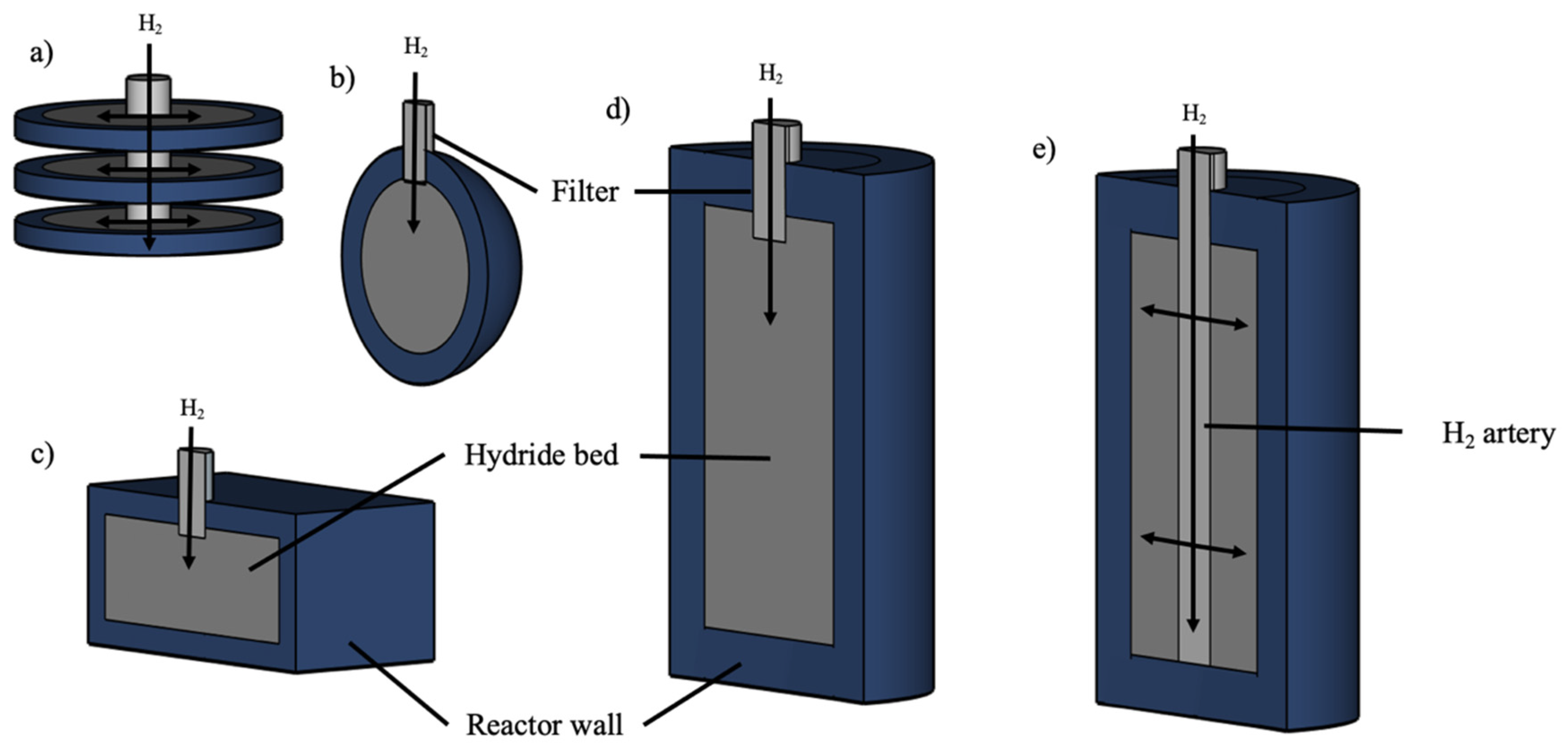
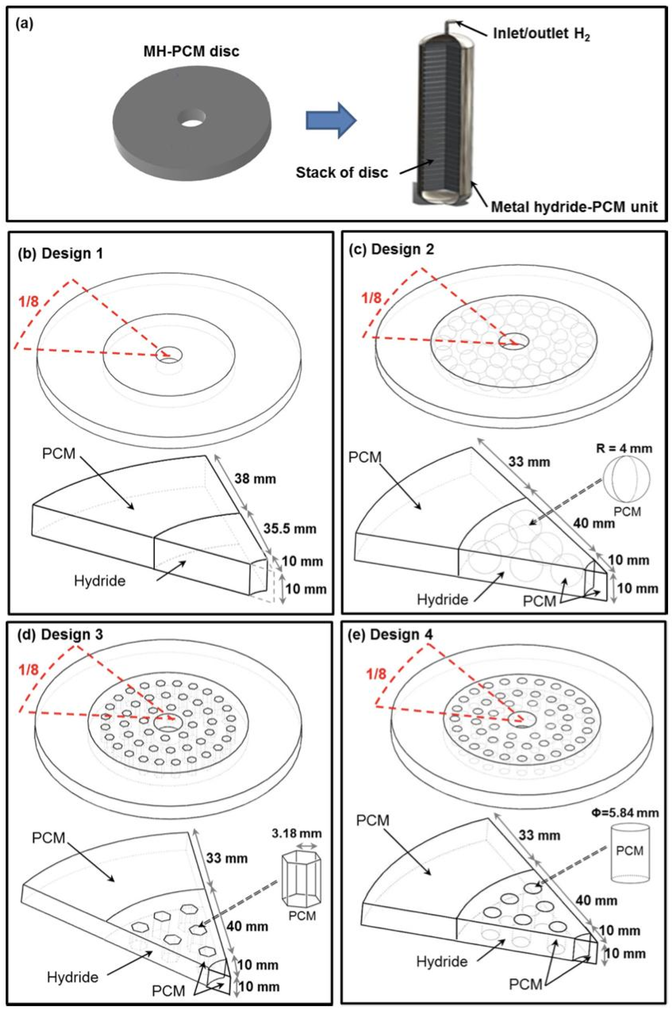
- Design 1: A basic configuration with a disk of Mg2Ni alloy surrounded by PCM stacked on a central filter tube.
- Design 2: Similarly to Design 1 but with 48 encapsulated spherical shells filled with PCM, arranged concentrically inside the MH bed.
- Design 3: Each spherical shell in Design 2 is replaced by a hexagonal tube filled with PCM.
- Design 4: Each hexagonal tube in Design 3 is replaced by a cylindrical tube filled with PCM.
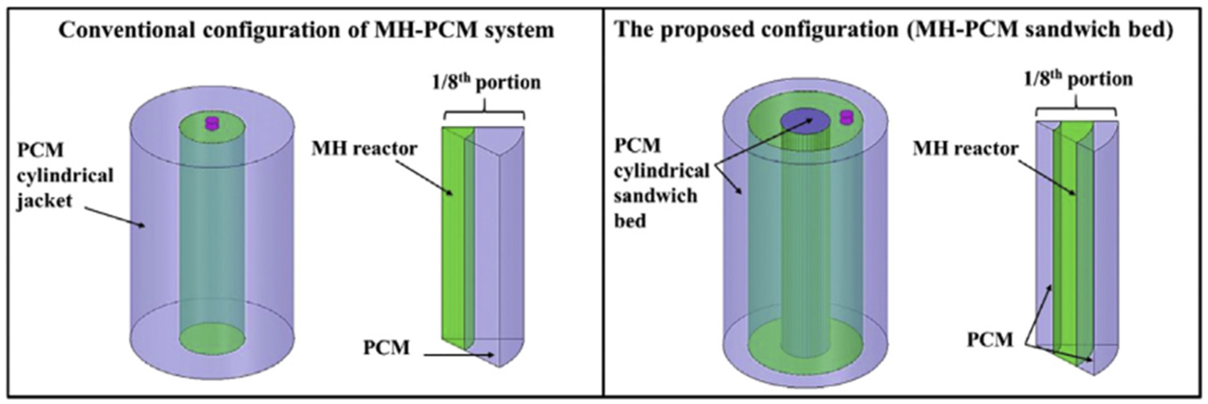
- Design 1: A metal hydride reactor was surrounded by a single cylindrical jacket packed with the PCM. The heat exchange took place at the interface between the hydride reactor and the PCM jacket.
- Design 2: A metal hydride reactor was enclosed by PCM in a cylindrical sandwich bed, which increased the heat transfer area by adding more interfaces between the MH reactor and the PCM.
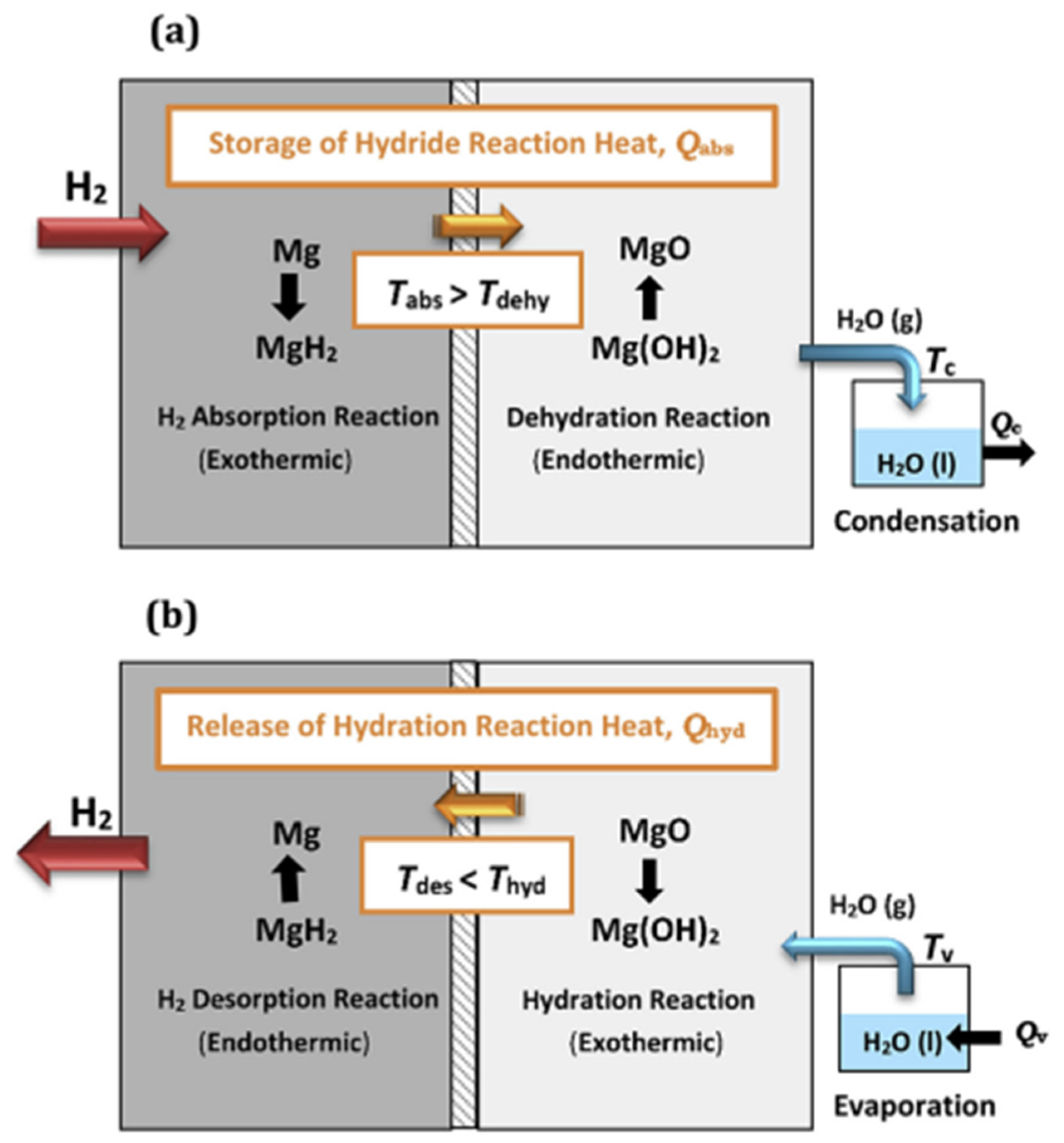
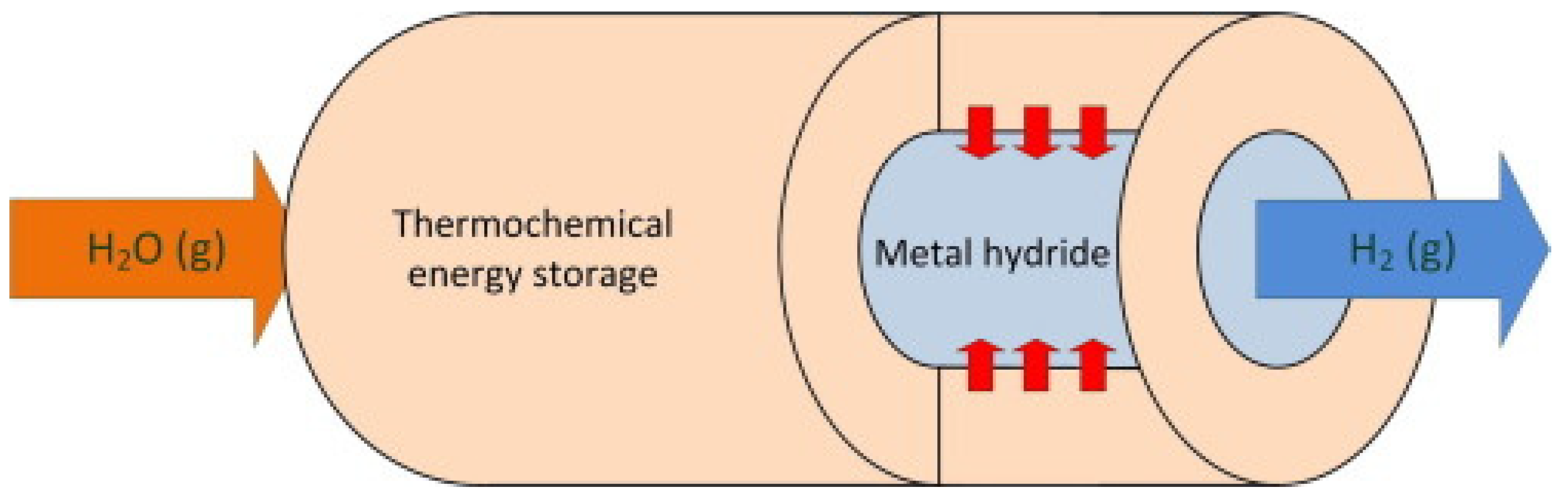
4.3. Metal Hydride: Thermochemical Thermal Energy Storage
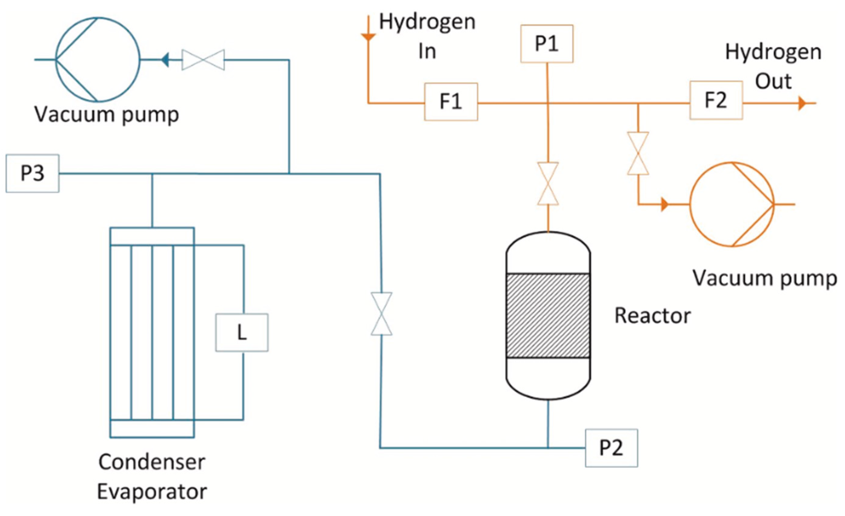
- Water vapor infrastructure, where water vapor was supplied or withdrawn using a tube bundle that acted as an evaporator/condenser, regulated by thermal oils. This allowed the control of the water vapor pressure in the reactor, and the measurement of the reacted fraction of the thermochemical system via liquid level changes and pressure sensors.
- The hydrogen infrastructure, where hydrogen was supplied or withdrawn from the reactor using volume flow controllers.
- The reactor, which consisted of a double-walled tube with the metal hydride in the form of 300 mm diameter pellets located in the inner tube, and Mg(OH)2 powder in the outer tube for heat absorption. The reactor included thermocouples for temperature monitoring and was designed to exclude mass transfer limitations.
5. Future Developments
5.1. Material and System Development
5.2. Economic Feasibility
6. Conclusions
Author Contributions
Funding
Conflicts of Interest
References
- IEA Report Electricity. 2024. Available online: https://www.iea.org/reports/electricity-2024 (accessed on 13 September 2024).
- IEA Report World Energy Outlook. 2023. Available online: https://www.iea.org/reports/world-energy-outlook-2023 (accessed on 13 September 2024).
- Møller, K.T.; Jensen, T.R.; Akiba, E.; Li, H. Hydrogen—A Sustainable Energy Carrier. Prog. Nat. Sci. Mater. Int. 2017, 27, 34–40. [Google Scholar] [CrossRef]
- Scita, R.; Raimondi, P.P.; Noussan, M. Green Hydrogen: The Holy Grail of Decarbonisation? An Analysis of the Technical and Geopolitical Implications of the Future Hydrogen Economy; Fondazione Eni Enrico Mattei (FEEM): Milan, Italy, 2020. [Google Scholar] [CrossRef]
- AlZohbi, G.; Almoaikel, A.; AlShuhail, L. An Overview on the Technologies Used to Store Hydrogen. Energy Rep. 2023, 9, 28–34. [Google Scholar] [CrossRef]
- Drawer, C.; Lange, J.; Kaltschmitt, M. Metal Hydrides for Hydrogen Storage—Identification and Evaluation of Stationary and Transportation Applications. J. Energy Storage 2024, 77, 109988. [Google Scholar] [CrossRef]
- Chatterjee, S.; Parsapur, R.K.; Huang, K.-W. Limitations of Ammonia as a Hydrogen Energy Carrier for the Transportation Sector. ACS Energy Lett. 2021, 6, 4390–4394. [Google Scholar] [CrossRef]
- Hirscher, M. (Ed.) Handbook of Hydrogen Storage: New Materials for Future Energy Storage; Wiley-VCH: Weinheim, Germany, 2010; ISBN 978-3-527-32273-2. [Google Scholar]
- Kukkapalli, V.K.; Kim, S.; Thomas, S.A. Thermal Management Techniques in Metal Hydrides for Hydrogen Storage Applications: A Review. Energies 2023, 16, 3444. [Google Scholar] [CrossRef]
- Klopčič, N.; Grimmer, I.; Winkler, F.; Sartory, M.; Trattner, A. A Review on Metal Hydride Materials for Hydrogen Storage. J. Energy Storage 2023, 72, 108456. [Google Scholar] [CrossRef]
- Sandrock, G. A Panoramic Overview of Hydrogen Storage Alloys from a Gas Reaction Point of View. J. Alloys Compd. 1999, 293–295, 877–888. [Google Scholar] [CrossRef]
- Liu, J.; Yang, F.; Wu, Z.; Zhang, Z. A Review of Thermal Coupling System of Fuel Cell-Metal Hydride Tank: Classification, Control Strategies, and Prospect in Distributed Energy System. Int. J. Hydrogen Energy 2024, 51, 274–289. [Google Scholar] [CrossRef]
- Cetinkaya, S.A.; Disli, T.; Soyturk, G.; Kizilkan, O.; Colpan, C.O. A Review on Thermal Coupling of Metal Hydride Storage Tanks with Fuel Cells and Electrolyzers. Energies 2022, 16, 341. [Google Scholar] [CrossRef]
- Nguyen, H.Q.; Shabani, B. Proton Exchange Membrane Fuel Cells Heat Recovery Opportunities for Combined Heating/Cooling and Power Applications. Energy Convers. Manag. 2020, 204, 112328. [Google Scholar] [CrossRef]
- Somo, T.R.; Maponya, T.C.; Davids, M.W.; Hato, M.J.; Lototskyy, M.V.; Modibane, K.D. A Comprehensive Review on Hydrogen Absorption Behaviour of Metal Alloys Prepared through Mechanical Alloying. Metals 2020, 10, 562. [Google Scholar] [CrossRef]
- Alapati, S.V.; Karl Johnson, J.; Sholl, D.S. Using First Principles Calculations to Identify New Destabilized Metal Hydride Reactions for Reversible Hydrogen Storage. Phys. Chem. Chem. Phys. 2007, 9, 1438. [Google Scholar] [CrossRef]
- Salman, M.S.; Pratthana, C.; Lai, Q.; Wang, T.; Rambhujun, N.; Srivastava, K.; Aguey-Zinsou, K.-F. Catalysis in Solid Hydrogen Storage: Recent Advances, Challenges, and Perspectives. Energy Technol. 2022, 10, 2200433. [Google Scholar] [CrossRef]
- Meyers, R.A. (Ed.) Encyclopedia of Physical Science and Technology, 3rd ed.; Academic Press: San Diego, CA, USA, 2002; ISBN 978-0-12-227410-7. [Google Scholar]
- Huston, E.L.; Sandrock, G.D. Engineering Properties of Metal Hydrides. J. Common. Met. 1980, 74, 435–443. [Google Scholar] [CrossRef]
- Graetz, J. Metastable Metal Hydrides for Hydrogen Storage. ISRN Mater. Sci. 2012, 2012, 863025. [Google Scholar] [CrossRef]
- Sakintuna, B.; Lamaridarkrim, F.; Hirscher, M. Metal Hydride Materials for Solid Hydrogen Storage: A Review. Int. J. Hydrogen Energy 2007, 32, 1121–1140. [Google Scholar] [CrossRef]
- Poeppelmeier, K.R.; Reedijk, J. Comprehensive Inorganic Chemistry II: From Elements to Applications; Elsevier: Amsterdam, The Netherlands, 2013; ISBN 978-0-08-096529-1. [Google Scholar]
- Züttel, A. FUELS—HYDROGEN STORAGE|Hydrides. In Encyclopedia of Electrochemical Power Sources; Elsevier: Amsterdam, The Netherlands, 2009; pp. 440–458. ISBN 978-0-444-52745-5. [Google Scholar]
- Huheey, J.E. Inorganic Chemistry: Principles of Structure and Reactivity, 3rd ed.; Harper & Row: New York, NY, USA, 1983; ISBN 978-0-06-042987-4. [Google Scholar]
- Lys, A.; Fadonougbo, J.O.; Faisal, M.; Suh, J.-Y.; Lee, Y.-S.; Shim, J.-H.; Park, J.; Cho, Y.W. Enhancing the Hydrogen Storage Properties of AxBy Intermetallic Compounds by Partial Substitution: A Short Review. Hydrogen 2020, 1, 38–63. [Google Scholar] [CrossRef]
- Liu, W.; Webb, C.J.; Gray, E.M. Review of Hydrogen Storage in AB 3 Alloys Targeting Stationary Fuel Cell Applications. Int. J. Hydrogen Energy 2016, 41, 3485–3507. [Google Scholar] [CrossRef]
- Marinelli, M.; Santarelli, M. Hydrogen Storage Alloys for Stationary Applications. J. Energy Storage 2020, 32, 101864. [Google Scholar] [CrossRef]
- Abdin, Z.; Tang, C.; Liu, Y.; Catchpole, K. Current State and Challenges for Hydrogen Storage Technologies. In Towards Hydrogen Infrastructure; Elsevier: Amsterdam, The Netherlands, 2024; pp. 101–132. ISBN 978-0-323-95553-9. [Google Scholar]
- Andersson, J.; Grönkvist, S. Large-Scale Storage of Hydrogen. Int. J. Hydrogen Energy 2019, 44, 11901–11919. [Google Scholar] [CrossRef]
- Wang, L.; Aguey-Zinsou, K.-F. Synthesis of LiAlH4 Nanoparticles Leading to a Single Hydrogen Release Step upon Ti Coating. Inorganics 2017, 5, 38. [Google Scholar] [CrossRef]
- Chen, Z.; Ma, Z.; Zheng, J.; Li, X.; Akiba, E.; Li, H.-W. Perspectives and Challenges of Hydrogen Storage in Solid-State Hydrides. Chin. J. Chem. Eng. 2021, 29, 1–12. [Google Scholar] [CrossRef]
- Puszkiel, J.; Garroni, S.; Milanese, C.; Gennari, F.; Klassen, T.; Dornheim, M.; Pistidda, C. Tetrahydroborates: Development and Potential as Hydrogen Storage Medium. Inorganics 2017, 5, 74. [Google Scholar] [CrossRef]
- Bogdanović, B.; Reiser, A.; Schlichte, K.; Spliethoff, B.; Tesche, B. Thermodynamics and Dynamics of the Mg–Fe–H System and Its Potential for Thermochemical Thermal Energy Storage. J. Alloys Compd. 2002, 345, 77–89. [Google Scholar] [CrossRef]
- Thiangviriya, S.; Plerdsranoy, P.; Hagenah, A.; Le, T.T.; Kidkhunthod, P.; Utke, O.; Dornheim, M.; Klassen, T.; Pistidda, C.; Utke, R. Effects of Ni-Loading Contents on Dehydrogenation Kinetics and Reversibility of Mg2FeH6. Int. J. Hydrogen Energy 2021, 46, 32099–32109. [Google Scholar] [CrossRef]
- Züttel, A.; Borgschulte, A.; Orimo, S.-I. Tetrahydroborates as New Hydrogen Storage Materials. Scr. Mater. 2007, 56, 823–828. [Google Scholar] [CrossRef]
- Puszkiel, J.; Gasnier, A.; Amica, G.; Gennari, F. Tuning LiBH4 for Hydrogen Storage: Destabilization, Additive, and Nanoconfinement Approaches. Molecules 2019, 25, 163. [Google Scholar] [CrossRef]
- Mauron, P.; Buchter, F.; Friedrichs, O.; Remhof, A.; Bielmann, M.; Zwicky, C.N.; Züttel, A. Stability and Reversibility of LiBH4. J. Phys. Chem. B 2008, 112, 906–910. [Google Scholar] [CrossRef]
- Ali, N.A.; Sazelee, N.A.; Ismail, M. An Overview of Reactive Hydride Composite (RHC) for Solid-State Hydrogen Storage Materials. Int. J. Hydrogen Energy 2021, 46, 31674–31698. [Google Scholar] [CrossRef]
- Vajo, J.J.; Skeith, S.L.; Mertens, F. Reversible Storage of Hydrogen in Destabilized LiBH4. J. Phys. Chem. B 2005, 109, 3719–3722. [Google Scholar] [CrossRef]
- Ding, Z.; Li, S.; Zhou, Y.; Chen, Z.; Yang, W.; Ma, W.; Shaw, L. LiBH4 for Hydrogen Storage—New Perspectives. Nano Mater. Sci. 2020, 2, 109–119. [Google Scholar] [CrossRef]
- Neves, A.M.; Puszkiel, J.; Capurso, G.; Bellosta Von Colbe, J.M.; Milanese, C.; Dornheim, M.; Klassen, T.; Jepsen, J. Modeling the Kinetic Behavior of the Li-RHC System for Energy-Hydrogen Storage: (I) Absorption. Int. J. Hydrogen Energy 2021, 46, 32110–32125. [Google Scholar] [CrossRef]
- Neves, A.M.; Puszkiel, J.; Capurso, G.; Bellosta Von Colbe, J.M.; Klassen, T.; Jepsen, J. Development of a New Approach for the Kinetic Modeling of the Lithium Reactive Hydride Composite (Li-RHC) for Hydrogen Storage under Desorption Conditions. Chem. Eng. J. 2023, 464, 142274. [Google Scholar] [CrossRef]
- Laughlin, D.E.; Hono, K. Physical Metallurgy, 5th ed.; Elsevier: Amsterdam, The Netherlands, 2014; ISBN 978-0-444-53770-6. [Google Scholar]
- Aguey-Zinsou, K.-F.; Ares-Fernández, J.-R. Hydrogen in Magnesium: New Perspectives toward Functional Stores. Energy Environ. Sci. 2010, 3, 526. [Google Scholar] [CrossRef]
- Li, Q.; Lu, Y.; Luo, Q.; Yang, X.; Yang, Y.; Tan, J.; Dong, Z.; Dang, J.; Li, J.; Chen, Y.; et al. Thermodynamics and Kinetics of Hydriding and Dehydriding Reactions in Mg-Based Hydrogen Storage Materials. J. Magnes. Alloys 2021, 9, 1922–1941. [Google Scholar] [CrossRef]
- Siegmann, H.C.; Schlapbach, L.; Brundle, C.R. Self-Restoring of the Active Surface in the Hydrogen Sponge La Ni5. Phys. Rev. Lett. 1978, 40, 972–975. [Google Scholar] [CrossRef]
- Kirchheim, R.; Pundt, A. Hydrogen in Metals. In Physical Metallurgy; Elsevier: Amsterdam, The Netherlands, 2014; pp. 2597–2705. ISBN 978-0-444-53770-6. [Google Scholar]
- Lototskyy, M.V.; Tarasov, B.P.; Yartys, V.A. Gas-Phase Applications of Metal Hydrides. J. Energy Storage 2023, 72, 108165. [Google Scholar] [CrossRef]
- Bloch, J.; Mintz, M.H. Kinetics and Mechanisms of Metal Hydrides Formation—A Review. J. Alloys Compd. 1997, 253–254, 529–541. [Google Scholar] [CrossRef]
- Atilio Puszkiel, J. Tailoring the Kinetic Behavior of Hydride Forming Materials for Hydrogen Storage. In Gold Nanoparticles—Reaching New Heights; Rahman, M., Mohammed Asiri, A., Eds.; IntechOpen: London, UK, 2019; ISBN 978-1-78984-998-1. [Google Scholar]
- Campo, M.; Tanaka, A.; Mendes, A.; Sousa, J.M. Characterization of Membranes for Energy and Environmental Applications. In Advanced Membrane Science and Technology for Sustainable Energy and Environmental Applications; Elsevier: Amsterdam, The Netherlands, 2011; pp. 56–89. ISBN 978-1-84569-969-7. [Google Scholar]
- Wilde, G. (Ed.) Nanostructured Materials. In Frontiers of Nanoscience, 1st ed.; Elsevier: Oxford, UK; Boston, MA, USA, 2009; ISBN 978-0-08-044965-4. [Google Scholar]
- Balasubramaniam, R. Hysteresis in Metal–Hydrogen Systems. J. Alloys Compd. 1997, 253–254, 203–206. [Google Scholar] [CrossRef]
- Qian, S.; Northwood, D. Hysteresis in Metal-Hydrogen Systems: A Critical Review of the Experimental Observations and Theoretical Models. Int. J. Hydrogen Energy 1988, 13, 25–35. [Google Scholar] [CrossRef]
- Flanagan, T.B.; Clewley, J.D. Hysteresis in Metal Hydrides. J. Common. Met. 1982, 83, 127–141. [Google Scholar] [CrossRef]
- Schwarz, R.B.; Khachaturyan, A.G. Thermodynamics of Open Two-Phase Systems with Coherent Interfaces: Application to Metal–Hydrogen Systems. Acta Mater. 2006, 54, 313–323. [Google Scholar] [CrossRef]
- Wang, X.; Suda, S. Reaction Kinetics of Hydrogen-Metal Hydride Systems. Int. J. Hydrogen Energy 1990, 15, 569–577. [Google Scholar] [CrossRef]
- Pang, Y.; Li, Q. A Review on Kinetic Models and Corresponding Analysis Methods for Hydrogen Storage Materials. Int. J. Hydrogen Energy 2016, 41, 18072–18087. [Google Scholar] [CrossRef]
- Murdoch, J.R. What Is the Rate-Limiting Step of a Multistep Reaction? J. Chem. Educ. 1981, 58, 32. [Google Scholar] [CrossRef]
- Wu, H. Strategies for the Improvement of the Hydrogen Storage Properties of Metal Hydride Materials. ChemPhysChem 2008, 9, 2157–2162. [Google Scholar] [CrossRef]
- Dornheim, M. Thermodynamics of Metal Hydrides: Tailoring Reaction Enthalpies of Hydrogen Storage Materials. In Thermodynamics—Interaction Studies—Solids, Liquids and Gases; Moreno Pirajn, J.C., Ed.; InTech: Tokyo, Japan, 2011; ISBN 978-953-307-563-1. [Google Scholar]
- Ulmer, U.; Oertel, D.; Diemant, T.; Bonatto Minella, C.; Bergfeldt, T.; Dittmeyer, R.; Behm, R.J.; Fichtner, M. Performance Improvement of V–Fe–Cr–Ti Solid State Hydrogen Storage Materials in Impure Hydrogen Gas. ACS Appl. Mater. Interfaces 2018, 10, 1662–1671. [Google Scholar] [CrossRef]
- Zhang, L.; Sun, Z.; Yao, Z.; Yang, L.; Yan, N.; Lu, X.; Xiao, B.; Zhu, X.; Chen, L. Excellent Catalysis of Mn3O4 Nanoparticles on the Hydrogen Storage Properties of MgH2: An Experimental and Theoretical Study. Nanoscale Adv. 2020, 2, 1666–1675. [Google Scholar] [CrossRef]
- Ali, N.A.; Idris, N.H.; Sazelee, N.A.; Yahya, M.S.; Yap, F.A.H.; Ismail, M. Catalytic Effects of MgFe2O4 Addition on the Dehydrogenation Properties of LiAlH4. Int. J. Hydrogen Energy 2019, 44, 28227–28234. [Google Scholar] [CrossRef]
- Dematteis, E.M.; Berti, N.; Cuevas, F.; Latroche, M.; Baricco, M. Substitutional Effects in TiFe for Hydrogen Storage: A Comprehensive Review. Mater. Adv. 2021, 2, 2524–2560. [Google Scholar] [CrossRef]
- Lozano, G.A.; Bellosta Von Colbe, J.M.; Klassen, T.; Dornheim, M. Transport Phenomena versus Intrinsic Kinetics: Hydrogen Sorption Limiting Sub-Process in Metal Hydride Beds. Int. J. Hydrogen Energy 2014, 39, 18952–18957. [Google Scholar] [CrossRef]
- Stampfer, J.F.; Holley, C.E.; Suttle, J.F. The Magnesium-Hydrogen System1–3. J. Am. Chem. Soc. 1960, 82, 3504–3508. [Google Scholar] [CrossRef]
- Bogdanović, B.; Bohmhammel, K.; Christ, B.; Reiser, A.; Schlichte, K.; Vehlen, R.; Wolf, U. Thermodynamic Investigation of the Magnesium–Hydrogen System. J. Alloys Compd. 1999, 282, 84–92. [Google Scholar] [CrossRef]
- Dematteis, E.M.; Dreistadt, D.M.; Capurso, G.; Jepsen, J.; Cuevas, F.; Latroche, M. Fundamental Hydrogen Storage Properties of TiFe-Alloy with Partial Substitution of Fe by Ti and Mn. J. Alloys Compd. 2021, 874, 159925. [Google Scholar] [CrossRef]
- Luo, W.; Craft, A.; Kuji, T.; Chung, H.S.; Flanagan, T.B. Thermodynamic Characterization of the ZrNi H System by Reaction Calorimetry and P-c-t Measurements. J. Common. Met. 1990, 162, 251–266. [Google Scholar] [CrossRef]
- Kölbig, M.; Bürger, I.; Linder, M. Characterization of Metal Hydrides for Thermal Applications in Vehicles below 0 °C. Int. J. Hydrogen Energy 2019, 44, 4878–4888. [Google Scholar] [CrossRef]
- Khan, D.; Zou, J.; Zeng, X.; Ding, W. Hydrogen Storage Properties of Nanocrystalline Mg2Ni Prepared from Compressed 2MgH2-Ni Powder. Int. J. Hydrogen Energy 2018, 43, 22391–22400. [Google Scholar] [CrossRef]
- Zhu, Z.; Zhu, S.; Lu, H.; Wu, J.; Yan, K.; Cheng, H.; Liu, J. Stability of LaNi5-Co Alloys Cycled in Hydrogen—Part 1 Evolution in Gaseous Hydrogen Storage Performance. Int. J. Hydrogen Energy 2019, 44, 15159–15172. [Google Scholar] [CrossRef]
- Klyamkin, S.N.; Zakharkina, N.S. Hysteresis and Related Irreversible Phenomena in CeNi5-Based Intermetallic Hydrides. J. Alloys Compd. 2003, 361, 200–205. [Google Scholar] [CrossRef]
- Bellosta Von Colbe, J.; Ares, J.-R.; Barale, J.; Baricco, M.; Buckley, C.; Capurso, G.; Gallandat, N.; Grant, D.M.; Guzik, M.N.; Jacob, I.; et al. Application of Hydrides in Hydrogen Storage and Compression: Achievements, Outlook and Perspectives. Int. J. Hydrogen Energy 2019, 44, 7780–7808. [Google Scholar] [CrossRef]
- Bogdanović, B.; Brand, R.A.; Marjanović, A.; Schwickardi, M.; Tölle, J. Metal-Doped Sodium Aluminium Hydrides as Potential New Hydrogen Storage Materials. J. Alloys Compd. 2000, 302, 36–58. [Google Scholar] [CrossRef]
- Martelli, P.; Caputo, R.; Remhof, A.; Mauron, P.; Borgschulte, A.; Züttel, A. Stability and Decomposition of NaBH4. J. Phys. Chem. C 2010, 114, 7173–7177. [Google Scholar] [CrossRef]
- Puszkiel, J.A.; Larochette, P.A.; Gennari, F.C. Thermodynamic and Kinetic Studies of Mg–Fe–H after Mechanical Milling Followed by Sintering. J. Alloys Compd. 2008, 463, 134–142. [Google Scholar] [CrossRef]
- Chen, P.; Xiong, Z.; Luo, J.; Lin, J.; Tan, K.L. Interaction of Hydrogen with Metal Nitrides and Imides. Nature 2002, 420, 302–304. [Google Scholar] [CrossRef] [PubMed]
- Kojima, Y.; Kawai, Y. IR Characterizations of Lithium Imide and Amide. J. Alloys Compd. 2005, 395, 236–239. [Google Scholar] [CrossRef]
- Puszkiel, J.A.; Castro Riglos, M.V.; Ramallo-López, J.M.; Mizrahi, M.; Karimi, F.; Santoru, A.; Hoell, A.; Gennari, F.C.; Larochette, P.A.; Pistidda, C.; et al. A Novel Catalytic Route for Hydrogenation–Dehydrogenation of 2LiH + MgB2 via In Situ Formed Core–Shell Lix TiO2 Nanoparticles. J. Mater. Chem. A 2017, 5, 12922–12933. [Google Scholar] [CrossRef]
- Ye, J.; Li, Z.; Zhang, L.; Wang, S.; Jiang, L. Measurement and the Improvement of Effective Thermal Conductivity for a Metal Hydride Bed—A Review. RSC Adv. 2022, 12, 25722–25743. [Google Scholar] [CrossRef]
- Broom, D.P. Hydrogen Storage Materials: The Characterisation of Their Storage Properties; Green Energy and Technology; Springer: London, UK; Heidelberg, Germany, 2011; ISBN 978-0-85729-220-9. [Google Scholar]
- Jepsen, J.; Milanese, C.; Girella, A.; Lozano, G.A.; Pistidda, C.; Bellosta Von Colbe, J.M.; Marini, A.; Klassen, T.; Dornheim, M. Compaction Pressure Influence on Material Properties and Sorption Behaviour of LiBH4–MgH2 Composite. Int. J. Hydrogen Energy 2013, 38, 8357–8366. [Google Scholar] [CrossRef]
- Pohlmann, C.; Röntzsch, L.; Weißgärber, T.; Kieback, B. Heat and Gas Transport Properties in Pelletized Hydride–Graphite-Composites for Hydrogen Storage Applications. Int. J. Hydrogen Energy 2013, 38, 1685–1691. [Google Scholar] [CrossRef]
- Atalmis, G.; Sattarkhanov, K.; Kaplan, R.N.; Demiralp, M.; Kaplan, Y. The Effect of Powder and Pellet Forms of Added Metal Hydride Materials on Reaction Kinetics and Storage. Int. J. Hydrogen Energy 2024, 75, 98–105. [Google Scholar] [CrossRef]
- Lozano, G.A.; Bellosta Von Colbe, J.M.; Bormann, R.; Klassen, T.; Dornheim, M. Enhanced Volumetric Hydrogen Density in Sodium Alanate by Compaction. J. Power Sources 2011, 196, 9254–9259. [Google Scholar] [CrossRef]
- Safyari, M.; Gneiger, S.; Simson, C.; Moshtaghi, M. A New Methodology for Extra Enhancement of Hydrogen Storage Capacity of Mg–Ni Based Alloys: The Role of Gaseous O2/H2 Mixture. Int. J. Hydrogen Energy 2024, 73, 761–767. [Google Scholar] [CrossRef]
- Modi, P.; Aguey-Zinsou, K.-F. Room Temperature Metal Hydrides for Stationary and Heat Storage Applications: A Review. Front. Energy Res. 2021, 9, 616115. [Google Scholar] [CrossRef]
- Kim, D.; Kim, J.B.; Lee, J.; Lee, B.J. Measurement of Effective Thermal Conductivity of LaNi5 Powder Packed Bed. Int. J. Heat Mass Transf. 2021, 165, 120735. [Google Scholar] [CrossRef]
- Bird, J.E.; Humphries, T.D.; Paskevicius, M.; Poupin, L.; Buckley, C.E. Thermal Properties of Thermochemical Heat Storage Materials. Phys. Chem. Chem. Phys. 2020, 22, 4617–4625. [Google Scholar] [CrossRef]
- Albert, R.; Urbanczyk, R.; Felderhoff, M. Thermal Conductivity Measurements of Magnesium Hydride Powder Beds under Operating Conditions for Heat Storage Applications. Int. J. Hydrogen Energy 2019, 44, 29273–29281. [Google Scholar] [CrossRef]
- Ishido, Y.; Kawamura, M.; Ono, S. Thermal Conductivity of Magnesium-Nickel Hydride Powder Beds in a Hydrogen Atmosphere. Int. J. Hydrogen Energy 1982, 7, 173–182. [Google Scholar] [CrossRef]
- Hahne, E.; Kallweit, J.J. Thermal Conductivity of Metal Hydride Materials for Storage of Hydrogen: Experimental Investigation. Int. J. Hydrogen Energy 1998, 23, 107–114. [Google Scholar] [CrossRef]
- Suda, S.; Kobayashi, N.; Yoshida, K. Thermal Conductivity in Metal Hydride Beds. Int. J. Hydrogen Energy 1981, 6, 521–528. [Google Scholar] [CrossRef]
- Dedrick, D.E.; Kanouff, M.P.; Replogle, B.C.; Gross, K.J. Thermal Properties Characterization of Sodium Alanates. J. Alloys Compd. 2005, 389, 299–305. [Google Scholar] [CrossRef]
- Ghafir, M.F.A.; Batcha, M.F.M.; Raghavan, V.R. Prediction of the Thermal Conductivity of Metal Hydrides—The Inverse Problem. Int. J. Hydrogen Energy 2009, 34, 7125–7130. [Google Scholar] [CrossRef]
- Cheng, G.; Gan, J.; Xu, D.; Yu, A. Evaluation of Effective Thermal Conductivity in Random Packed Bed: Heat Transfer through Fluid Voids and Effect of Packing Structure. Powder Technol. 2020, 361, 326–336. [Google Scholar] [CrossRef]
- Wang, H.; Prasad, A.K.; Advani, S.G. Hydrogen Storage Systems Based on Hydride Materials with Enhanced Thermal Conductivity. Int. J. Hydrogen Energy 2012, 37, 290–298. [Google Scholar] [CrossRef]
- Huang, L.J.; Lin, H.J.; Wang, H.; Ouyang, L.Z.; Zhu, M. Amorphous Alloys for Hydrogen Storage. J. Alloys Compd. 2023, 941, 168945. [Google Scholar] [CrossRef]
- Yadav, T.; Mukhopadhyay, N. Quasicrystal: A Low-Frictional Novel Material. Curr. Opin. Chem. Eng. 2018, 19, 163–169. [Google Scholar] [CrossRef]
- Takasaki, A.; Kelton, K.F. Hydrogen Storage in Ti-Based Quasicrystal Powders Produced by Mechanical Alloying. Int. J. Hydrogen Energy 2006, 31, 183–190. [Google Scholar] [CrossRef]
- Borzenko, V.I.; Romanov, I.A.; Dunikov, D.O.; Kazakov, A.N. Hydrogen Sorption Properties of Metal Hydride Beds: Effect of Internal Stresses Caused by Reactor Geometry. Int. J. Hydrogen Energy 2019, 44, 6086–6092. [Google Scholar] [CrossRef]
- Au, M.; Wu, J.; Wang, Q.-D. Some Engineering Methods for Eliminating Deformation and Expansion Damage of Hydride Storage Containers. J. Common. Met. 1991, 172–174, 1168–1174. [Google Scholar] [CrossRef]
- Zohra, F.T.; Webb, C.J.; Lamb, K.E.; Gray, E.M. Degradation of Metal Hydrides in Hydrogen-Based Thermodynamic Machines: A Review. Int. J. Hydrogen Energy 2024, 64, 417–438. [Google Scholar] [CrossRef]
- Rusman, N.A.A.; Dahari, M. A Review on the Current Progress of Metal Hydrides Material for Solid-State Hydrogen Storage Applications. Int. J. Hydrogen Energy 2016, 41, 12108–12126. [Google Scholar] [CrossRef]
- Yu, X.; Tang, Z.; Sun, D.; Ouyang, L.; Zhu, M. Recent Advances and Remaining Challenges of Nanostructured Materials for Hydrogen Storage Applications. Prog. Mater. Sci. 2017, 88, 1–48. [Google Scholar] [CrossRef]
- Arsad, A.Z.; Hannan, M.A.; Al-Shetwi, A.Q.; Begum, R.A.; Hossain, M.J.; Ker, P.J.; Mahlia, T.I. Hydrogen Electrolyser Technologies and Their Modelling for Sustainable Energy Production: A Comprehensive Review and Suggestions. Int. J. Hydrogen Energy 2023, 48, 27841–27871. [Google Scholar] [CrossRef]
- Abdin, Z.; Tang, C.; Liu, Y.; Catchpole, K. Large-Scale Stationary Hydrogen Storage via Liquid Organic Hydrogen Carriers. iScience 2021, 24, 102966. [Google Scholar] [CrossRef] [PubMed]
- Lee, S.; Kim, T.; Han, G.; Kang, S.; Yoo, Y.-S.; Jeon, S.-Y.; Bae, J. Comparative Energetic Studies on Liquid Organic Hydrogen Carrier: A Net Energy Analysis. Renew. Sustain. Energy Rev. 2021, 150, 111447. [Google Scholar] [CrossRef]
- Morales-Ospino, R.; Celzard, A.; Fierro, V. Strategies to Recover and Minimize Boil-off Losses during Liquid Hydrogen Storage. Renew. Sustain. Energy Rev. 2023, 182, 113360. [Google Scholar] [CrossRef]
- Wang, X.; Li, B.; Han, B.; Jin, X.; Zhang, D.; Bi, M. Explosion of High Pressure Hydrogen Tank in Fire: Mechanism, Criterion, and Consequence Assessment. J. Energy Storage 2023, 72, 108455. [Google Scholar] [CrossRef]
- Hasegawa, H.; Ohki, Y. Development of a Model of On-Board Pemfc Powered Locomotive with a Metal Hydride Cylinder. MRS Proc. 1995, 393, 145. [Google Scholar] [CrossRef]
- Hsiao, D.-R.; Huang, B.-W.; Shih, N.-C. Development and Dynamic Characteristics of Hybrid Fuel Cell-Powered Mini-Train System. Int. J. Hydrogen Energy 2012, 37, 1058–1066. [Google Scholar] [CrossRef]
- Lototskyy, M.V.; Tolj, I.; Parsons, A.; Smith, F.; Sita, C.; Linkov, V. Performance of Electric Forklift with Low-Temperature Polymer Exchange Membrane Fuel Cell Power Module and Metal Hydride Hydrogen Storage Extension Tank. J. Power Sources 2016, 316, 239–250. [Google Scholar] [CrossRef]
- Bevan, A.I.; Züttel, A.; Book, D.; Harris, I.R. Performance of a Metal Hydride Store on the “Ross Barlow” Hydrogen Powered Canal Boat. Faraday Discuss. 2011, 151, 353. [Google Scholar] [CrossRef]
- Target Explanation Document: Onboard Hydrogen Storage for Light-Duty Fuel Cell Vehicles; US DRIVE Partnership. 2017. Available online: https://www.energy.gov/eere/fuelcells/articles/target-explanation-document-onboard-hydrogen-storage-light-duty-fuel-cell (accessed on 12 July 2024).
- Afzal, M. Metal Hydride Hydrogen Storage: A Systems Perspective. In Towards Hydrogen Infrastructure; Elsevier: Amsterdam, The Netherlands, 2024; pp. 257–272. ISBN 978-0-323-95553-9. [Google Scholar]
- Baricco, M.; Bang, M.; Fichtner, M.; Hauback, B.; Linder, M.; Luetto, C.; Moretto, P.; Sgroi, M. SSH2S: Hydrogen Storage in Complex Hydrides for an Auxiliary Power Unit Based on High Temperature Proton Exchange Membrane Fuel Cells. J. Power Sources 2017, 342, 853–860. [Google Scholar] [CrossRef]
- Gray, E.M.; Webb, C.J.; Andrews, J.; Shabani, B.; Tsai, P.J.; Chan, S.L.I. Hydrogen Storage for Off-Grid Power Supply. Int. J. Hydrogen Energy 2011, 36, 654–663. [Google Scholar] [CrossRef]
- Malleswararao, K.; Dutta, P.; Murthy, S.S. Applications of Metal Hydride Based Thermal Systems: A Review. Appl. Therm. Eng. 2022, 215, 118816. [Google Scholar] [CrossRef]
- Tarasov, B.P.; Fursikov, P.V.; Volodin, A.A.; Bocharnikov, M.S.; Shimkus, Y.Y.; Kashin, A.M.; Yartys, V.A.; Chidziva, S.; Pasupathi, S.; Lototskyy, M.V. Metal Hydride Hydrogen Storage and Compression Systems for Energy Storage Technologies. Int. J. Hydrogen Energy 2021, 46, 13647–13657. [Google Scholar] [CrossRef]
- Muthukumar, P.; Kumar, A.; Raju, N.N.; Malleswararao, K.; Rahman, M.M. A Critical Review on Design Aspects and Developmental Status of Metal Hydride Based Thermal Machines. Int. J. Hydrogen Energy 2018, 43, 17753–17779. [Google Scholar] [CrossRef]
- Kudiiarov, V.; Elman, R.; Pushilina, N.; Kurdyumov, N. State of the Art in Development of Heat Exchanger Geometry Optimization and Different Storage Bed Designs of a Metal Hydride Reactor. Materials 2023, 16, 4891. [Google Scholar] [CrossRef]
- Weckerle, C.; Bürger, I.; Linder, M. Numerical Optimization of a Plate Reactor for a Metal Hydride Open Cooling System. Int. J. Hydrogen Energy 2019, 44, 16862–16876. [Google Scholar] [CrossRef]
- Gkanas, E.I.; Statheros, T.; Khzouz, M. Heat Management on Rectangular Metal Hydride Tanks for Green Building Applications. Int. J. Hydrogen Energy 2019, 44, 19267–19274. [Google Scholar] [CrossRef]
- Mazzucco, A.; Dornheim, M.; Sloth, M.; Jensen, T.R.; Jensen, J.O.; Rokni, M. Bed Geometries, Fueling Strategies and Optimization of Heat Exchanger Designs in Metal Hydride Storage Systems for Automotive Applications: A Review. Int. J. Hydrogen Energy 2014, 39, 17054–17074. [Google Scholar] [CrossRef]
- Sreeraj, R.; Aadhithiyan, A.K.; Anbarasu, S. Integration of Thermal Augmentation Methods in Hydride Beds for Metal Hydride Based Hydrogen Storage Systems: Review and Recommendation. J. Energy Storage 2022, 52, 105039. [Google Scholar] [CrossRef]
- Yang, F.S.; Wang, G.X.; Zhang, Z.X.; Meng, X.Y.; Rudolph, V. Design of the Metal Hydride Reactors—A Review on the Key Technical Issues. Int. J. Hydrogen Energy 2010, 35, 3832–3840. [Google Scholar] [CrossRef]
- Veerraju, C.; Gopal, M.R. Heat and Mass Transfer Studies on Elliptical Metal Hydride Tubes and Tube Banks. Int. J. Hydrogen Energy 2009, 34, 4340–4350. [Google Scholar] [CrossRef]
- Bhouri, M.; Goyette, J.; Hardy, B.J.; Anton, D.L. Numerical Modeling and Performance Evaluation of Multi-Tubular Sodium Alanate Hydride Finned Reactor. Int. J. Hydrogen Energy 2012, 37, 1551–1567. [Google Scholar] [CrossRef]
- Krokos, C.A.; Nikolic, D.; Kikkinides, E.S.; Georgiadis, M.C.; Stubos, A.K. Modeling and Optimization of Multi-Tubular Metal Hydride Beds for Efficient Hydrogen Storage. Int. J. Hydrogen Energy 2009, 34, 9128–9140. [Google Scholar] [CrossRef]
- Sunku Prasad, J.; Muthukumar, P. Design and Performance Analysis of an Annular Metal Hydride Reactor for Large-Scale Hydrogen Storage Applications. Renew. Energy 2022, 181, 1155–1166. [Google Scholar] [CrossRef]
- Sunku Prasad, J.; Muthukumar, P. Design of Metal Hydride Reactor for Medium Temperature Thermochemical Energy Storage Applications. Therm. Sci. Eng. Prog. 2023, 37, 101570. [Google Scholar] [CrossRef]
- Wang, D.; Wang, Y.; Wang, F.; Zheng, S.; Guan, S.; Zheng, L.; Wu, L.; Yang, X.; Lv, M.; Zhang, Z. Optimal Design of Disc Mini-Channel Metal Hydride Reactor with High Hydrogen Storage Efficiency. Appl. Energy 2022, 308, 118389. [Google Scholar] [CrossRef]
- Qin, F. Pulverization, Expansion of La0.6Y0.4Ni4.8Mn0.2 during Hydrogen Absorption–Desorption Cycles and Their Influences in Thin-Wall Reactors. Int. J. Hydrogen Energy 2008, 33, 709–717. [Google Scholar] [CrossRef]
- Hanada, N.; Ichikawa, T.; Hino, S.; Fujii, H. Remarkable Improvement of Hydrogen Sorption Kinetics in Magnesium Catalyzed with Nb2O5. J. Alloys Compd. 2006, 420, 46–49. [Google Scholar] [CrossRef]
- Wu, Z.; Yang, F.; Zhang, Z.; Bao, Z. Magnesium Based Metal Hydride Reactor Incorporating Helical Coil Heat Exchanger: Simulation Study and Optimal Design. Appl. Energy 2014, 130, 712–722. [Google Scholar] [CrossRef]
- Tong, L.; Xiao, J.; Yang, T.; Bénard, P.; Chahine, R. Complete and Reduced Models for Metal Hydride Reactor with Coiled-Tube Heat Exchanger. Int. J. Hydrogen Energy 2019, 44, 15907–15916. [Google Scholar] [CrossRef]
- Bai, X.-S.; Yang, W.-W.; Zhang, W.-Y.; Yang, F.-S.; Tang, X.-Y. Hydrogen Absorption Performance of a Novel Cylindrical MH Reactor with Combined Loop-Type Finned Tube and Cooling Jacket Heat Exchanger. Int. J. Hydrogen Energy 2020, 45, 28100–28115. [Google Scholar] [CrossRef]
- Liu, Y.; Wang, H.; Prasad, A.K.; Advani, S.G. Role of Heat Pipes in Improving the Hydrogen Charging Rate in a Metal Hydride Storage Tank. Int. J. Hydrogen Energy 2014, 39, 10552–10563. [Google Scholar] [CrossRef]
- Anbarasu, S.; Muthukumar, P.; Mishra, S.C. Thermal Modeling of LmNi4.91Sn0.15 Based Solid State Hydrogen Storage Device with Embedded Cooling Tubes. Int. J. Hydrogen Energy 2014, 39, 15549–15562. [Google Scholar] [CrossRef]
- Keith, M.D.; Kukkapalli, V.K.; Kim, S. Phase Change Cooling of a Metal Hydride Reactor for Rapid Hydrogen Absorption. Energies 2022, 15, 2490. [Google Scholar] [CrossRef]
- Bao, Z.; Yang, F.; Wu, Z.; Nyallang Nyamsi, S.; Zhang, Z. Optimal Design of Metal Hydride Reactors Based on CFD–Taguchi Combined Method. Energy Convers. Manag. 2013, 65, 322–330. [Google Scholar] [CrossRef]
- Boukhari, A.; Bessaïh, R. Numerical Heat and Mass Transfer Investigation of Hydrogen Absorption in an Annulus-Disc Reactor. Int. J. Hydrogen Energy 2015, 40, 13708–13717. [Google Scholar] [CrossRef]
- Muthukumar, P.; Singhal, A.; Bansal, G.K. Thermal Modeling and Performance Analysis of Industrial-Scale Metal Hydride Based Hydrogen Storage Container. Int. J. Hydrogen Energy 2012, 37, 14351–14364. [Google Scholar] [CrossRef]
- Raju, M.; Kumar, S. Optimization of Heat Exchanger Designs in Metal Hydride Based Hydrogen Storage Systems. Int. J. Hydrogen Energy 2012, 37, 2767–2778. [Google Scholar] [CrossRef]
- Cui, Y.; Zeng, X.; Xiao, J.; Kou, H. The Comprehensive Review for Development of Heat Exchanger Configuration Design in Metal Hydride Bed. Int. J. Hydrogen Energy 2022, 47, 2461–2490. [Google Scholar] [CrossRef]
- Garrison, S.L.; Hardy, B.J.; Gorbounov, M.B.; Tamburello, D.A.; Corgnale, C.; vanHassel, B.A.; Mosher, D.A.; Anton, D.L. Optimization of Internal Heat Exchangers for Hydrogen Storage Tanks Utilizing Metal Hydrides. Int. J. Hydrogen Energy 2012, 37, 2850–2861. [Google Scholar] [CrossRef]
- Parida, A.; Muthukumar, P. Reactor Design and Numerical Study on Metal Hydride Based Finned Reactor Configurations for Hydrogen Compression Application. Int. J. Hydrogen Energy 2023, 48, 37930–37943. [Google Scholar] [CrossRef]
- Chandra, S.; Sharma, P.; Muthukumar, P.; Tatiparti, S.S.V. Modeling and Numerical Simulation of a 5 Kg LaNi5-Based Hydrogen Storage Reactor with Internal Conical Fins. Int. J. Hydrogen Energy 2020, 45, 8794–8809. [Google Scholar] [CrossRef]
- Singh, A.; Prakash Maiya, M.; Srinivasa Murthy, S. Performance of a Solid State Hydrogen Storage Device with Finned Tube Heat Exchanger. Int. J. Hydrogen Energy 2017, 42, 26855–26871. [Google Scholar] [CrossRef]
- Keshari, V.; Maiya, M.P. Design and Investigation of Hydriding Alloy Based Hydrogen Storage Reactor Integrated with a Pin Fin Tube Heat Exchanger. Int. J. Hydrogen Energy 2018, 43, 7081–7095. [Google Scholar] [CrossRef]
- Zhang, S.; Yang, F.; Zhou, L.; Zhang, Y.; Wu, Z.; Zhang, Z.; Wang, Y. A Novel Multilayer Fin Structure for Heat Transfer Enhancement in Hydride-Based Hydrogen Storage Reactor. Int. J. Energy Res. 2018, 42, 3837–3850. [Google Scholar] [CrossRef]
- George, M.; Mohan, G. Constructal Design of Weight Optimized Metal Hydride Storage Device Embedded with Ribbed Honeycomb. Appl. Therm. Eng. 2023, 219, 119368. [Google Scholar] [CrossRef]
- Bai, X.-S.; Yang, W.-W.; Tang, X.-Y.; Yang, F.-S.; Jiao, Y.-H.; Yang, Y. Optimization of Tree-Shaped Fin Structures towards Enhanced Absorption Performance of Metal Hydride Hydrogen Storage Device: A Numerical Study. Energy 2021, 220, 119738. [Google Scholar] [CrossRef]
- Gupta, S.; Sharma, V.K. Design and Analysis of Metal Hydride Reactor Embedded with Internal Copper Fins and External Water Cooling. Int. J. Energy Res. 2021, 45, 1836–1856. [Google Scholar] [CrossRef]
- Nyamsi, S.N.; Tolj, I.; Pasupathi, S. Multi-Objective Optimization of a Metal Hydride Reactor Coupled with Phase Change Materials for Fast Hydrogen Sorption Time. J. Energy Storage 2023, 71, 108089. [Google Scholar] [CrossRef]
- Liu, M.; Zhao, B.; Li, Y.; Wang, Z.; Zhang, X.; Tong, L.; Yang, T.; Li, X.; Xiao, J. Parametric Study on Fin Structure and Injection Tube in Metal Hydride Tank Packed with LaNi5 Alloy for Efficient and Safe Hydrogen Storage. Sustainability 2023, 15, 9735. [Google Scholar] [CrossRef]
- Ma, J.; Wang, Y.; Shi, S.; Yang, F.; Bao, Z.; Zhang, Z. Optimization of Heat Transfer Device and Analysis of Heat & Mass Transfer on the Finned Multi-Tubular Metal Hydride Tank. Int. J. Hydrogen Energy 2014, 39, 13583–13595. [Google Scholar] [CrossRef]
- Visaria, M.; Mudawar, I.; Pourpoint, T. Enhanced Heat Exchanger Design for Hydrogen Storage Using High-Pressure Metal Hydride: Part 1. Design Methodology and Computational Results. Int. J. Heat Mass Transf. 2011, 54, 413–423. [Google Scholar] [CrossRef]
- Andreasen, G.; Melnichuk, M.; Ramos, S.; Corso, H.L.; Visintin, A.; Triaca, W.E.; Peretti, H.A. Hydrogen Desorption from a Hydride Container under Different Heat Exchange Conditions. Int. J. Hydrogen Energy 2013, 38, 13352–13359. [Google Scholar] [CrossRef]
- Kaplan, Y. Effect of Design Parameters on Enhancement of Hydrogen Charging in Metal Hydride Reactors. Int. J. Hydrogen Energy 2009, 34, 2288–2294. [Google Scholar] [CrossRef]
- Satya Sekhar, B.; Lototskyy, M.; Kolesnikov, A.; Moropeng, M.L.; Tarasov, B.P.; Pollet, B.G. Performance Analysis of Cylindrical Metal Hydride Beds with Various Heat Exchange Options. J. Alloys Compd. 2015, 645, S89–S95. [Google Scholar] [CrossRef]
- Mellouli, S.; Askri, F.; Dhaou, H.; Jemni, A.; Ben Nasrallah, S. Numerical Study of Heat Exchanger Effects on Charge/Discharge Times of Metal–Hydrogen Storage Vessel. Int. J. Hydrogen Energy 2009, 34, 3005–3017. [Google Scholar] [CrossRef]
- Tawalbeh, M.; Khan, H.A.; Al-Othman, A.; Almomani, F.; Ajith, S. A Comprehensive Review on the Recent Advances in Materials for Thermal Energy Storage Applications. Int. J. Thermofluids 2023, 18, 100326. [Google Scholar] [CrossRef]
- Mitali, J.; Dhinakaran, S.; Mohamad, A.A. Energy Storage Systems: A Review. Energy Storage Sav. 2022, 1, 166–216. [Google Scholar] [CrossRef]
- Alva, G.; Lin, Y.; Fang, G. An Overview of Thermal Energy Storage Systems. Energy 2018, 144, 341–378. [Google Scholar] [CrossRef]
- Zhao, J.; Korba, D.; Mishra, A.; Klausner, J.; Randhir, K.; AuYeung, N.; Li, L. Particle-Based High-Temperature Thermochemical Energy Storage Reactors. Prog. Energy Combust. Sci. 2024, 102, 101143. [Google Scholar] [CrossRef]
- Desai, F.; Sunku Prasad, J.; Muthukumar, P.; Rahman, M.M. Thermochemical Energy Storage System for Cooling and Process Heating Applications: A Review. Energy Convers. Manag. 2021, 229, 113617. [Google Scholar] [CrossRef]
- Khan, M.I.; Asfand, F.; Al-Ghamdi, S.G. Progress in Research and Technological Advancements of Thermal Energy Storage Systems for Concentrated Solar Power. J. Energy Storage 2022, 55, 105860. [Google Scholar] [CrossRef]
- Koçak, B.; Fernandez, A.I.; Paksoy, H. Review on Sensible Thermal Energy Storage for Industrial Solar Applications and Sustainability Aspects. Sol. Energy 2020, 209, 135–169. [Google Scholar] [CrossRef]
- Kant, K.; Shukla, A.; Sharma, A.; Kumar, A.; Jain, A. Thermal Energy Storage Based Solar Drying Systems: A Review. Innov. Food Sci. Emerg. Technol. 2016, 34, 86–99. [Google Scholar] [CrossRef]
- Miró, L.; Gasia, J.; Cabeza, L.F. Thermal Energy Storage (TES) for Industrial Waste Heat (IWH) Recovery: A Review. Appl. Energy 2016, 179, 284–301. [Google Scholar] [CrossRef]
- Guelpa, E.; Verda, V. Thermal Energy Storage in District Heating and Cooling Systems: A Review. Appl. Energy 2019, 252, 113474. [Google Scholar] [CrossRef]
- Paul, A.; Holy, F.; Textor, M.; Lechner, S. High Temperature Sensible Thermal Energy Storage as a Crucial Element of Carnot Batteries: Overall Classification and Technical Review Based on Parameters and Key Figures. J. Energy Storage 2022, 56, 106015. [Google Scholar] [CrossRef]
- Bruch, A.; Fourmigué, J.F.; Couturier, R. Experimental and Numerical Investigation of a Pilot-Scale Thermal Oil Packed Bed Thermal Storage System for CSP Power Plant. Sol. Energy 2014, 105, 116–125. [Google Scholar] [CrossRef]
- Zanganeh, G.; Pedretti, A.; Zavattoni, S.; Barbato, M.; Steinfeld, A. Packed-Bed Thermal Storage for Concentrated Solar Power—Pilot-Scale Demonstration and Industrial-Scale Design. Sol. Energy 2012, 86, 3084–3098. [Google Scholar] [CrossRef]
- Tiskatine, R.; Eddemani, A.; Gourdo, L.; Abnay, B.; Ihlal, A.; Aharoune, A.; Bouirden, L. Experimental Evaluation of Thermo-Mechanical Performances of Candidate Rocks for Use in High Temperature Thermal Storage. Appl. Energy 2016, 171, 243–255. [Google Scholar] [CrossRef]
- Tiskatine, R.; Oaddi, R.; Ait El Cadi, R.; Bazgaou, A.; Bouirden, L.; Aharoune, A.; Ihlal, A. Suitability and Characteristics of Rocks for Sensible Heat Storage in CSP Plants. Sol. Energy Mater. Sol. Cells 2017, 169, 245–257. [Google Scholar] [CrossRef]
- Knobloch, K.; Ulrich, T.; Bahl, C.; Engelbrecht, K. Degradation of a Rock Bed Thermal Energy Storage System. Appl. Therm. Eng. 2022, 214, 118823. [Google Scholar] [CrossRef]
- Zoth, G.; Haenel, R. Appendix. In Handbook of Terrestrial Heat-Flow Density Determination; Haenel, R., Rybach, L., Stegena, L., Eds.; Springer: Dordrecht, The Netherlands, 1988; pp. 449–468. ISBN 978-94-010-7780-4. [Google Scholar]
- Xu, Y.; Chung, D.D.L. Cement of High Specific Heat and High Thermal Conductivity, Obtained by Using Silane and Silica Fume as Admixtures. Cem. Concr. Res. 2000, 30, 1175–1178. [Google Scholar] [CrossRef]
- Laing, D.; Steinmann, W.-D.; Tamme, R.; Richter, C. Solid Media Thermal Storage for Parabolic Trough Power Plants. Sol. Energy 2006, 80, 1283–1289. [Google Scholar] [CrossRef]
- Alonso, M.C.; Vera-Agullo, J.; Guerreiro, L.; Flor-Laguna, V.; Sanchez, M.; Collares-Pereira, M. Calcium Aluminate Based Cement for Concrete to Be Used as Thermal Energy Storage in Solar Thermal Electricity Plants. Cem. Concr. Res. 2016, 82, 74–86. [Google Scholar] [CrossRef]
- Kunwar, A.; Kumar, M.; Gupta, A.; Mangrulkar, C.K.; Chamoli, S. Experimental Investigation of a Packed-Bed Thermal Energy Storage System Fitted with Perforated Cylindrical Elements. Heat Mass Transf. 2019, 55, 2723–2737. [Google Scholar] [CrossRef]
- Faik, A.; Guillot, S.; Lambert, J.; Véron, E.; Ory, S.; Bessada, C.; Echegut, P.; Py, X. Thermal Storage Material from Inertized Wastes: Evolution of Structural and Radiative Properties with Temperature. Sol. Energy 2012, 86, 139–146. [Google Scholar] [CrossRef]
- Miró, L.; Navarro, M.E.; Suresh, P.; Gil, A.; Fernández, A.I.; Cabeza, L.F. Experimental Characterization of a Solid Industrial By-Product as Material for High Temperature Sensible Thermal Energy Storage (TES). Appl. Energy 2014, 113, 1261–1268. [Google Scholar] [CrossRef]
- Agalit, H.; Zari, N.; Maaroufi, M. Thermophysical and Chemical Characterization of Induction Furnace Slags for High Temperature Thermal Energy Storage in Solar Tower Plants. Sol. Energy Mater. Sol. Cells 2017, 172, 168–176. [Google Scholar] [CrossRef]
- Navarro, M.E.; Martínez, M.; Gil, A.; Fernández, A.I.; Cabeza, L.F.; Olives, R.; Py, X. Selection and Characterization of Recycled Materials for Sensible Thermal Energy Storage. Sol. Energy Mater. Sol. Cells 2012, 107, 131–135. [Google Scholar] [CrossRef]
- Motte, F.; Falcoz, Q.; Veron, E.; Py, X. Compatibility Tests between Solar Salt and Thermal Storage Ceramics from Inorganic Industrial Wastes. Appl. Energy 2015, 155, 14–22. [Google Scholar] [CrossRef]
- Ozger, O.B.; Girardi, F.; Giannuzzi, G.M.; Salomoni, V.A.; Majorana, C.E.; Fambri, L.; Baldassino, N.; Di Maggio, R. Effect of Nylon Fibres on Mechanical and Thermal Properties of Hardened Concrete for Energy Storage Systems. Mater. Des. 2013, 51, 989–997. [Google Scholar] [CrossRef]
- Gutierrez, A.; Miró, L.; Gil, A.; Rodríguez-Aseguinolaza, J.; Barreneche, C.; Calvet, N.; Py, X.; Inés Fernández, A.; Grágeda, M.; Ushak, S.; et al. Advances in the Valorization of Waste and By-Product Materials as Thermal Energy Storage (TES) Materials. Renew. Sustain. Energy Rev. 2016, 59, 763–783. [Google Scholar] [CrossRef]
- Koçak, B.; Paksoy, H. Using Demolition Wastes from Urban Regeneration as Sensible Thermal Energy Storage Material. Int. J. Energy Res. 2019, 43, 6454–6460. [Google Scholar] [CrossRef]
- Kocak, B.; Paksoy, H. Performance of Laboratory Scale Packed-Bed Thermal Energy Storage Using New Demolition Waste Based Sensible Heat Materials for Industrial Solar Applications. Sol. Energy 2020, 211, 1335–1346. [Google Scholar] [CrossRef]
- Zhang, J.; Guo, Z.; Zhu, Y.; Zhang, H.; Yan, M.; Liu, D.; Hao, J. Preparation and Characterization of Novel Low-Cost Sensible Heat Storage Materials with Steel Slag. J. Energy Storage 2024, 76, 109643. [Google Scholar] [CrossRef]
- Wang, N.; Xu, G.; Li, S.; Zhang, X. Thermal Properties and Solar Collection Characteristics of Oil-Based Nanofluids with Low Graphene Concentration. Energy Procedia 2017, 105, 194–199. [Google Scholar] [CrossRef]
- Kenda, E.S.; N’Tsoukpoe, K.E.; Ouédraogo, I.W.K.; Coulibaly, Y.; Py, X.; Ouédraogo, F.M.A.W. Jatropha Curcas Crude Oil as Heat Transfer Fluid or Thermal Energy Storage Material for Concentrating Solar Power Plants. Energy Sustain. Dev. 2017, 40, 59–67. [Google Scholar] [CrossRef]
- Ong, T.-C.; Sarvghad, M.; Bell, S.; Will, G.; Steinberg, T.A.; Yin, Y.; Andersson, G.; Lewis, D. Review on the Challenges of Salt Phase Change Materials for Energy Storage in Concentrated Solar Power Facilities. Appl. Therm. Eng. 2024, 238, 122034. [Google Scholar] [CrossRef]
- Zhang, H.; Baeyens, J.; Cáceres, G.; Degrève, J.; Lv, Y. Thermal Energy Storage: Recent Developments and Practical Aspects. Prog. Energy Combust. Sci. 2016, 53, 1–40. [Google Scholar] [CrossRef]
- Yu, N.; Wang, R.Z.; Wang, L.W. Sorption Thermal Storage for Solar Energy. Prog. Energy Combust. Sci. 2013, 39, 489–514. [Google Scholar] [CrossRef]
- Shank, K.; Tiari, S. A Review on Active Heat Transfer Enhancement Techniques within Latent Heat Thermal Energy Storage Systems. Energies 2023, 16, 4165. [Google Scholar] [CrossRef]
- Al-Salami, H.A.; Dhaidan, N.S.; Abbas, H.H.; Al-Mousawi, F.N.; Homod, R.Z. Review of PCM Charging in Latent Heat Thermal Energy Storage Systems with Fins. Therm. Sci. Eng. Prog. 2024, 51, 102640. [Google Scholar] [CrossRef]
- Yang, Z.L.; Walvekar, R.; Wong, W.P.; Sharma, R.K.; Dharaskar, S.; Khalid, M. Advances in Phase Change Materials, Heat Transfer Enhancement Techniques, and Their Applications in Thermal Energy Storage: A Comprehensive Review. J. Energy Storage 2024, 87, 111329. [Google Scholar] [CrossRef]
- Zalba, B.; Marín, J.M.; Cabeza, L.F.; Mehling, H. Review on Thermal Energy Storage with Phase Change: Materials, Heat Transfer Analysis and Applications. Appl. Therm. Eng. 2003, 23, 251–283. [Google Scholar] [CrossRef]
- Beare-Rogers, J.L.; Dieffenbacher, A.; Holm, J.V. Lexicon of Lipid Nutrition (IUPAC Technical Report). Pure Appl. Chem. 2001, 73, 685–744. [Google Scholar] [CrossRef]
- Sarı, A.; Bicer, A.; Al-Ahmed, A.; Al-Sulaiman, F.A.; Zahir, M.H.; Mohamed, S.A. Silica Fume/Capric Acid-Palmitic Acid Composite Phase Change Material Doped with CNTs for Thermal Energy Storage. Sol. Energy Mater. Sol. Cells 2018, 179, 353–361. [Google Scholar] [CrossRef]
- Costa, S.C.; Kenisarin, M. A Review of Metallic Materials for Latent Heat Thermal Energy Storage: Thermophysical Properties, Applications, and Challenges. Renew. Sustain. Energy Rev. 2022, 154, 111812. [Google Scholar] [CrossRef]
- Lin, Y.; Alva, G.; Fang, G. Review on Thermal Performances and Applications of Thermal Energy Storage Systems with Inorganic Phase Change Materials. Energy 2018, 165, 685–708. [Google Scholar] [CrossRef]
- Lutz, M.; Bhouri, M.; Linder, M.; Bürger, I. Adiabatic Magnesium Hydride System for Hydrogen Storage Based on Thermochemical Heat Storage: Numerical Analysis of the Dehydrogenation. Appl. Energy 2019, 236, 1034–1048. [Google Scholar] [CrossRef]
- Carrero, J.I. Application of the van’t Hoff Equation to Phase Equilibria. ChemTexts 2024, 10, 4. [Google Scholar] [CrossRef]
- Neveu, P.; Castaing, J. Solid-Gas Chemical Heat Pumps: Field of Application and Performance of the Internal Heat of Reaction Recovery Process. Heat Recovery Syst. CHP 1993, 13, 233–251. [Google Scholar] [CrossRef]
- Goetz, V.; Elie, F.; Spinner, B. The Structure and Performance of Single Effect Solid-Gas Chemical Heat Pumps. Heat Recovery Syst. CHP 1993, 13, 79–96. [Google Scholar] [CrossRef]
- Kato, Y.; Yamashita, N.; Kobayashi, K.; Yoshizawa, Y. Kinetic Study of the Hydration of Magnesium Oxide for a Chemical Heat Pump. Appl. Therm. Eng. 1996, 16, 853–862. [Google Scholar] [CrossRef]
- Bratton, R.J.; Brindley, G.W. Kinetics of Vapour Phase Hydration of Magnesium Oxide. Part 2.—Dependence on Temperature and Water Vapour Pressure. Trans. Faraday Soc. 1965, 61, 1017–1025. [Google Scholar] [CrossRef]
- Criado, Y.A.; Alonso, M.; Abanades, J.C. Kinetics of the CaO/Ca(OH)2 Hydration/Dehydration Reaction for Thermochemical Energy Storage Applications. Ind. Eng. Chem. Res. 2014, 53, 12594–12601. [Google Scholar] [CrossRef]
- Schaube, F.; Koch, L.; Wörner, A.; Müller-Steinhagen, H. A Thermodynamic and Kinetic Study of the De- and Rehydration of Ca(OH)2 at High H2O Partial Pressures for Thermo-Chemical Heat Storage. Thermochim. Acta 2012, 538, 9–20. [Google Scholar] [CrossRef]
- Yuan, Y.; Li, Y.; Zhao, J. Development on Thermochemical Energy Storage Based on CaO-Based Materials: A Review. Sustainability 2018, 10, 2660. [Google Scholar] [CrossRef]
- Risthaus, K.; Bürger, I.; Lutz, M.; Funayama, S.; Kato, Y.; Linder, M.; Schmidt, M. Experimental and Numerical Investigation of the Dehydration of Ca(OH)2 at Low Steam Pressures. Processes 2022, 10, 325. [Google Scholar] [CrossRef]
- Schmidt, M.; Szczukowski, C.; Roßkopf, C.; Linder, M.; Wörner, A. Experimental Results of a 10 kW High Temperature Thermochemical Storage Reactor Based on Calcium Hydroxide. Appl. Therm. Eng. 2014, 62, 553–559. [Google Scholar] [CrossRef]
- Pardo, P.; Anxionnaz-Minvielle, Z.; Rougé, S.; Cognet, P.; Cabassud, M. Ca(OH)2/CaO Reversible Reaction in a Fluidized Bed Reactor for Thermochemical Heat Storage. Sol. Energy 2014, 107, 605–616. [Google Scholar] [CrossRef]
- Tian, Z.; Zhang, J.; Zhang, Y.; Fang, Y.; Han, K.; Li, Y. Thermochemical Heat Storage Performance of Fe-Doped MgO/Mg(OH)2: Experimental and DFT Investigation. J. Energy Storage 2024, 86, 111388. [Google Scholar] [CrossRef]
- Li, S.; Yang, X.; Li, X.; Qu, W.; Zhou, T.; Dong, T.; Deng, L.; Zhang, J.; Zhao, J. A High Energy Density 3D Nano-Carbon Based Magnesium Hydroxide Reversible Chemical Reaction Heat Storage Material Synthesis and Heat Transfer Performance Investigation. J. Energy Storage 2022, 50, 104260. [Google Scholar] [CrossRef]
- Zamengo, M.; Ryu, J.; Kato, Y. Thermochemical Performance of Magnesium Hydroxide–Expanded Graphite Pellets for Chemical Heat Pump. Appl. Therm. Eng. 2014, 64, 339–347. [Google Scholar] [CrossRef]
- Shkatulov, A.I.; Aristov, Y. Thermochemical Energy Storage Using LiNO3-Doped Mg(OH)2: A Dehydration Study. Energy Technol. 2018, 6, 1844–1851. [Google Scholar] [CrossRef]
- Myagmarjav, O.; Zamengo, M.; Ryu, J.; Kato, Y. Energy Density Enhancement of Chemical Heat Storage Material for Magnesium Oxide/Water Chemical Heat Pump. Appl. Therm. Eng. 2015, 91, 377–386. [Google Scholar] [CrossRef]
- Kiyabu, S.; Girard, P.; Siegel, D.J. Discovery of Salt Hydrates for Thermal Energy Storage. J. Am. Chem. Soc. 2022, 144, 21617–21627. [Google Scholar] [CrossRef]
- Sunku Prasad, J.; Muthukumar, P.; Desai, F.; Basu, D.N.; Rahman, M.M. A Critical Review of High-Temperature Reversible Thermochemical Energy Storage Systems. Appl. Energy 2019, 254, 113733. [Google Scholar] [CrossRef]
- Carrillo, A.J.; González-Aguilar, J.; Romero, M.; Coronado, J.M. Solar Energy on Demand: A Review on High Temperature Thermochemical Heat Storage Systems and Materials. Chem. Rev. 2019, 119, 4777–4816. [Google Scholar] [CrossRef]
- Song, M.; Zhang, L.; Wu, F.; Zhang, H.; Zhao, H.; Chen, L.; Li, H. Recent Advances of Magnesium Hydride as an Energy Storage Material. J. Mater. Sci. Technol. 2023, 149, 99–111. [Google Scholar] [CrossRef]
- Felderhoff, M.; Bogdanović, B. High Temperature Metal Hydrides as Heat Storage Materials for Solar and Related Applications. Int. J. Mol. Sci. 2009, 10, 325–344. [Google Scholar] [CrossRef] [PubMed]
- Paskevicius, M.; Sheppard, D.A.; Williamson, K.; Buckley, C.E. Metal Hydride Thermal Heat Storage Prototype for Concentrating Solar Thermal Power. Energy 2015, 88, 469–477. [Google Scholar] [CrossRef]
- Kawamura, M.; Ono, S.; Mizuno, Y. Dynamic Characteristics of a Hydride Heat Storage System. J. Common. Met. 1983, 89, 365–372. [Google Scholar] [CrossRef]
- Kawamura, M.; Ono, S.; Higano, S. Experimental Studies on the Behaviours of Hydride Heat Storage System. Energy Convers. Manag. 1982, 22, 95–102. [Google Scholar] [CrossRef]
- Ulmer, U.; Dieterich, M.; Pohl, A.; Dittmeyer, R.; Linder, M.; Fichtner, M. Study of the Structural, Thermodynamic and Cyclic Effects of Vanadium and Titanium Substitution in Laves-Phase AB2 Hydrogen Storage Alloys. Int. J. Hydrogen Energy 2017, 42, 20103–20110. [Google Scholar] [CrossRef]
- Ulmer, U.; Asano, K.; Patyk, A.; Enoki, H.; Nakamura, Y.; Pohl, A.; Dittmeyer, R.; Fichtner, M. Cost Reduction Possibilities of Vanadium-Based Solid Solutions—Microstructural, Thermodynamic, Cyclic and Environmental Effects of Ferrovanadium Substitution. J. Alloys Compd. 2015, 648, 1024–1030. [Google Scholar] [CrossRef]
- Ulmer, U.; Asano, K.; Bergfeldt, T.; Chakravadhanula, V.S.K.; Dittmeyer, R.; Enoki, H.; Kübel, C.; Nakamura, Y.; Pohl, A.; Fichtner, M. Effect of Oxygen on the Microstructure and Hydrogen Storage Properties of V–Ti–Cr–Fe Quaternary Solid Solutions. Int. J. Hydrogen Energy 2014, 39, 20000–20008. [Google Scholar] [CrossRef]
- Ulmer, U.; Cholewa, M.; Diemant, T.; Bonatto Minella, C.; Dittmeyer, R.; Behm, R.J.; Fichtner, M. Thermochemical Energy Storage through De/Hydrogenation of Organic Liquids: Reactions of Organic Liquids on Metal Hydrides. ACS Appl. Mater. Interfaces 2016, 8, 13993–14003. [Google Scholar] [CrossRef]
- Luo, Y.; Wang, Q.; Li, J.; Xu, F.; Sun, L.; Zou, Y.; Chu, H.; Li, B.; Zhang, K. Enhanced Hydrogen Storage/Sensing of Metal Hydrides by Nanomodification. Mater. Today Nano 2020, 9, 100071. [Google Scholar] [CrossRef]
- National Minerals Information Center. Mineral Commodity Summaries 2024: Mineral Commodity Summaries; U.S. Geological Survey, National Minerals Information Center: Reston, VA, USA, 2024. [CrossRef]
- Garrier, S.; Delhomme, B.; De Rango, P.; Marty, P.; Fruchart, D.; Miraglia, S. A New MgH2 Tank Concept Using a Phase-Change Material to Store the Heat of Reaction. Int. J. Hydrogen Energy 2013, 38, 9766–9771. [Google Scholar] [CrossRef]
- Alqahtani, T.; Mellouli, S.; Bamasag, A.; Askri, F.; Phelan, P.E. Thermal Performance Analysis of a Metal Hydride Reactor Encircled by a Phase Change Material Sandwich Bed. Int. J. Hydrogen Energy 2020, 45, 23076–23092. [Google Scholar] [CrossRef]
- Mellouli, S.; Alqahtani, T.; Askri, F.; Bashiri, A.H.; Algarni, S. Method for Screening Paired Metal Hydrides with Appropriate Phase Change Material for a Thermochemical Energy Storage System. Appl. Therm. Eng. 2024, 236, 121781. [Google Scholar] [CrossRef]
- Kumar, S.; Dutta, P.; Srinivasa Murthy, S.; Aristov, Y.I.; Gordeeva, L.; Li, T.X.; Wang, R.Z. Studies on a Metal Hydride Based Year-Round Comfort Heating and Cooling System for Extreme Climates. Energy Build. 2021, 244, 111042. [Google Scholar] [CrossRef]
- Tiwari, S.; Sharma, P. Simulations of Hydrogen-Storage System Integrated with Sensible Storage System. Nanomater. Energy 2019, 8, 33–41. [Google Scholar] [CrossRef]
- Tiwari, S.; Sharma, P. Integration of Metal Hydride Reactor with Thermocline Based Heat Storage System. J. Energy Storage 2023, 59, 106506. [Google Scholar] [CrossRef]
- Marty, P.; De Rango, P.; Delhomme, B.; Garrier, S. Various Tools for Optimizing Large Scale Magnesium Hydride Storage. J. Alloys Compd. 2013, 580, S324–S328. [Google Scholar] [CrossRef]
- Mellouli, S.; Ben Khedher, N.; Askri, F.; Jemni, A.; Ben Nasrallah, S. Numerical Analysis of Metal Hydride Tank with Phase Change Material. Appl. Therm. Eng. 2015, 90, 674–682. [Google Scholar] [CrossRef]
- Mellouli, S.; Abhilash, E.; Askri, F.; Ben Nasrallah, S. Integration of Thermal Energy Storage Unit in a Metal Hydride Hydrogen Storage Tank. Appl. Therm. Eng. 2016, 102, 1185–1196. [Google Scholar] [CrossRef]
- Ben Mâad, H.; Miled, A.; Askri, F.; Ben Nasrallah, S. Numerical Simulation of Absorption-Desorption Cyclic Processes for Metal-Hydrogen Reactor with Heat Recovery Using Phase-Change Material. Appl. Therm. Eng. 2016, 96, 267–276. [Google Scholar] [CrossRef]
- Tong, L.; Xiao, J.; Bénard, P.; Chahine, R. Thermal Management of Metal Hydride Hydrogen Storage Reservoir Using Phase Change Materials. Int. J. Hydrogen Energy 2019, 44, 21055–21066. [Google Scholar] [CrossRef]
- Ye, Y.; Ding, J.; Wang, W.; Yan, J. The Storage Performance of Metal Hydride Hydrogen Storage Tanks with Reaction Heat Recovery by Phase Change Materials. Appl. Energy 2021, 299, 117255. [Google Scholar] [CrossRef]
- Lewis, S.D.; Chippar, P. Analysis of Heat and Mass Transfer During Charging and Discharging in a Metal Hydride—Phase Change Material Reactor. J. Energy Storage 2021, 33, 102108. [Google Scholar] [CrossRef]
- Nguyen, H.Q.; Shabani, B. Thermal Management of Metal Hydride Hydrogen Storage Using Phase Change Materials for Standalone Solar Hydrogen Systems: An Energy/Exergy Investigation. Int. J. Hydrogen Energy 2022, 47, 1735–1751. [Google Scholar] [CrossRef]
- Nguyen, H.Q.; Mourshed, M.; Paul, B.; Shabani, B. An Experimental Study of Employing Organic Phase Change Material for Thermal Management of Metal Hydride Hydrogen Storage. J. Energy Storage 2022, 55, 105457. [Google Scholar] [CrossRef]
- Chibani, A.; Merouani, S.; Gherraf, N.; Benguerba, Y. Thermodynamics and Kinetics Analysis of Hydrogen Absorption in Large-Scale Metal Hydride Reactor Coupled to Phase Change Material-Metal Foam-Based Latent Heat Storage System. Int. J. Hydrogen Energy 2022, 47, 27617–27632. [Google Scholar] [CrossRef]
- Chibani, A.; Merouani, S.; Bougriou, C.; Dehane, A. Heat and Mass Transfer Characteristics of Charging in a Metal Hydride-Phase Change Material Reactor with Nano Oxide Additives: The Large Scale-Approach. Appl. Therm. Eng. 2022, 213, 118622. [Google Scholar] [CrossRef]
- Wang, Y.; Dai, H.; Chen, Z.; He, S.; Wang, W.; Gao, M. Simulation Study on a Novel Solid–Gas Coupling Hydrogen Storage Method for Photovoltaic Hydrogen Production Systems. Energy Convers. Manag. 2024, 299, 117866. [Google Scholar] [CrossRef]
- Mellouli, S.; Alqahtani, T.; Algarni, S.; Askri, F.; Naimi, S. Numerical Simulation of a Combined Thermochemical-Latent Energy Storage System Based on Paired Metal Hydrides and Phase Change Material. J. Energy Storage 2024, 86, 111216. [Google Scholar] [CrossRef]
- Bhouri, M.; Bürger, I.; Linder, M. Feasibility Analysis of a Novel Solid-State H2 Storage Reactor Concept Based on Thermochemical Heat Storage: MgH2 and Mg(OH)2 as Reference Materials. Int. J. Hydrogen Energy 2016, 41, 20549–20561. [Google Scholar] [CrossRef]
- Lutz, M.; Linder, M.; Bürger, I. High Capacity, Low Pressure Hydrogen Storage Based on Magnesium Hydride and Thermochemical Heat Storage: Experimental Proof of Concept. Appl. Energy 2020, 271, 115226. [Google Scholar] [CrossRef]
- Yao, J.; Zhu, P.; Qian, C.; Hamidullah, U.; Kurko, S.; Yang, F.; Zhang, Z.; Wu, Z. Study of an Autothermal-Equilibrium Metal Hydride Reactor by Reaction Heat Recovery as Hydrogen Source for the Application of Fuel Cell Power System. Energy Convers. Manag. 2020, 213, 112864. [Google Scholar] [CrossRef]
- Shi, T.; Xu, H. Integration of Hydrogen Storage and Heat Storage in Thermochemical Reactors Enhanced with Optimized Topological Structures: Charging Process. Appl. Energy 2022, 327, 120138. [Google Scholar] [CrossRef]
- Shi, T.; Xu, H.J.; Ke, H.B.; Zhao, C.Y. Thermal Transport of Charging/Discharging for Hydrogen Storage in a Metal Hydride Reactor Coupled with Thermochemical Heat Storage Materials. Energy Convers. Manag. 2022, 273, 116421. [Google Scholar] [CrossRef]
- Maggini, M.; Falcucci, G.; Rosati, A.; Ubertini, S.; Facci, A.L. Non-Dimensional Numerical Analysis of Coupled Metal Hydride-Phase Change Material Hydrogen Storage System. J. Energy Storage 2024, 93, 112230. [Google Scholar] [CrossRef]
- Zaluski, L.; Zaluska, A.; Ström-Olsen, J.O. Hydrogen Absorption in Nanocrystalline Mg2Ni Formed by Mechanical Alloying. J. Alloys Compd. 1995, 217, 245–249. [Google Scholar] [CrossRef]
- Sharma, S.D.; Sagara, K. Latent Heat Storage Materials and Systems: A Review. Int. J. Green Energy 2005, 2, 1–56. [Google Scholar] [CrossRef]
- Bhouri, M.; Bürger, I. Numerical Investigation of H2 Absorption in an Adiabatic High-Temperature Metal Hydride Reactor Based on Thermochemical Heat Storage: MgH2 and Mg(OH)2 as Reference Materials. Int. J. Hydrogen Energy 2017, 42, 16632–16644. [Google Scholar] [CrossRef]
- Chang, Y.; Yao, X.; Chen, Y.; Huang, L.; Zou, D. Review on Ceramic-Based Composite Phase Change Materials: Preparation, Characterization and Application. Compos. Part B Eng. 2023, 254, 110584. [Google Scholar] [CrossRef]
- Sandrock, G.D.; Goodell, P.D. Cyclic Life of Metal Hydrides with Impure Hydrogen: Overview and Engineering Considerations. J. Common. Met. 1984, 104, 159–173. [Google Scholar] [CrossRef]
- Ward, P.A.; Corgnale, C.; Teprovich, J.A.; Motyka, T.; Hardy, B.; Sheppard, D.; Buckley, C.; Zidan, R. Technical Challenges and Future Direction for High-Efficiency Metal Hydride Thermal Energy Storage Systems. Appl. Phys. A 2016, 122, 462. [Google Scholar] [CrossRef]
- Guerrero-Ortiz, R.; Tena-García, J.R.; Flores-Jacobo, A.; Suárez-Alcántara, K. From the Can to the Tank: NaAlH4 from Recycled Aluminum. Int. J. Hydrogen Energy 2019, 44, 20183–20190. [Google Scholar] [CrossRef]
- Passing, M.; Pistidda, C.; Capurso, G.; Jepsen, J.; Metz, O.; Dornheim, M.; Klassen, T. Development and Experimental Validation of Kinetic Models for the Hydrogenation/Dehydrogenation of Mg/Al Based Metal Waste for Energy Storage. J. Magnes. Alloys 2022, 10, 2761–2774. [Google Scholar] [CrossRef]


| Material | Absorption | Desorption | Other | References | ||
|---|---|---|---|---|---|---|
| Enthalpy [] | Entropy [] | Enthalpy [] | Entropy [] | Hysteresis [] | ||
| MgH2 | −74.6 | −134.8 | 74.6 * | 134.8 * | N/A | [67,68] |
| TiFe (L) | −24.3 | −100 | 27.4 | 103 | N/A | [69] |
| TiFe (U) | N/A | N/A | N/A | N/A | N/A | [69] |
| TiFe0.85Mn0.05 (L) | −27.8 | −99 | 30.6 | 103 | N/A | [69] |
| TiFe0.85Mn0.05 (U) | −32.5 | −121 | 35.2 | 126 | N/A | [69] |
| ZrNi | −68.2 | −125.4 | 73.6 | 127.6 | N/A | [70] |
| TiMn1.5 | N/A | N/A | 28.7 | 114 | 0.93 | [11] |
| TiCr1.8 | N/A | N/A | 20.2 | 111 | 0.11 | [11] |
| Hydralloy C5 | −22.69 | −97.2 | 27.83 | 109.90 | N/A | [71] |
| Mg2Ni | −57.47 | −94.94 | 61.26 | 99.26 | N/A | [72] |
| LaNi5 | −28.4 | −102.3 | 28.3 | 100.2 | N/A | [73] |
| CaNi5 | N/A | N/A | 31.9 | 101 | 0.16 | [11] |
| MmNi5 | N/A | N/A | 21.1 | 97 | 1.65 | [11] |
| CeNi5 | −17.0 | −105.8 | 22.2 | 111.0 | N/A | [74] |
| NaAlH4 (Step 1) | −35.1 | −118.1 | 38.4 | 126.3 | N/A | [75,76] |
| NaAlH4 (Step 2) | −46.1 | −123.8 | 47.6 | 126.1 | N/A | [75] |
| NaBH4 | N/A | N/A | 108 | 133 | N/A | [77] |
| Mg2FeH6 | −66 | −124 | 67 (Step 1) | 123 (Step 1) | N/A | [78] |
| 80 (Step 2) | 137 (Step 2) | |||||
| Li3N (LiNH2-LiH) | −66.1 | −118 | 66.6 | 120 | N/A | [79,80] |
| Li-RHC | −34 | −70 | 76 (Step 1) | 110 (Step 1) | N/A | [41,42,81] |
| 61 (Step 2) | 107 (Step 2) | |||||
| Material | Effective Thermal Conductivity [W/(m·K)] | Pressure [bar] | Temperature [°C] | Reference |
|---|---|---|---|---|
| Mg | 0.64–1.24 | 0.97–29.61 | 25–410 | [92] |
| Mg2Ni | 0.35–0.75 | 1–50 | 35–200 | [93] |
| LaNi4.7Al0.3 | 0.878 | 1 | 20 | [94] |
| TiMn1.5 | 0.2–1.3 | 1–50 | 21 | [95] |
| NaAlH4 | 0.46–0.55 | 1 | 25 | [96] |
| TES Aspect | Sensible | Latent | Thermochemical |
|---|---|---|---|
| Complexity | Lowest | Intermediary | Highest |
| Technology Maturity | Mature | New Technology | Under development/mostly laboratory scale |
| Type of Materials | Rock, Pebble, Sand, Gravel, Water, Thermal Oil, Salt, Salt Eutectics, etc. | Alkenes (Paraffins), Alcohols, Esters, Fatty Acids, Salt, Salt Eutectics, Metals, Metallic Alloys, etc. | Adsorption materials (e.g., Silica Gel/H2O, Zeolite/H2O), Absorption materials (e.g., LiBr/H2O, LiCl/H2O) and reaction-type materials (e.g., Hydroxides, Metal Oxides, Carbonates, Hydride Materials, Salt Hydrites) |
| Gravimetric Energy Storage Density [kWh/kg] | ~0.02–0.03 | ~ 0.05–0.10 | ~0.5–1.0 |
| Volumetric Energy Storage Density [kWh/m3] | ~50 | ~100 | ~500 |
| Energy Losses Over Time | Yes | Yes | No losses associated with long-term storage (except heating and cooling) |
| Operation Temperature Range | From room temperature to over 1000 °C | From room temperature to around 1000 °C | From room temperature to around 1500 °C |
| Comments | Outlet temperature variable | Narrower outlet temperature (in relation to sensible TES) | Operation temperature is pressure-dependent (adjustable to some extent) |
| TES Method | Metal Hydride | TES Material | Heat Exchange Strategies | Operating Temperature [°C] | Operation Pressure in Metal Hydride [bar] | H2-Capacity [kg] | Key Findings | Study Type | Year | Reference |
|---|---|---|---|---|---|---|---|---|---|---|
| Sensible | LaNi5 | Concrete | Embedded cooling tubes with water as HTF | 20–100 | 30 (abs)/0.1–0.9 (des) | 0.5 kg H2 | The system stores 37% of the heat generated during hydrogen absorption. Optimized system with eight cooling tubes. Sensible TES reduces the need for external heating. | Numerical | 2019 | [245] |
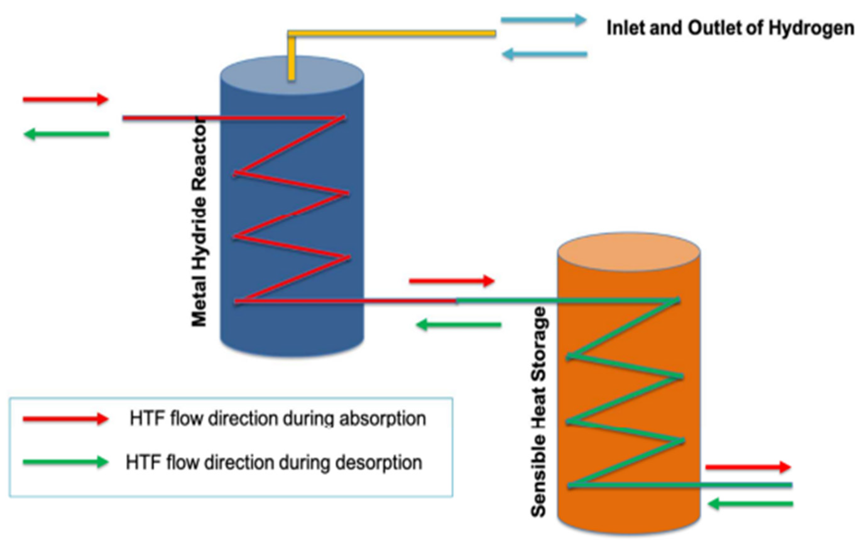
| Sensible | LaNi5 | Water | Helical tube embedded in both reactors | 20–97 | 4–20 (abs)/0.01–1.00 (des) | 2.5 kg powder/0.0375 kg H2 | Integration with thermocline storage achieved 81.7% storage efficiency during absorption and delivered 60% of required heat during desorption with over 70% discharging efficiency. | Numerical | 2023 | [246] |
| Latent | MgH2+4 at.-% Ti-V-Cr | Mg-Zn-Al Alloy | Cylindrical tank with internal heat exchanger | 300–360 | 10 (abs)/1 (des) | 10 kg material, 0.63 g H2 | The PCM effectively stored the heat of reaction during hydrogen absorption and provided it during desorption, resulting in a daily storage efficiency of 69%. | Experimental | 2013 | [241] |
| Latent | MgH2 | Mg69Zn28Al3 (at.-%) | Cylindrical, annular reactor with metal hydride bed in the core and the PCM surrounding the metal hydride in the annular gap | 300–370 | 8 (abs) | 10 kg material, 0.63 g H2 | A numerical model was proposed which agrees well with the experimental results of a MgH2 tank. It was shown that neglecting the natural convection in the fully melted PCM provides good results while simplifying the calculations. | Numerical | 2013 | [247] |
| Latent | MgH2 | Mg69Zn28Al3 (at.-%) | Metal hydride and PCM were separated by steel wall. | 300–360 | 10 (abs)/1 (des) | - | Two technical tank configurations were analyzed numerically. The spherical tank was found to have a higher system performance than a cylindrical tank. | Numerical | 2015 | [248] |
| Latent | Mg2Ni | NaNO3 | Cylindrical tubes filled with PCM concentrically inside the MH bed | 344 (abs)/270 (des) | 15 (abs)/2 (des) | - | Integration of PCM reduced filling time by 58.1%. Aluminum foam enhances thermal conductivity, reducing charging/discharging times. | Numerical | 2016 | [249] |
| Latent | LaNi5 | LiNO3–3 H2O | Heat exchange through steel wall between metal hydride tank and PCM. The PCM is located in four cylindrical tubes within the LaNi5 hydride bed. | 20–70 | 10 (abs)/1 (des) | 0.309 kg of LaNi5 alloy~0.004 kg H2 (est.) | Up to 80% of the hydrogen can be released utilizing the heat from the PCM. | Numerical | 2016 | [250] |
| Latent | LaNi5 | Paraffin RT35 | Heat exchange through steel wall between metal hydride tank and PCM. | 20–70 | 8 (abs) | 0.270 kg powder/~0.004 kg H2 (est.) | The influence of thermal conductivity, the mass and latent heat of the PCM on the system performance was studied. The high thermal conductivity of the PCM is beneficial to achieve a high capacity of the metal hydride storage system. The incorporation of metal foams further improves the system performance, with copper foam showing better performance than aluminum foam. | Numerical | 2019 | [251] |
| Latent | Mg2Ni | NaNO3 | Cylindrical sandwich bed packed with PCM | 307 | 12 (abs)/3 (des) | - | A new MH-PCM configuration reduced the time for hydrogenation by 81.5% and dehydrogenation by 73% compared to conventional systems. | Numerical | 2020 | [242] |
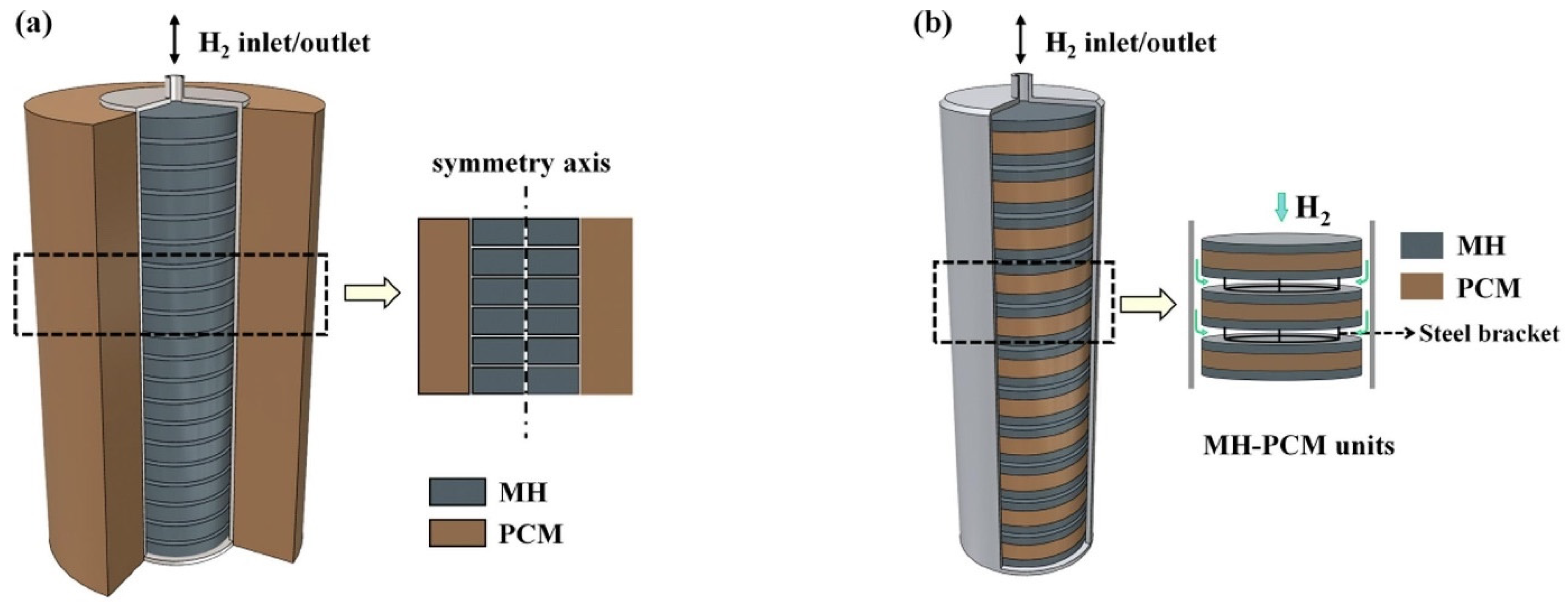
| Latent | MgH2 | NaNO3 | Two reactor configurations: 1. Annular reactor with MgH2 in the central part and the PCM located in the annular gap. Heat exchange through the steel wall. 2. Sandwiched MH-PCM units with steel brackets separating the units. | 280–372 | 10 (abs)/1 bar (des) | - | The configuration of the PCM affects the heat transfer. The sandwiched configuration exhibits improved performances. Absorption and desorption times are 78% and 59% shorter, respectively, for the sandwiched configuration. | Numerical | 2021 | [252] |
| Latent | LaNi5 | LiNO3·3 H2O | The application of metal foam was investigated. PCM channels within the metal hydride bed were investigated. | 20–70 | 10 (abs)/1 (des) | 0.4813 kg of alloy; ~0.006 kg H2 (est.) | PCM channels within hydride bed show superior performance compared to alternative structures of MH-PCM contacting. | Numerical | 2021 | [253] |
| Latent | MmNiMnCo (AB5 alloy) | RT35HC (Organic PCM) | Integrated PCM unit for MH thermal management | 35–40 | 10 (abs)/3 (des) | - | PCM-based thermal storage system captured heat released during hydrogen absorption and utilized it during hydrogen desorption, improving overall system efficiency. | Numerical | 2022 | [254] |
| Latent | MmNiMnCo (AB5 alloy) | RT35HC (Organic PCM) | Integrated PCM unit for MH thermal management | 35–40 | 10 (abs)/3 (des) | 0.072 kg | With the introduction of the PCM, hydrogen flows could be maintained significantly longer than without the PCM. Mixing Cu foam significantly enhanced the H2 charge and discharge performance. | Experimental | 2022 | [255] |
| Latent | LaNi5 | Paraffin + Metal Foams (Cu, Al, Ni, Ti) | Tube-and-shell heat exchanger | 22–56 | 50 (abs) | - | Metal foams enhance PCM thermal conductivity and melting rate. The Cu-metal foam showed the best thermal performance. Economic analysis pointed out as necessary to choose best metal foam. | Numerical | 2022 | [256] |
| Latent | LaNi5 | Paraffin C13-C24 pure and with 5 wt.% metal oxide (Al2O3, MgO, SiO2, SnO2) nanoparticle additives | Heat exchange through steel wall between metal hydride tank and PCM. The PCM is located in four cylindrical tubes within the LaNi5 hydride bed. | 20–60 | 50 (abs) | - | Mixing metal oxide nanoparticles with PCM was studied on a large-scale metal hydride storage reactor system. No effect was found of including 5 wt.% metal oxide additives on the overall thermal and hydrogen storage performance of the reactor. | Numerical | 2022 | [257] |
| Latent | LaNi5 | Paraffin RT35 | Heat exchange through steel wall between metal hydride tank and PCM. The PCM is located in four cylindrical tubes within the LaNi5 hydride bed. | 20–70 | 6–12 (abs) | - | Natural convection in the PCM increases the average hydrogen storage by 13%. Optimizing the thermal conductivity of the PCM is important to increase the system thermal performance. Higher inlet pressure improves storage rate but increases compression costs. Optimal inlet pressure for the system found to be approximately 10 bar. | Numerical | 2024 | [258] |
| Latent | Mg2FeH6/LaNi5 | C2H3O2Na·3 H2O | Heat exchange between the LaNi5 LTMH bed and the coupled PCM outer jacket occurs through the LTMH tank wall. | 46.85–61.85 | 5.6–9.7 (abs and des) | 0.0499 kg H2 | The proposed system couples Mg2FeH6 as a heat storage medium receiving waste heat and providing H2 to the low-temperature MH (LaNi5), which is coupled with a latent TES for thermal management. The temperature rise in the LaNi5 powder bed during H2 absorption is more pronounced at the center of the tank. Due to the melting of the PCM, its temperature rise is smaller than the one experienced by the MH powder bed itself. Desorption of H2 occurs faster at the MH/PCM interface. Heat is absorbed faster by the PCM in the form of latent heat, than sensible heat. Authors reported an efficiency of around 87% for the proposed system. | Numerical | 2024 | [259] |
| Thermochemical | MgH2 + 5 wt.% expanded natural graphite (ENG) | Mg(OH)2 + ENG (Pellet, block and powder + Al foam) | Integrated thermochemical storage | 305–370 | 10 (abs)/2 (des) | - | The system reduces the mass of the heat storage media by a factor of 4 compared to PCM-based systems. Offers flexibility in operating pressure conditions, enabling shorter hydrogen absorption times. | Numerical | 2016 | Bhouri et al. [260] |
| Thermochemical | MgH2 | Mg(OH)2/MgO | Adiabatic storage reactor | 280–330 | 1 (des) | - | Mg/MgH2–MgO/Mg(OH)2 system investigated numerically. Feasibility of H2-desorption with MgO hydration in the system demonstrated. Compatible reaction times were identified. | Numerical | 2019 | Lutz et al. [210] |
| Thermochemical | Mg90Ni10 | Mg(OH)2/MgO | Adiabatic storage reactor | 370 (abs)/300 (des) | 9 (abs)/1 (des) | 0.012 kg H2 | Absorption under 9 bar H2 and 60 mbar H2O; H2 release and CaO hydration at 10 bar H2O and 300 °C demonstrated. High volumetric capacity at low pressures. | Numerical and Experimental | 2020 | Lutz et al. [261] |
| Thermochemical | LaNi5 | Na2HPO3·7 H2O | Metal hydride contained in a steel tank surrounded by PCM directly. | 20–70 | 6–10 (abs) | 0.078 kg powder; ~0.001 kg H2 (est.) | A 3D model of a metal hydride reactor with PCM was presented. The effects of operating pressure and PCM properties were investigated. A higher operating pressure is beneficial in achieving a higher reaction fraction, e.g., the reacted fraction at 2400 s increases from 53% at 6 bar to 77% at 10 bar. Reported metal hydride reactor gravimetric capacity of 0.58 wt.%. Electrical power of FC coupled system 8.2 kJ. | Numerical and Experimental | 2020 | Yao et al. [262] |
| Thermochemical | MgH2 | Mg(OH)2/MgO | A heat exchanger with fins was modeled. The heat exchanger fins were optimized as part of the study. | 300–370 | 10 (abs) | - | The heat of reaction of the Mg/MgH2 system is stored using the thermochemical dehydrogenation of Mg(OH)2. Through topology optimization of the heat exchanger and the metal hydride and TES material, the charging performance can be improved. | Numerical | 2022 | Shi et al. [263] |
| Thermochemical | MgH2 | Mg(OH)2/MgO | No HT fluid, TCS material around MH | 300–360 | 10 (abs) | - | Absorption takes place at 10 bar and desorption is studied at 5 bar backpressures. The thermal management can be optimized by adjusting the water vapor pressure. An increase in water pressure decreases the dehydrogenation time of the MgH2 material. | Numerical | 2022 | Shi et al. [264] |
| Thermochemical | LaNi5 | LiNO3·3 H2O | Double-walled cylinder with MH/PCM (no thermal losses) | 20–120 | 6 (abs)/0.068 (des) | 0.0324 kg H2 | Development of a non-dimensional methodology to identify MH-PCM/TCS materials pairings based on charge/discharge and equivalent power. | Numerical | 2024 | Maggini et al. [265] |
Disclaimer/Publisher’s Note: The statements, opinions and data contained in all publications are solely those of the individual author(s) and contributor(s) and not of MDPI and/or the editor(s). MDPI and/or the editor(s) disclaim responsibility for any injury to people or property resulting from any ideas, methods, instructions or products referred to in the content. |
© 2024 by the authors. Licensee MDPI, Basel, Switzerland. This article is an open access article distributed under the terms and conditions of the Creative Commons Attribution (CC BY) license (https://creativecommons.org/licenses/by/4.0/).
Share and Cite
Davis Cortina, M.; Romero de Terreros Aramburu, M.; Neves, A.M.; Hurtado, L.; Jepsen, J.; Ulmer, U. The Integration of Thermal Energy Storage Within Metal Hydride Systems: A Comprehensive Review. Inorganics 2024, 12, 313. https://doi.org/10.3390/inorganics12120313
Davis Cortina M, Romero de Terreros Aramburu M, Neves AM, Hurtado L, Jepsen J, Ulmer U. The Integration of Thermal Energy Storage Within Metal Hydride Systems: A Comprehensive Review. Inorganics. 2024; 12(12):313. https://doi.org/10.3390/inorganics12120313
Chicago/Turabian StyleDavis Cortina, Matias, Manuel Romero de Terreros Aramburu, Andre Martins Neves, Lourdes Hurtado, Julian Jepsen, and Ulrich Ulmer. 2024. "The Integration of Thermal Energy Storage Within Metal Hydride Systems: A Comprehensive Review" Inorganics 12, no. 12: 313. https://doi.org/10.3390/inorganics12120313
APA StyleDavis Cortina, M., Romero de Terreros Aramburu, M., Neves, A. M., Hurtado, L., Jepsen, J., & Ulmer, U. (2024). The Integration of Thermal Energy Storage Within Metal Hydride Systems: A Comprehensive Review. Inorganics, 12(12), 313. https://doi.org/10.3390/inorganics12120313