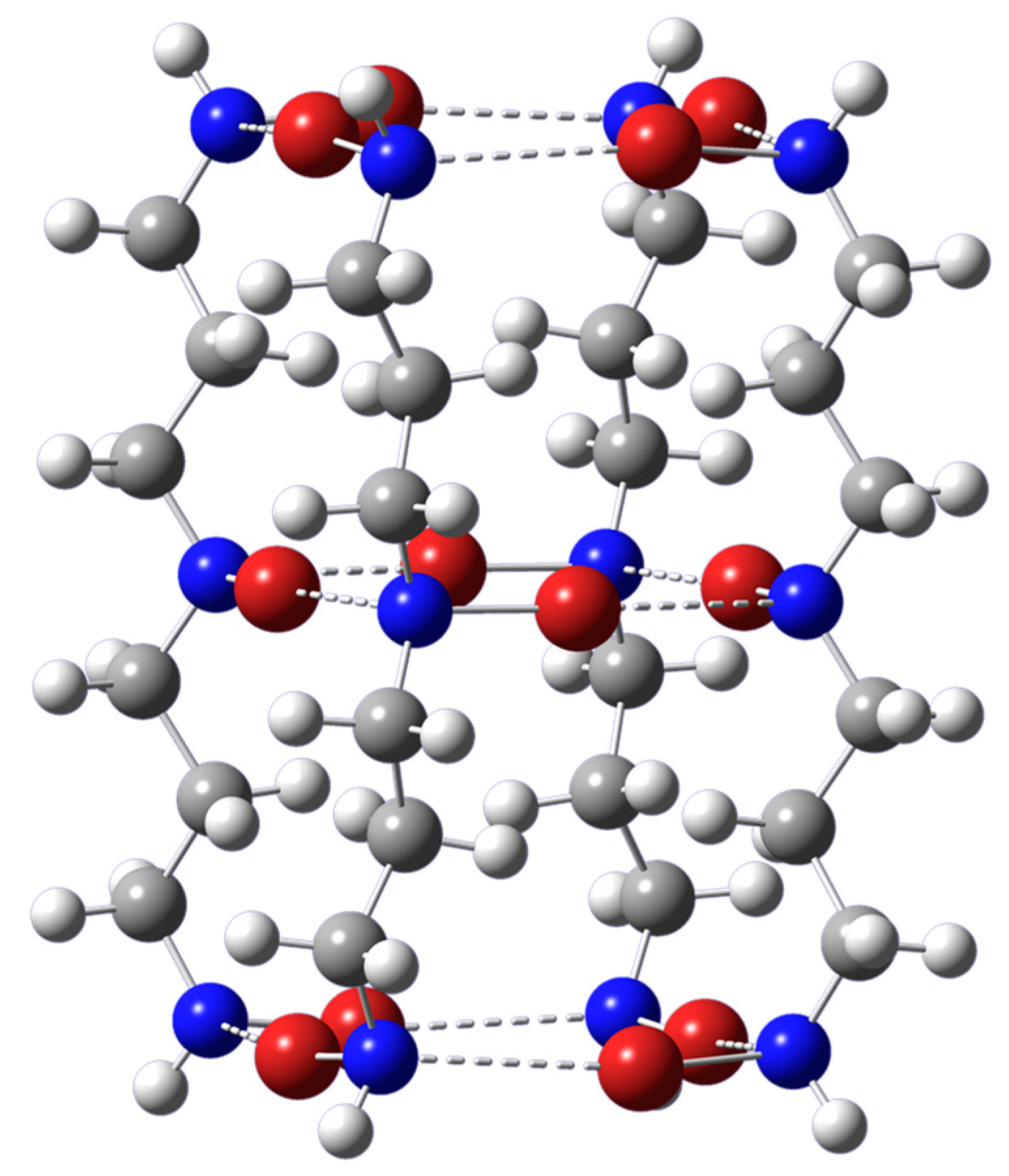
Figure 1.
Optimized geometry of the [NHX-(CH2)3-NX-(CH2)3-NHX]4 self-assembled tube-like structure with C4h symmetry. Dashed lines represent N-X···N halogen bonds. The color representation is as follows: white (H), gray (C), blue (N), and red (Br). Shown are the results for X = Br. The optimized geometries for X = Cl or I essentially look the same.
Figure 2.
Optimized geometry of the intramolecular tube-like structure based on the intermolecular [NHX-(CH2)3-NX-(CH2)3-NHX]4 self-assembled structure. Dashed lines represent N-X···N halogen bonds. The color representation is as follows: white (H), gray (C), blue (N), red (Br), and green (Si). Shown are the results for X = Br. The optimized geometries for X = Cl or I essentially look the same.
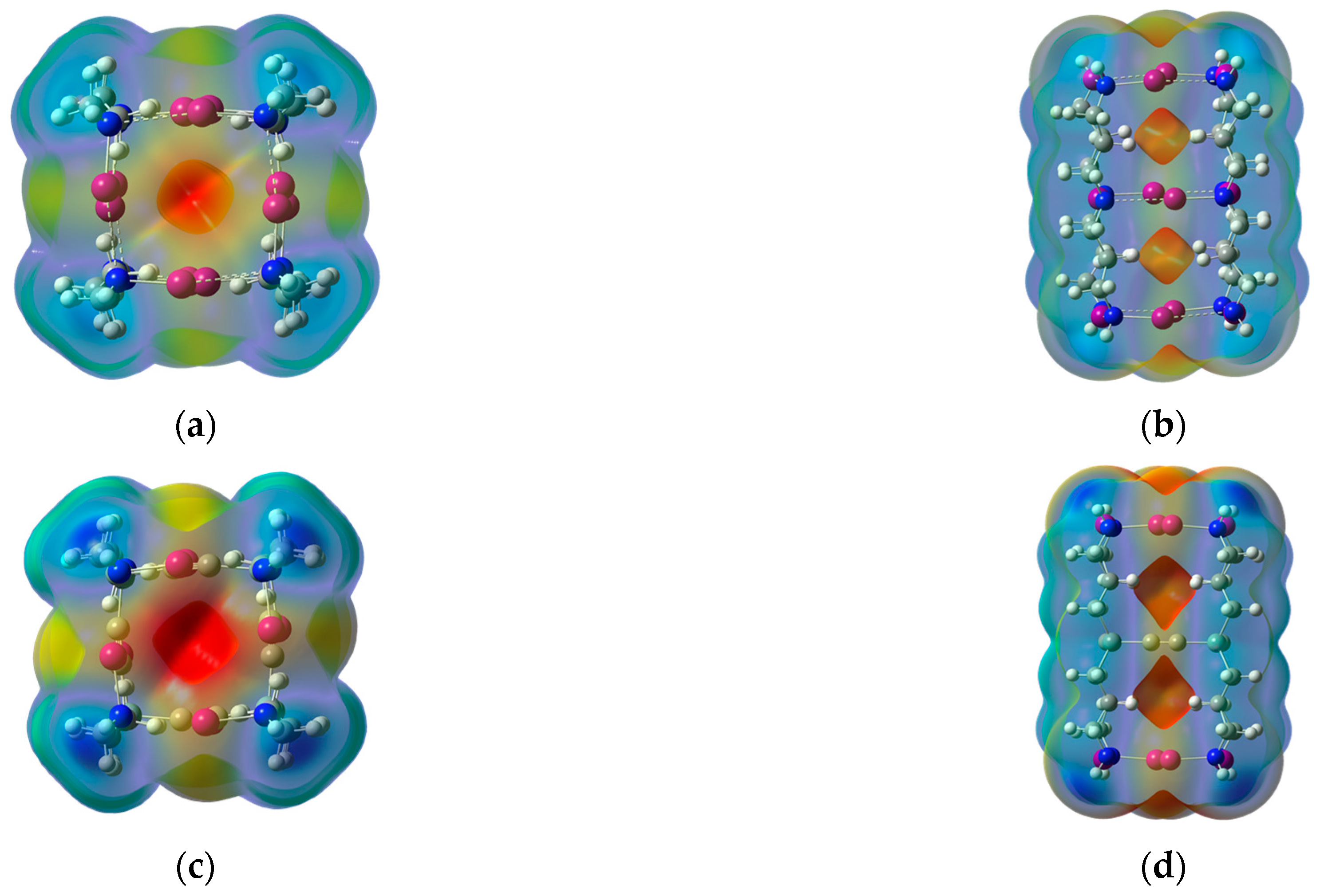
Figure 3.
Top views and side views of the ωB97XD/DGDZVP molecular electrostatic potential at the 0.001 au molecular surface of the intermolecular tube-like structures shown in the upper panel, (a,b). The corresponding intramolecular structures are shown in the lower panel, (c,d). Red areas represent the most negative potential and blue areas the most positive ones. The results shown are for X = I. Similar results are obtained for X = Cl or Br.
Figure 4.
Optimized geometries of the terminal (a) and central (b) Li+ complexes with the tetrameric tube-like host structure. Dashed lines represent N-X···N halogen bonds and Li+···X binding interactions. The color representation is as follows: white (H), gray (C), blue (N), red (Br), and green (Si). Shown are the results for X = Br. The optimized geometries for X = Cl or I essentially look the same.
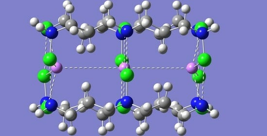
Figure 5.
Optimized geometries of the terminal (a) and central (b) Li+ complexes with the intramolecular tube-like host structure. Dashed lines represent N-X···N halogen bonds and Li+···X binding interactions. The color representation is as follows: white (H), gray (C), blue (N), red (Br), pink (Li+), and green (Si). Shown are the results for X = Br. The optimized geometries for X = Cl or I essentially look the same.
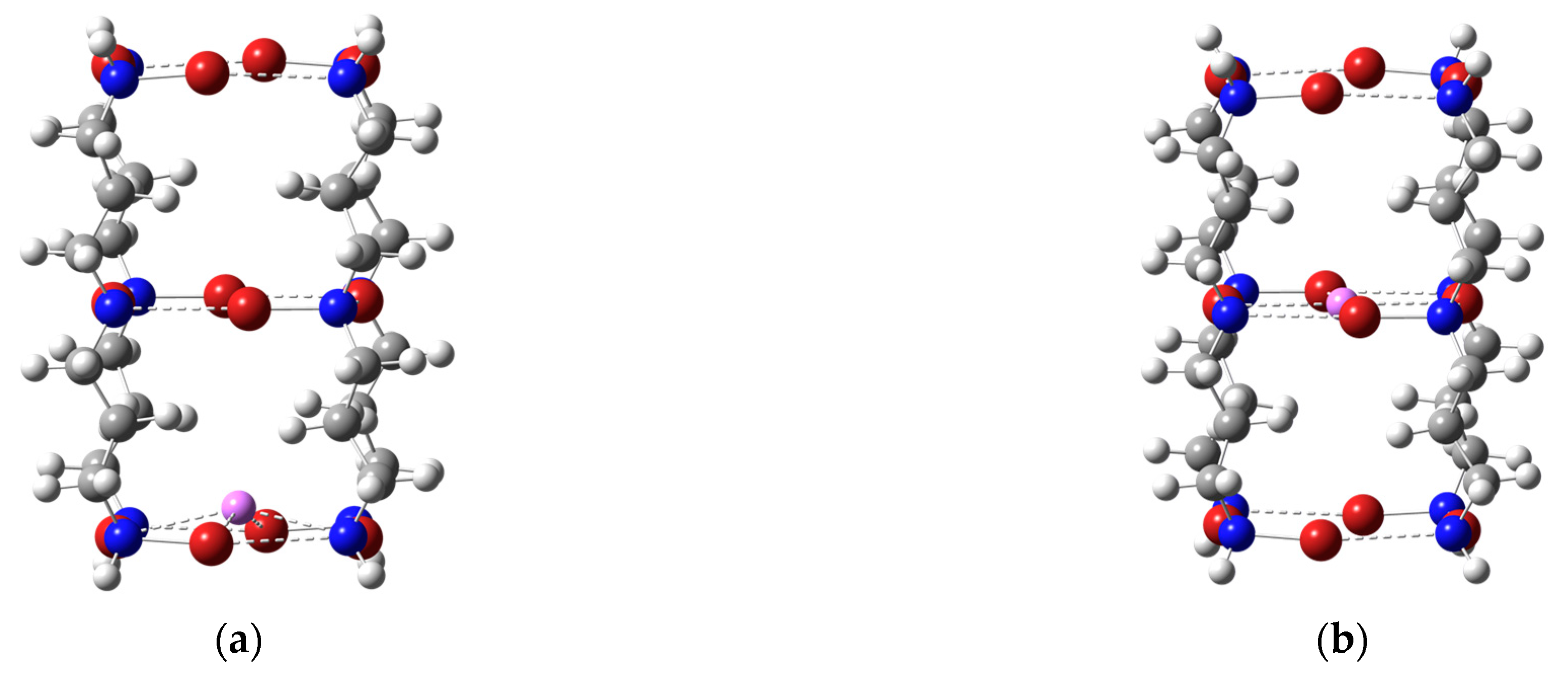
Figure 6.
Optimized geometries of the transition-state structures connecting the two Li+ complexes (terminal and central) with the tetrameric host (a) and intramolecular host (b). Dashed lines represent N-X···N halogen bonds. The color representation is as follows: white (H), gray (C), blue (N), red (Br), pink (Li+), and green (Si). Shown are the results for X = Br. The related optimized geometries for X = Cl or I essentially look the same.
Figure 7.
Relative electronic energy, Erel, along the intrinsic reaction coordinate (IRC), connecting the terminal and central complexes for the Li+ complexes with the [NHX-(CH2)3-NX-(CH2)3-NHX]4 hosts. Shown are the results for when X = Br.
Figure 7.
Relative electronic energy, Erel, along the intrinsic reaction coordinate (IRC), connecting the terminal and central complexes for the Li+ complexes with the [NHX-(CH2)3-NX-(CH2)3-NHX]4 hosts. Shown are the results for when X = Br.
Figure 8.
Relative electronic energy, Erel, along the intrinsic reaction coordinate (IRC), connecting the terminal and central complexes for the Li+ complexes with the intramolecular host for when X = Cl.
Figure 8.
Relative electronic energy, Erel, along the intrinsic reaction coordinate (IRC), connecting the terminal and central complexes for the Li+ complexes with the intramolecular host for when X = Cl.
Table 1.
BSSE-corrected interaction energies, ∆E, and corresponding average values, averaged over 12 such interactions present, <∆E>, for the formation of the tetrameric halogen-bonded structures. Energy values in kcal/mol.
Table 1.
BSSE-corrected interaction energies, ∆E, and corresponding average values, averaged over 12 such interactions present, <∆E>, for the formation of the tetrameric halogen-bonded structures. Energy values in kcal/mol.
| X | ∆E | <∆E> |
|---|
| Cl | −24.87 | −2.07 |
| Br | −50.13 | −4.18 |
| I | −74.10 | −6.18 |
Table 2.
Halogen-bond distances (Å) and angles (degrees) for the optimized intermolecular halogen-bonded tetramers. Also listed are the distance between opposing or adjacent halogen atoms, X = Cl, Br, or I, in the corresponding terminal or central halogen-bonded network. Values for the terminal halogen bonds in the tubular structure are listed first, followed by those of the central halogen bonds.
| | Distances |
| | Cl | Br | I |
| X···N | 3.058 | 3.036 | 3.085 |
| X···X a | 5.329 | 5.440 | 5.710 |
| X···X b | 3.768 | 3.847 | 4.038 |
| X···N | 2.943 | 2.934 | 3.023 |
| X···X a | 5.268 | 5.359 | 5.663 |
| X···X b | 3.725 | 3.790 | 4.005 |
| | Angles |
| | Cl | Br | I |
| N-X···N | 168.0 | 167.9 | 168.5 |
| N-X···N | 168.2 | 169.4 | 171.7 |
Table 3.
Second-order delocalization energies, <E2> (kcal/mol), and electron density at halogen bond critical point, ρc (a.u.), in the intermolecular halogen-bonded tetramers. Values for the terminal halogen bonds in the tubular structure are listed first, followed by those of the central halogen bonds.
| | ρc |
| | Cl | Br | I |
| X···N | 0.0119 | 0.0144 | 0.0171 |
| X···N | 0.0152 | 0.0179 | 0.0195 |
| | <E2> |
| | Cl | Br | I |
| N-X···N | 2.51 | 4.69 | 7.48 |
| N-X···N | 3.25 | 5.97 | 8.57 |
Table 4.
Halogen-bond distances (Å) and angles (degrees) for the optimized halogen bonds in the intramolecular halogen-bonded network model system. Also listed are the distance between opposing and adjacent halogen atoms, X = Cl, Br, or I, in the corresponding halogen-bonded network.
Table 4.
Halogen-bond distances (Å) and angles (degrees) for the optimized halogen bonds in the intramolecular halogen-bonded network model system. Also listed are the distance between opposing and adjacent halogen atoms, X = Cl, Br, or I, in the corresponding halogen-bonded network.
| | Distances |
| | Cl | Br | I |
| X···N | 3.038 | 2.967 | 2.974 |
| X···X a | 5.300 | 5.362 | 5.604 |
| X···X b | 3.748 | 3.792 | 3.963 |
| | Angles |
| | Cl | Br | I |
| N-X···N | 169.4 | 168.9 | 166.9 |
Table 5.
Second-order delocalization energies, <E2> (kcal/mol), and electron density at halogen bond critical point, ρc (a.u.), in the intramolecular tubular halogen-bonded networks.
Table 5.
Second-order delocalization energies, <E2> (kcal/mol), and electron density at halogen bond critical point, ρc (a.u.), in the intramolecular tubular halogen-bonded networks.
| | Cl | Br | I |
|---|
| ρc | 0.0123 | 0.0164 | 0.0209 |
| <E2> | 2.71 | 5.82 | 10.23 |
Table 6.
BSSE-corrected complexation energies, ∆E, for both the terminal and central Li+ complexes with the X-bonded intermolecular networks. Energy values in kcal/mol.
Table 6.
BSSE-corrected complexation energies, ∆E, for both the terminal and central Li+ complexes with the X-bonded intermolecular networks. Energy values in kcal/mol.
| X | Terminal Complex | Central Complex |
|---|
| Cl | −80.61 | −84.41 |
| Br | −78.61 | −81.62 |
| I | −75.84 | −77.86 |
Table 7.
Relevant distances (Å) and angles (degrees) for the optimized Li+ terminal complex with the intermolecular halogen-bonded tetramers. Values for the terminal end of the tubular structure that binds Li+ are listed first, followed by those of the central halogen bonds and then by those at the other end of the tube.
| | Distances |
| | Cl | Br | I |
| X···N | 2.928 | 2.959 | 3.020 |
| X···N | 2.959 | 2.954 | 3.048 |
| X···N | 3.046 | 3.019 | 3.076 |
| X···Li+ | 2.630 | 2.772 | 3.005 |
| | Angles |
| | Cl | Br | I |
| N-X···N | 168.2 | 167.4 | 167.1 |
| N-X···N | 168.6 | 169.8 | 169.8 |
| N-X···N | 168.2 | 168.1 | 167.6 |
| X···Li+···X | 161.0 | 153.2 | 141.6 |
Table 8.
Relevant distances (Å) and angles (degrees) for the optimized Li+ central complex with the intermolecular halogen-bonded tetramers. Values for the terminal end of the tubular structure are listed first, followed by those of the central part that binds Li+ and then by those at the other end of the tube.
| | Distances |
| | Cl | Br | I |
| X···N | 3.027 | 3.010 | 3.064 |
| X···N | 2.902 | 2.952 | 3.057 |
| X···N | 3.027 | 3.010 | 3.072 |
| X···Li+ | 2.604 | 2.722 | 2.935 |
| | Angles |
| | Cl | Br | I |
| N-X···N | 168.1 | 168.3 | 167.9 |
| N-X···N | 169.0 | 167.9 | 167.8 |
| N-X···N | 168.1 | 168.3 | 167.7 |
| X···Li+···X | 180.0 | 180.0 | 158.7 |
Table 9.
Second-order delocalization energies, <E2> (kcal/mol), and electron density at halogen bond critical point, ρc (a.u.), in the Li+ central and terminal complexes. Also listed are the corresponding values for the N-X···Li+ interactions. Values for the terminal halogen bonds are listed first, followed by those of the central halogen bonds and then by those at the other end of the tube.
| | Terminal Complex | Central Complex |
| | ρc | ρc |
| | Cl | Br | I | Cl | Br | I |
| N-X···N | 0.0156 | 0.0170 | 0.0194 | 0.0126 | 0.0151 | 0.0177 |
| N-X···N | 0.0148 | 0.0172 | 0.0187 | 0.0168 | 0.0177 | 0.0186 |
| N-X···N | 0.0121 | 0.0149 | 0.0173 | 0.0126 | 0.0151 | 0.0174 |
| N-X···Li+ | 0.0086 | 0.0084 | 0.0078 | 0.0091 | 0.0092 | 0.0088 |
| | Terminal Complex | Central Complex |
| | <E2> | <E2> |
| | Cl | Br | I | Cl | Br | I |
| N-X···N | 3.89 | 5.98 | 9.05 | 2.77 | 5.10 | 8.03 |
| N-X···N | 3.14 | 5.70 | 8.09 | 3.91 | 5.69 | 7.65 |
| N-X···N | 2.61 | 4.95 | 7.71 | 2.77 | 5.10 | 7.82 |
| N-X···Li+ | 11.17 | 17.09 | 29.50 | 10.25 | 14.92 | 28.25 |
Table 10.
BSSE-corrected complexation energies, ∆E, for both the terminal and the central Li+ complexes with the X-bonded intramolecular networks. Energy values in kcal/mol.
Table 10.
BSSE-corrected complexation energies, ∆E, for both the terminal and the central Li+ complexes with the X-bonded intramolecular networks. Energy values in kcal/mol.
| X | Terminal Complex | Central Complex |
|---|
| Cl | −81.20 | −86.14 |
| Br | −78.74 | −85.33 |
| I | −75.02 | −83.90 |
Table 11.
Relevant distances (Å) and angles (degrees) for the optimized Li+ terminal complex with the intramolecular halogen-bonded host systems. Values for the terminal halogen-bonded network of the tubular structure that binds Li+ are listed first, followed by those of the halogen-bonded network at the other end of the tube and then the values pertaining to the Li+ binding interaction.
| | Distances |
| | Cl | Br | I |
| X···N | 2.911 | 2.924 | 2.958 |
| X···N | 3.021 | 2.952 | 2.964 |
| X···Li+ | 2.617 | 2.733 | 2.930 |
| | Angles |
| | Cl | Br | I |
| N-X···N | 169.0 | 167.3 | 165.4 |
| N-X···N | 169.6 | 168.9 | 166.8 |
| X···Li+···X | 163.4 | 159.3 | 149.4 |
Table 12.
Relevant distances (Å) and angles (degrees) for the optimized Li+ central complex with the intramolecular halogen-bonded host systems. Values for the terminal halogen-bonded networks are listed first, followed by those with respect to the midpoint of each C≡C bond in the silicon-linked alkyne network that binds the metal ion.
| | Distances |
| | Cl | Br | I |
| X···N | 2.995 | 2.934 | 2.956 |
| (C≡C)···Li+ | 2.599 | 2.599 | 2.601 |
| | Angles |
| | Cl | Br | I |
| N-X···N | 169.7 | 169.1 | 167.0 |
| (C≡C)···Li+···(C≡C) | 180.0 | 180.0 | 180.0 |
Table 13.
Second-order delocalization energies, <E2> (kcal/mol), and electron density at key bond critical points, ρc (a.u.), in the Li+ central and terminal complexes with the intramolecular host system. Values for the terminal halogen bonds binding Li+ are listed first.
Table 13.
Second-order delocalization energies, <E2> (kcal/mol), and electron density at key bond critical points, ρc (a.u.), in the Li+ central and terminal complexes with the intramolecular host system. Values for the terminal halogen bonds binding Li+ are listed first.
| | Terminal Complex |
| | ρc | <E2> |
| | Cl | Br | I | Cl | Br | I |
| N-X···N | 0.0161 | 0.0182 | 0.0218 | 4.14 | 6.65 | 10.62 |
| N-X···N | 0.0127 | 0.0169 | 0.0213 | 2.86 | 6.09 | 10.54 |
| N-X···Li+ | 0.0088 | 0.0091 | 0.0091 | 11.96 | 18.82 | 31.61 |
| | Central Complex |
| | ρc | <E2> |
| | Cl | Br | I | Cl | Br | I |
| N-X···N | 0.0134 | 0.0175 | 0.0215 | 3.11 | 6.44 | 10.81 |
| (C≡C)···Li+ | 0.0070 | 0.0070 | 0.0070 | 0.67 | 0.67 | 0.67 |
Table 14.
Electronic (Erel) and Gibbs (Grel) free energies of the terminal complex relative to the central complex of the Li+ complexes with the inter- and intramolecular hosts. Energy barriers to the transition from the terminal to central complex are indicated with a dagger symbol as superscript, Eǂ and Gǂ, respectively. All relative energies are in kcal/mol.
| | Intermolecular |
| | Erel | Grel | Eǂ | Gǂ |
| Cl | 3.81 | 4.02 | 12.84 | 11.70 |
| Br | 3.25 | 2.28 | 9.02 | 8.16 |
| I | 2.40 | 3.19 | 5.29 | 2.80 |
| | Intramolecular |
| | Erel | Grel | Eǂ | Gǂ |
| Cl | 1.40 | 3.48 | 14.14 | 13.94 |
| Br | 3.40 | 2.66 | 13.72 | 12.62 |
| I | 5.64 | 5.72 | 13.51 | 12.51 |
Table 15.
NBO charges (in a.u.) for lithium ion, qLi+, and the closest hydrogen atoms, qH, in the central, terminal, and transition state (TS) complexes of Li+ with the inter- and intra-molecular tube-like X-bonded hosts, X = Cl, Br, or I. Also listed are the distances (in Ǻ) between Li+ and the corresponding hydrogen atoms, Li+···H.
| | Intermolecular | Intramolecular |
| | Cl | Cl |
| | Central | TS | Terminal | Central | TS | Terminal |
| qLi+ | 0.89 | 0.87 | 0.91 | 0.93 | 0.91 | 0.91 |
| qH | 0.21 | 0.20 | 0.21 | 0.21 | 0.19 | 0.21 |
| Li+···H | 3.55 | 2.38 | 3.47 | 3.91 | 2.42 | 3.63 |
| | Br | Br |
| | Central | TS | Terminal | Central | TS | Terminal |
| qLi+ | 0.88 | 0.85 | 0.88 | 0.93 | 0.90 | 0.88 |
| qH | 0.21 | 0.21 | 0.21 | 0.21 | 0.20 | 0.21 |
| Li+···H | 3.65 | 2.47 | 3.46 | 3.94 | 2.48 | 3.62 |
| | I | I |
| | Central | TS | Terminal | Central | TS | Terminal |
| qLi+ | 0.82 | 0.77 | 0.81 | 0.93 | 0.86 | 0.82 |
| qH | 0.21 | 0.20 | 0.21 | 0.21 | 0.19 | 0.21 |
| Li+···H | 3.50 | 2.86 | 3.51 | 4.04 | 2.50 | 3.57 |


