Article

Metal Chelation Enables High-Performance Tea Polyphenol Electrodes for Lithium-Ion Batteries

1
Guangdong-Hong Kong-Macau Joint Laboratory for Photonic-Thermal-Electrical Energy Materials and Devices, Institute of Applied Physics and Materials Engineering, University of Macau, Avenida da Universidade, Taipa, Macau SAR 999078, China
2
The State Key Laboratory of Refractories and Metallurgy, Wuhan University of Science and Technology, Wuhan 430081, China
3
School of Materials and Physics, China University of Mining and Technology, Xuzhou 221116, China
*
Author to whom correspondence should be addressed.
These authors contributed equally to this work.
Inorganics 2023, 11(4), 148; https://doi.org/10.3390/inorganics11040148
Submission received: 24 February 2023 / Revised: 23 March 2023 / Accepted: 29 March 2023 / Published: 31 March 2023

Abstract

:
The application of organic electrode materials can make the whole cycle of the lithium battery operation effective for green sustainability. However, poor electronic conductivity and strong solubility in nonprotonic electrolytes limit the application of organic anodes. Here, a novel organic anode material, TP-Ni, was fabricated through the simple chelation of tea polyphenols with nickel ions. Benefiting from coordination bonds that alter the intrinsic microstructure of TPs and contribute to pseudocapacitive charging, the TP-Ni anode exhibits remarkable electrochemical properties, including a high specific capacity (1163 mAh g−1 at 0.1 A g−1), superb rate capability, and extraordinary cycling stability (5.0 A g−1 over 4000 cycles with a capacity retention of 87.8%). This work can provide guidance for the design and synthesis of new high-performance organic electrode materials in the future and help accelerate the process of organic electrode material applications.

Graphical Abstract

1. Introduction

The increasing awareness of environmental protection has driven the development of clean and efficient energy sources, particularly lithium-ion batteries (LIBs) [1,2,3]. Additionally, the research on anode material, which is one of the factors determining the electrochemical performance of LIBs, has gone through a long process. Initially, lithium metal was widely studied for its impressively high specific capacity of 3860 mAh g−1 and low voltage [4]. Unfortunately, its potential for practical use was limited by the growth of lithium dendrites during continuous charging and discharging, which triggered severe capacity degradation and serious safety hazards [5]. Currently, graphite is the most commonly utilized anode material in commercially available LIBs, featuring good electrical conductivity, low working potential, and a strong laminar structure. These properties allow for the better embedding and detachment of lithium ions (Li+) during charging and discharging, achieving good cycling performance [6,7]. Nevertheless, the reaction of graphite with up to six lithium ions (forming LiC6 in the lithium-rich state) leads to a lower theoretical specific capacity of 372 mAh g−1 and a lower practical energy density, with limited possibilities for improvement [8]. In addition, the lower diffusion rate of lithium ions in graphite-based materials leads to the unsatisfactory power density of the battery, while metal oxides such as lithium cobaltate and lithium iron phosphate with actual specific capacities of 140~170 mAh g−1 suffer from a significant volume expansion effect, thereby not meeting the criteria for the structural stability, energy density, and service life of large-scale energy systems [9]. Most importantly, all of the aforementioned anode materials are non-renewable and bring about problems such as resource shortage and environmental pollution, which are also a cause for concern [10]. Therefore, it is essential to develop a novel anode material that possesses desirable electrochemical properties, such as a high specific capacity, excellent rate capability, and long cycle stability, to fulfill the requirements of next-generation “green” LIBs [11].
As an alternative to inorganic compounds, electroactive organic compounds that can perform reversible redox reactions have been proposed as the new generation of environmentally friendly LIBs, which are safe, clean, affordable, and reusable [12]. Organic compounds do not involve expensive elements and do not require high-temperature annealing during preparation, with lower CO2 emissions than inorganic compounds [13]. More critically, most organic materials can be extracted directly from natural plants or be processed by organic synthesis methods, making the whole operational cycle of LIBs truly and effectively sustainable [14,15,16,17]. However, most organic cells are constrained by their inherent insulating properties and high solubility in the electrolyte [18], resulting in the low utilization of the active material, such as carbonyl compounds [19,20], conductive polymers [21,22], and free radical compounds [23,24]. Apart from their physical or chemical instability, the microstructure and particle dimensions also affect the electrochemical behavior of organic anodes since dissolved Li+ is transported more rapidly in smaller, non-crystalline particles [25]. Many reported experiments were conducted at low charge and discharge currents, making the practical use of high-performance LIBs a significant challenge [24,26]. Therefore, it is imperative to find new organic compounds that support high current charge/discharge operations with good cycling stability and an impressive rate capability to deploy organic LIBs for electric vehicles and energy storage systems.
In this study, biodegradable tea polyphenols (TPs) were chelated with nickel ions as an anode material, TP-Ni, for LIBs. Due to the robust coordination of divalent nickel ions with catechol groups, the microstructure of TP was substantially altered. This modification led to a significant increase in Li+ diffusion coefficients and pseudocapacitive storage capacity, enabling extraordinary overall electrochemical properties, including an exceptional energy density, superb cycling stability, and terrific rate performance. This work sheds light on the design and synthesis of new high-performance organic electrode materials for advanced LIBs.

2. Results and Discussion

As shown in Figure S1, the compound TP-Ni was synthesized by coordinating catechol groups with nickel ions in a ratio of 1:3. The strong interaction allows the complex to separate from the solution and precipitate out, and the precipitate can be easily isolated by filtration or centrifugation. Most previously reported organic electrode materials involve harmful reactants, high energy consumption, and harsh reaction conditions. In contrast, the entire preparation process in this work does not require high temperatures or cause any environmental damage, which is aligned with the sustainable development goals. More importantly, TP-Ni is quite stable in the electrolyte due to the strong chelating effect, while pristine TP is soluble in the electrolyte (Figure S2), which enhances the battery’s properties.
Scanning electron microscopy (SEM) was used to investigate the morphology of TP and TP-Ni samples. Figure 1a shows that TP consists of flaky particles with an irregular shape, and after the chelating reaction, the particle size became smaller (Figure 1b,c). This phenomenon may be caused by the close interaction between catechol groups and nickel ions that directly makes the TP molecules nanosized, thus altering the relative stability of the physical phase and facilitating the rate performance of the electrode material [27]. The XRD pattern shows a diffraction peak of the TP material at 23° (Figure S3), which becomes broader after the introduction of nickel ions. These results indicate that the coordination strategy can reduce the size of TP and transform it into a more amorphous structure. EDS detected a nickel content of 4.02 wt.% (Table S1), which is slightly lower than the theoretically predicted value of 5.32 wt.% based on the mass feed ratio, likely due to the non-uniformity of the nickel distribution throughout the probed depth [28]. The thermogravimetric analysis (TGA) results in Figure 1h also suggest that TP-Ni exhibits superior thermal stability compared to TP.
As the Fourier transform infrared spectroscopy (FTIR) results show (Figure 1i), the broad peak near 571 cm−1 indicates the stretching mode of the Ni–O bond, which is also reported in the literature [29,30]. After chelation with the nickel ion, the sharp peak at 1692 cm−1 attributed to the C=O stretching vibration becomes weak, indicating that catechol and a metal ion undergo a coordination reaction [31]. Additionally, the characteristic peak (1373 cm−1) of the catechol group is red-shifted to 1366 cm−1, further implying that the catechol group is the binding site for nickel ions [32]. The aromatic C=C stretching (1612 cm−1), ring stretching (1517 cm−1), C–H stretching of methylene on aromatic rings (1460 cm−1), and phenolic C–O–H stretching (1240 cm−1) [33] shift to lower wavenumbers owing to the breakage of hydrogen bonds that promote metal chelation [34]. Hydroxyl group bands were observed within the region of 3500 to 3200 cm−1 in TP and TP-Ni, suggesting that there is no significant influence on the phenol hydroxyl group after coordination [35]. The formation of metal complexes affects the electronic charge distribution throughout the molecule, as evidenced by the decrease in the wavenumber of the aromatic ring vibrations and the appearance of complex bands in the spectra of the ν (C–O) of the catechol groups involved in metal chelation. The presence of nickel ions in TP-Ni was confirmed by X-ray photoelectron spectroscopy (XPS), as shown in Figure 1j. As shown in Figure S4, there is no noticeable change in the valence state of Ni, as the shake-up peak in the Ni 2p region is diagnostic for the Ni2+ octahedral complex. An observed increase in binding energy is attributed to the ligands changing to more effective donor atoms [36,37]. In addition, the spectra of C1s and O1s show a shift of C=O and C–O to lower binding energies, indicating that the binding of nickel to oxygen atoms increases the electron density of both the oxygen atoms and the carbon atoms bound to oxygen. In addition, the peaks indicative of the catechol-Ni complex at 501 and 654 cm−1 can be observed in the Raman spectra in Figure S5, confirming the presence of robust coordination. The stretching vibrations of the C=O group coupled with the in-plane deformation of C–H and C–OH in the benzene ring (1567 cm−1) and C–O stretching (1365 cm−1) are both shifted down in the Raman spectrum, indicating that the catechol oxygen atom is deprotonated and coordinated to the nickel ion [38]. In the low-wavelength region, the band changes between 550 and 850 cm−1 are associated with the deformation of the benzene ring induced by the chelation of the catechol group [39].
The electrochemical properties of the TP-Ni sample were characterized with CR2032-type half-cells assembled in the Ar glove box with both humidity and oxygen contents < 1 ppm. The first three cyclic voltammogram (CV) curves of the TP-Ni anode are shown in Figure 2a. During the initial discharge, a small peak appears at 1.0 V and disappears in the following cycles due to the irreversible reactions of residual phenol groups with dissolved Li+. Another broadened peak at 0.4 V is attributed to the formation of the solid electrolyte interface (SEI), which disappears in the continuous cycles. During the charging process, a clearly broadened peak at 1.3 V is observed and is present in the following CV curves, indicating the outstanding lithiation/delithiation capability of TP-Ni. The two subsequent CV curves have almost the same shape, demonstrating the excellent reversibility of TP-Ni during the charge/discharge cycle. As seen in the Nyquist plots (Figure S6), the semicircle is attributed to the charge-transfer resistance associated with the interfacial transfer of lithium ions, while the steep line is attributed to the diffusion of lithium-lithium ions into the active material [40,41]. The results showed that TP-Ni had a lower charge-transfer resistance and a higher lithium-ion diffusion coefficient than TP (Table S2), which can be attributed to the nanosizing process, which shortened the diffusion paths and increased the area of contact between the electrode material and the electrolytes.
In Figure 2b, the initial discharge capacity of the TP-Ni anode is 1163 mAh g−1, and the reversible charging capacity reaches 713 mAh g−1 with an initial coulomb efficiency (ICE) [42] of 61.3%, which exceeds the value of most reported organic anodes [43,44]. This capacity loss is caused by the evolution of the SEI and side reactions. In the following cycles, TP−Ni provides reversible specific capacities of up to 836 mAh g−1, far beyond those of commercial LIBs. On the contrary, the pristine TP provides a discharge capacity of only 545 mAh g−1 during the first cycle, and worse, it drops quickly to 382 mAh g−1 in the subsequent cycle (Figure S7). The increase in high capacity observed from TP to TP-Ni can be ascribed to the powerful coordination interaction, which changes the intrinsic morphology of TP to a more amorphous structure, thus facilitating the diffusion of ions and the transfer of mass in the solid particles, conferring more electrochemical locations to the dissolved lithium ions. The outstanding electrochemical performance also benefits from the reduced particle size after the coordination reaction, which further reduces the Li+ transport distance and enhances the ionic conductivity of the solid active material. Compared with the TP anode (Figure 2c and Figure S8), the reversible capacities of the TP-Ni anode are 928, 862, 694, 563, 472, and 364 mAh g−1 when the rate is increased from 0.1 to 5.0 A g−1, indicating its excellent rate performance. Unexpectedly, the discharge specific capacity gradually increases during the initial cycle, which can be attributed to the successive breakage of TP-Ni and the exposure of new electrochemical active sites during the charging/discharging process. The TP-Ni anode exhibits nearly 100% capacity recovery after high-rate cycling without any significant loss, indicating that no apparent damage to the material occurs at high currents. More significantly, the prepared TP-Ni material also exhibits ultra-long-term cycling stability at different current densities, demonstrating the outstanding lifetime of the advanced LIBs. As shown in Figure S9, TP-Ni provides a reversible capacity of 454 mAh/g at a current density of 1.0 A g−1 after 500 cycles with an average coulombic efficiency of 99.4%. In Figure 2d, when the current density is raised to 5.0 A g−1, the TP-Ni negative electrode still provides a reversible capacity of 336 mAh g−1 after 4000 charge/discharge cycles with a capacity retention of 87.8%, meeting the application requirement for repeated and rapid charge/discharge at high current densities. The possible Li-storage mechanisms of the TP-Ni electrode are briefly described in Figure 2e. Firstly, phenol and hydroxyl groups interact with dissolved Li+ to form C–O–Li as the cell reaches the first discharge plateau at 1.0 V. Then, 36 Li+ ions are intercalated in the benzene ring as the electrode is further discharged to 0.01 V, thus catalyzing the formation of fully lithiated TP-Ni. A fully reversible reaction then ensues, allowing for conversion between forms C and D during multiple charge/discharge cycles. It is observable that not all Li+ is extracted from the lithiated anodes during the first charge/discharge as a result of the irreversible reaction of Li with monophenols [45,46].
Ex situ XPS was utilized to probe the structural changes and the electrochemical mechanism of the TP-Ni electrode at various depths of charge and discharge (Figure 3a). For fresh electrodes, the C1s peaks emerging at 289.2, 286.3, and 284.8 eV from high to low binding energies are ascribed to C=O, C–O, and C–C bonds, respectively (Figure 3b). When discharged to 1.00 V, the C=O peak becomes wider with an area reduction as the intensity of the C–O peak is significantly increased. These obvious changes indicate that the phenol or hydroxyl group has undergone a chemical reaction with Li+ to form a new C–O–Li group. It is seen that the peak of C–O keeps growing rapidly while the C=C peak progressively fades as Li+ intercalation continues occurring until discharged to 0.01 V, whereas the C=O peak is still detectable, which probably originates from the binder PAA. However, when the voltage gradually returns to 3.0 V, the C–O peak diminishes as the C=O peak climbs, showing the superb recovery of TP-Ni. These findings prove that the C=C and C–O bonds are the primary functional sites for the redox reactions of Li+. The local scanning XPS spectra of O 1 s shown in Figure 3c were also used to better delineate the electrochemical variations of TP-Ni. There are two peaks at 531.3 and 532.7 eV, which are attributed to C=O and C–O, respectively. Upon discharging, the peak intensity of C=O drops sharply, while a noticeable elevation of the C–O peak area is detected, signifying the lithiation process of the hydroxyl group, which is consistent with the results of the C 1 s spectrum. When the battery is constantly charged, the intensity of the C=O peak increases as the C–O peak declines, suggesting the remarkable conversion ability of the TP-Ni electrode material. Figure S10 also reveals that the amount of Li+ rose progressively during the discharge process, suggesting that the sample is continuously lithiated. When charging, a significant decrease in the amount of Li is observed, confirming the removal of Li from the lithiated electrode. The Li 1 s peak is still detectable in the electrode after charging to 3.0 V, likely due to an irreversible reaction of Li+ with a single phenolic group [37,38] and the formation of the SEI during the first charge/discharge cycle. Furthermore, the XPS results show that there is no significant change in the nickel element, implying that the complexes are chemically and electrochemically stable (Figure S11).
The morphological changes of TP-Ni during the initial charging/discharging process were characterized by SEM. In Figure 4a, the newly fabricated electrodes exhibit a homogeneous porous morphology with a uniform distribution of TP-Ni particles. Upon further discharge to 1.0 and 0.4 V, the TP-Ni particle expands due to lithium intercalation (Figure 4b,c). At the end of discharge, a vague coating appears on the electrode surface and covers the pores between the particles (Figure 4d), which can be explained by the generation of the SEI. However, with subsequent charging, the particle scale of TP-Ni becomes smaller again and gradually returns to its initial morphology (Figure 4f), suggesting its high reversibility in this electrochemical reaction.
Electrochemical impedance spectroscopy (EIS) was applied to the TP-Ni anode to gain a more profound insight into the alterations in impedance throughout the discharge/charge cycle [47]. As shown in Figure 4g and Figure S12, the newly fabricated electrode forms a small half circle at high frequency, accompanied by a charge-transfer impedance resistance of 78 Ω. When discharged to 1.0 V, the semicircle expands and the slope of the low frequency decreases, indicating the occurrence of an electrochemical intercalation process. As the discharge continues, a subsequent semicircle emerges, and the slope of the tail line rises, probably originating from the generation of the SEI. As the cell is charged to 3.0 V, the second semicircle gradually disappears, indicating a decrease in charge-transfer resistance. Furthermore, the gradual increase in the slope in the low-frequency region indicates that no lithium-ion polarization occurs. As a result, resistance in the TP-Ni cell returns to 79 Ω, and this slight elevation in impedance may be due to the formation of the SEI. Furthermore, the resistivity remains essentially constant with ultra-long cycling (Figure S13), demonstrating the stable evolution of the SEI and conforming to the high stability of TP-Ni during repeated charging and discharging.
To further understand the electrochemical behavior of the TP-Ni electrode, a kinetic investigation was conducted, as shown in Figure 5. At a range of scan rates, each CV curve essentially maintains the same shape and outline, demonstrating that TP-Ni exhibits stable electrochemical reactions during both the lithiation and delithiation processes (Figure 5a). Unlike normal ion diffusion behavior, the peak current (I, mA) is not exactly linearly correlated with v1/2 (mV s−1), suggesting that non-Faradaic and Faradaic processes occur simultaneously [43]. These findings can be validated by the relationship between log(I) and log(v) according to the equation log(I) = b log(v) + log(a). If b has a value of 0.5 or 1, the reaction is exclusively driven by ion diffusion or capacitive behavior [48]. The calculated values of b from Figure 5b are 0.85 (peak A) and 0.98 (peak B), which indicate a notable pseudocapacitive process.
Moreover, the contribution of the capacitive behavior can be quantified by using the following relationship: i(V) = k1v + k2v1/2 [49], where i(V) denotes the current at a constant voltage, v denotes the sweep rate, and k1v and k2v1/2 correspond to surface-controlled reactions and diffusion-controlled reactions [50]. The contribution of the capacitance capacity accounts for 79% at a sweep rate of 1.0 mV s−1 (Figure 5c). Figure 5d shows a clear trend in which the capacitive capacity ratio increases with the sweep rate from 0.1 to 1.0 mV s−1. The increase in the capacitance contribution can be attributed to a pseudocapacitance mechanism that favors fast charge/discharge rates and cycling performance. All these findings show the rapid kinetics of TP-Ni due to capacitive effects.

3. Materials and Methods

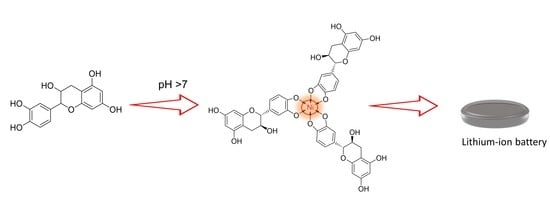
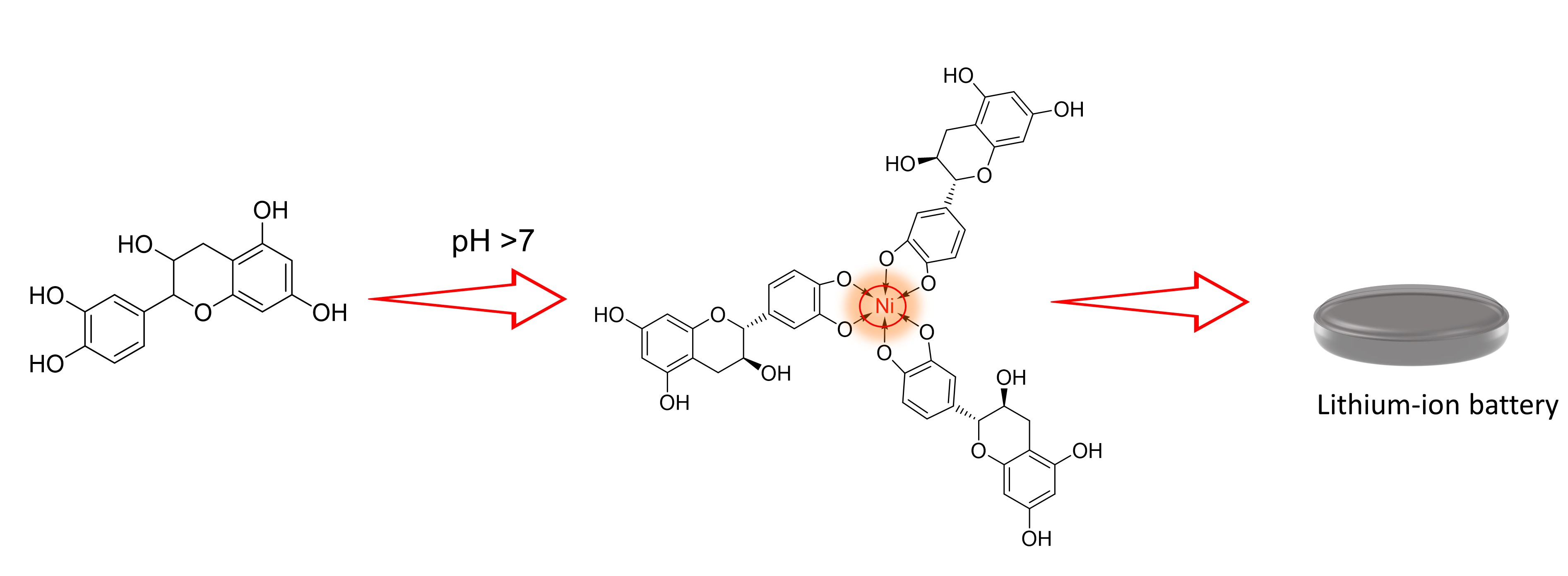
3.1. Preparation of TP-Ni

TP was bought from Shanghai Macklin Biochemical Co., Ltd., and nickel chloride hexahydrate was purchased from Aladdin Reagent Co. Ltd., Shanghai, China. All chemicals were used without further purification. In detail, the general fabrication protocol of TP-Ni was performed as follows: 1.0 g of TP was first dissolved into 20 mL of deionized water with the assistance of stirring in an ambient atmosphere. After complete dissolution, 0.275 g of NiCl2·6H2O in 5 mL of deionized water was incrementally mixed with the TP solution for 10 min, and the solution color changed to light yellow. After continually stirring at room temperature for another 1 h, the pH of the solution was then adjusted to about 8.0 with 1 M sodium hydroxide, followed by a large amount of powder precipitating from the solution. The precipitate was facilely separated by centrifugation at 9000 rpm/min for 10 min. After washing with deionized water and then ethanol 3 times, the final TP-Ni sample was obtained with a mass weight of 0.78 g (74.3%).

3.2. Electrode Preparation

After mixing 0.6 g of active material and 0.3 g of super P with a mortar, 2.0 g of a PAA aqueous solution (polymer concentration: 5 wt.%) was added to form a homogeneous slurry. The final weight proportion of active material, conductive carbon, and polymer binder is 6:3:1. The wet slurry was then homogeneously coated on a copper foil with a doctor blade. After the complete removal of the solvent (water) under vacuum at 60 °C, the electrode was prepared with a mass loading (active material) of about 1.5 mg cm2.

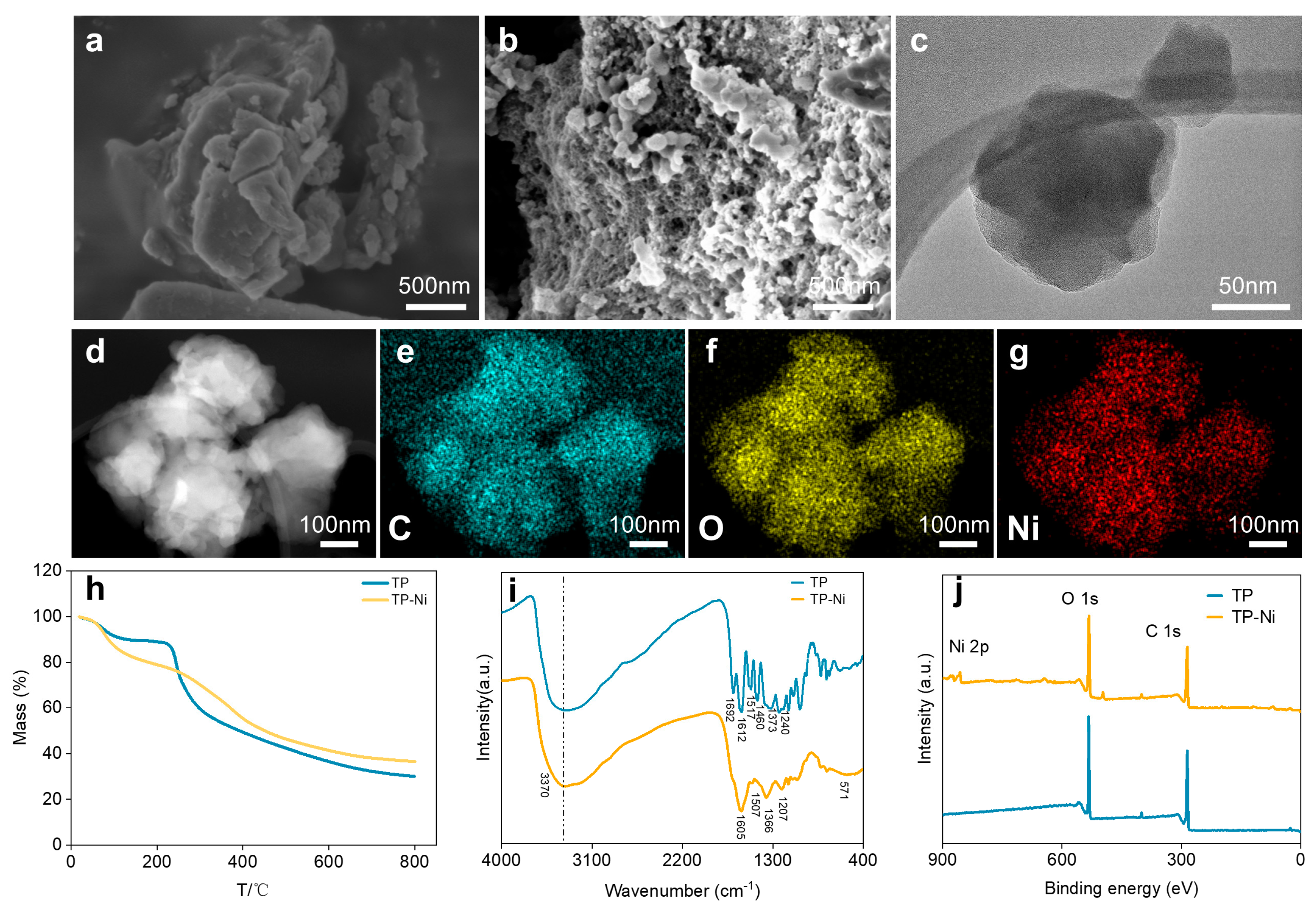
3.3. Material Characterization

Fourier transform infrared spectroscopy (FTIR) spectra of TP-Ni and TP were collected using the KBr pellet method in a range from 4000 to 400 cm−1 at ambient temperature. Powder X-ray diffraction (XRD, Rigaku Smartlab, Beijing, China) with Cu Kα radiation (λ = 0.154 nm) at 200 mA current and 45 kV voltage was used to obtain the phase and composition information of TP-Ni and TP. The bonding information of samples was determined with a confocal Raman microscope (Horiba, LABHRev-UV, Shanghai, China) using an excitation wavelength of 514 nm. Scanning electron microscopy (SEM, Zeiss Sigma, Shanghai, China) was used to obtain the morphologies of the samples at an operating voltage of 3 kV. Transmission electron microscopy (TEM), high-resolution TEM, and energy-dispersive X-ray spectroscopy (EDS) were carried out on an FEI Talos F200X. X-ray photoelectron spectroscopy (XPS, PHI 5000 VersaProbe III, Chigasaki, Japan) using Al Kα radiation was performed to characterize the chemical states of the samples.

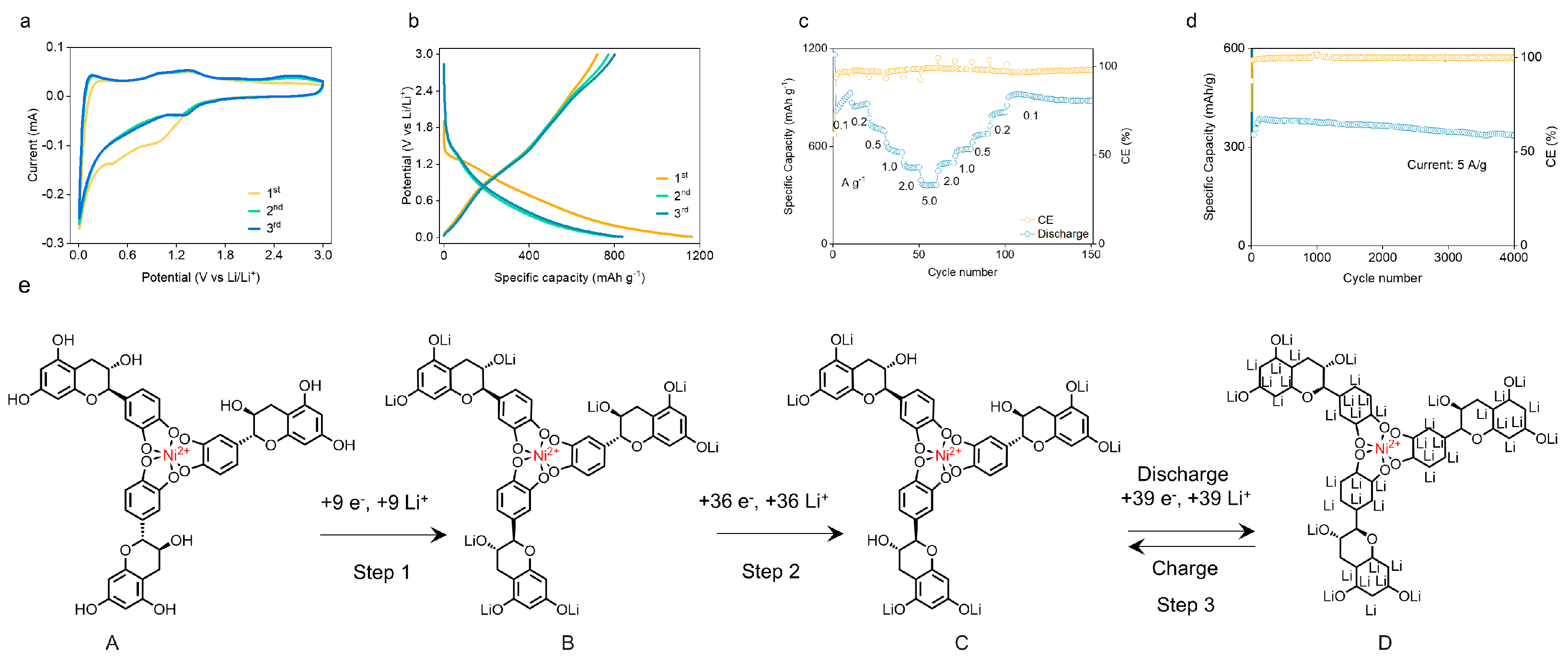
3.4. Electrochemical Measurements

The electrochemical behaviors of TP and TP-Ni electrodes were tested by using 2032 coin cells with Li foil as the counter electrode. To obtain the charge and discharge behavior, a Neware Battery Testing System was employed with a voltage range between 0.01 and 3.00 V versus Li/Li+. The electrolyte solution comprised ethylene carbonate, ethyl methyl carbonate, and dimethyl carbonate (volume ratio of 1:1:1) with 1 M LiTFSI. Cyclic voltammetry (CV) curves were recorded using an electrochemical workstation (CHI760E, Austin, TX, USA) in a voltage range of 0.01–3.00 V (vs. Li/Li+). Electrochemical impedance spectra (EIS) were collected over a frequency range of 100 kHz to 0.01 Hz at an amplitude of 5 mV.

4. Conclusions

In summary, we fabricated a novel environmentally friendly organic anode material, TP-Ni, by simply chelating tea polyphenols with nickel ions. The formation of coordination bonds, which resulted in the nanosizing of the intrinsic microstructure of TP and contributed to pseudocapacitive charging, allowed the TP-Ni anode to exhibit an impressive initial specific capacity of 1163 mAh g−1 at 0.1 A g−1 and a remarkable cycle life with a reversible specific capacity of 336 mAh g−1 at 5 A g−1 after 4000 cycles. This work offers valuable insights into the design and synthesis of novel high-performance organic electrode materials and will likely expedite their practical use in the near future.

Supplementary Materials

The following supporting information can be downloaded at https://www.mdpi.com/article/10.3390/inorganics11040148/s1: Figure S1. The synthesis of the TP-Ni compound; Figure S2. The solubility comparison of TP and TP-Ni; Figure S3. XRD profiles of TP and TP-Ni; Figure S4. XPS spectra before and after coordination of (a) Ni 2p, (b) C 1s, (c) O 1s; Figure S5. The Raman spectra of TP and TP-Ni; Figure S6. (a) Nyquist plot of EIS spectra, (b) relationship between real part of impedance and ω−0.5 in TP and TP-Ni cells; Figure S7. Galvanostatic charge and discharge curves of TP anode at a current density of 0.1 A g−1; Figure S8. Rate performance of TP anode; Figure S9. Long cycling performance measured at a current density of 1.0 A g−1; Figure S10. XPS spectra of Li 1s in TP-Ni electrodes during the first discharge/charge cycle; Figure S11. XPS spectra of Ni 2p in TP-Ni electrodes during the first discharge/charge cycle; Figure S12. The summary of impedances at different discharge/charge states in the first cycle; Figure S13. (a) Nyquist of TP-Ni anodes after different cycles. (b) The summary of impedances after different cycles; Table S1. The content of different elements in the prepared TP-Ni material according to EDS; Table S2. The Rct and DLi+ of TP and TP-Ni electrodes from EIS.

Author Contributions

Formal analysis, investigation, data curation, and visualization, Y.G.; conceptualization, investigation, and visualization, J.G.; formal analysis, visualization, and investigation, B.L.; software and validation, Y.Z.; investigation and visualization, W.L.; software and validation, J.J.; visualization, J.X.; visualization, J.S.; visualization, J.L.; supervision, project administration, and funding acquisition, H.S.; Y.G., J.G. and B.L. contributed equally to this work. All authors have read and agreed to the published version of the manuscript.

Funding

This research was funded by the Guangdong-Hong Kong-Macao Joint Laboratory (grant no. 2019B121205001) and the Macau Science and Technology Development Fund (FDCT) (project no. 0098/2020/A2); this work was also partially supported by the FDCT-MOST joint project (grant no. 0026/2022/AMJ).

Data Availability Statement

Data are contained within the article.

Conflicts of Interest

The authors declare no conflict of interest.

References

  1. Etacheri, V.; Marom, R.; Elazari, R.; Salitra, G.; Aurbach, D. Challenges in the Development of Advanced Li-Ion Batteries: A Review. Energy Environ. Sci. 2011, 4, 3243–3262. [Google Scholar] [CrossRef]
  2. Nitta, N.; Wu, F.; Lee, J.T.; Yushin, G. Li-Ion Battery Materials: Present and Future. Mater. Today 2015, 18, 252–264. [Google Scholar] [CrossRef]
  3. Li, M.; Lu, J.; Chen, Z.; Amine, K. 30 Years of Lithium-Ion Batteries. Adv. Mater. 2018, 30, 1800561. [Google Scholar] [CrossRef] [PubMed] [Green Version]
  4. Fu, K.; Gong, Y.; Liu, B.; Zhu, Y.; Xu, S.; Yao, Y.; Luo, W.; Wang, C.; Lacey, S.D.; Dai, J.; et al. Toward Garnet Electrolyte–Based Li Metal Batteries: An Ultrathin, Highly Effective, Artificial Solid-State Electrolyte/Metallic Li Interface. Sci. Adv. 2017, 3, e1601659. [Google Scholar] [CrossRef] [Green Version]
  5. Liu, B.; Zhang, J.-G.; Xu, W. Advancing Lithium Metal Batteries. Joule 2018, 2, 833–845. [Google Scholar] [CrossRef] [Green Version]
  6. Xie, L.; Tang, C.; Bi, Z.; Song, M.; Fan, Y.; Yan, C.; Li, X.; Su, F.; Zhang, Q.; Chen, C. Hard Carbon Anodes for Next-Generation Li-Ion Batteries: Review and Perspective. Adv. Energy Mater. 2021, 11, 2101650. [Google Scholar] [CrossRef]
  7. Guo, X.; Wang, C.; Wang, W.; Zhou, Q.; Xu, W.; Zhang, P.; Wei, S.; Cao, Y.; Zhu, K.; Liu, Z.; et al. Vacancy Manipulating of Molybdenum Carbide MXenes to Enhance Faraday Reaction for High Performance Lithium-Ion Batteries. Nano Res. Energy 2022, 1, e9120026. [Google Scholar] [CrossRef]
  8. Xing, C.; Chen, H.; Zhang, S. Powering 10-Ah-Level Li-S Pouch Cell via a Smart “Skin”. Matter 2022, 5, 2523–2525. [Google Scholar] [CrossRef]
  9. Sun, H.; Xin, G.; Hu, T.; Yu, M.; Shao, D.; Sun, X.; Lian, J. High-Rate Lithiation-Induced Reactivation of Mesoporous Hollow Spheres for Long-Lived Lithium-Ion Batteries. Nat. Commun. 2014, 5, 4526. [Google Scholar] [CrossRef] [Green Version]
  10. Kundu, D.; Talaie, E.; Duffort, V.; Nazar, L.F. The Emerging Chemistry of Sodium Ion Batteries for Electrochemical Energy Storage. Angew. Chem. Int. Ed. 2015, 54, 3431–3448. [Google Scholar] [CrossRef]
  11. Peters, J.F.; Baumann, M.; Zimmermann, B.; Braun, J.; Weil, M. The Environmental Impact of Li-Ion Batteries and the Role of Key Parameters—A Review. Renew. Sustain. Energy Rev. 2017, 67, 491–506. [Google Scholar] [CrossRef]
  12. Shetti, N.P.; Dias, S.; Reddy, K.R. Nanostructured Organic and Inorganic Materials for Li-Ion Batteries: A Review. Mater. Sci. Semicond. Process. 2019, 104, 104684. [Google Scholar] [CrossRef]
  13. Zhang, K.; Hu, Z.; Tao, Z.; Chen, J. Inorganic & Organic Materials for Rechargeable Li Batteries with Multi-Electron Reaction. Sci. China Mater. 2014, 57, 42–58. [Google Scholar]
  14. Lee, S.; Hong, J.; Kang, K. Redox-Active Organic Compounds for Future Sustainable Energy Storage System. Adv. Energy Mater. 2020, 10, 2001445. [Google Scholar] [CrossRef]
  15. Xie, X.; Criddle, C.; Cui, Y. Design and Fabrication of Bioelectrodes for Microbial Bioelectrochemical Systems. Energy Environ. Sci. 2015, 8, 3418–3441. [Google Scholar] [CrossRef]
  16. Hussain, I.; Lamiel, C.; Sufyan Javed, M.; Sahoo, S.; Ahmed, M.; Chen, X.; Zhang, K. Plant- and Fungi-Inspired Hierarchical Structures as Electrode Materials: A Review. Mater. Chem. Front. 2022, 6, 3460–3488. [Google Scholar] [CrossRef]
  17. Lee, B.; Ko, Y.; Kwon, G.; Lee, S.; Ku, K.; Kim, J.; Kang, K. Exploiting Biological Systems: Toward Eco-Friendly and High-Efficiency Rechargeable Batteries. Joule 2018, 2, 61–75. [Google Scholar] [CrossRef] [Green Version]
  18. Wu, Y.; Zeng, R.; Nan, J.; Shu, D.; Qiu, Y.; Chou, S.-L. Quinone Electrode Materials for Rechargeable Lithium/Sodium Ion Batteries. Adv. Energy Mater. 2017, 7, 1700278. [Google Scholar] [CrossRef]
  19. Williams, D.L.; Byrne, J.J.; Driscoll, J.S. A High Energy Density Lithium/Dichloroisocyanuric Acid Battery System. J. Electrochem. Soc. 1969, 116, 2. [Google Scholar] [CrossRef]
  20. Shimizu, A.; Tsujii, Y.; Kuramoto, H.; Nokami, T.; Inatomi, Y.; Hojo, N.; Yoshida, J. Nitrogen-Containing Polycyclic Quinones as Cathode Materials for Lithium-Ion Batteries with Increased Voltage. Energy Technol. 2014, 2, 155–158. [Google Scholar] [CrossRef]
  21. Pringle, J.M.; Efthimiadis, J.; Howlett, P.C.; Efthimiadis, J.; MacFarlane, D.R.; Chaplin, A.B.; Hall, S.B.; Officer, D.L.; Wallace, G.G.; Forsyth, M. Electrochemical Synthesis of Polypyrrole in Ionic Liquids. Polymer 2004, 45, 1447–1453. [Google Scholar] [CrossRef]
  22. Momma, T.; Nishimura, K.; Osaka, T.; Kondo, N.; Nakamura, S. Electrochemical Properties of a Polypyrrole/Polystyrenesulfonate Composite Film and Its Application to Rechargeable Lithium Battery Cathodes. J. Electrochem. Soc. 1994, 141, 2326. [Google Scholar] [CrossRef]
  23. Nishide, H.; Suga, T. Organic Radical Battery. Electrochem. Soc. Interface 2005, 14, 32. [Google Scholar] [CrossRef]
  24. Nishide, H.; Iwasa, S.; Pu, Y.-J.; Suga, T.; Nakahara, K.; Satoh, M. Organic Radical Battery: Nitroxide Polymers as a Cathode-Active Material. Electrochim. Acta 2004, 50, 827–831. [Google Scholar] [CrossRef]
  25. Renault, S.; Brandell, D.; Gustafsson, T.; Edström, K. Improving the Electrochemical Performance of Organic Li-Ion Battery Electrodes. Chem. Commun. 2013, 49, 1945–1947. [Google Scholar] [CrossRef] [PubMed]
  26. Novák, P.; Müller, K.; Santhanam, K.S.V.; Haas, O. Electrochemically Active Polymers for Rechargeable Batteries. Chem. Rev. 1997, 97, 207–282. [Google Scholar] [CrossRef] [PubMed]
  27. Jung, S.-K.; Hwang, I.; Chang, D.; Park, K.-Y.; Kim, S.J.; Seong, W.M.; Eum, D.; Park, J.; Kim, B.; Kim, J.; et al. Nanoscale Phenomena in Lithium-Ion Batteries. Chem. Rev. 2020, 120, 6684–6737. [Google Scholar] [CrossRef] [PubMed]
  28. Gorzalski, A.S.; Donley, C.; Coronell, O. Elemental Composition of Membrane Foulant Layers Using EDS, XPS, and RBS. J. Membr. Sci. 2017, 522, 31–44. [Google Scholar] [CrossRef] [Green Version]
  29. Juma, A.O.; Arbab, E.A.A.; Muiva, C.M.; Lepodise, L.M.; Mola, G.T. 571-Synthesis and Characterization of CuO-NiO-ZnO Mixed Metal Oxide Nanocomposite. J. Alloys Compd. 2017, 723, 866–872. [Google Scholar] [CrossRef]
  30. Varunkumar, K.; Hussain, R.; Hegde, G.; Ethiraj, A.S. Effect of Calcination Temperature on Cu Doped NiO Nanoparticles Prepared via Wet-Chemical Method: Structural, Optical and Morphological Studies. Mater. Sci. Semicond. Process. 2017, 66, 149–156. [Google Scholar] [CrossRef]
  31. Appu, M.; Wu, H.; Chen, H.; Huang, J. Tea Polyphenols Mediated Biogenic Synthesis of Chitosan-Coated Cerium Oxide (CS/CeO2) Nanocomposites and Their Potent Antimicrobial Capabilities. Env. Sci. Pollut. Res. 2022, 1–2. [Google Scholar] [CrossRef] [PubMed]
  32. Liu, W.; Li, Y.; Meng, X.; Liu, G.; Hu, S.; Pan, F.; Wu, H.; Jiang, Z.; Wang, B.; Li, Z.; et al. Embedding Dopamine Nanoaggregates into a Poly(Dimethylsiloxane) Membrane to Confer Controlled Interactions and Free Volume for Enhanced Separation Performance. J. Mater. Chem. A 2013, 1, 3713–3723. [Google Scholar] [CrossRef]
  33. Catauro, M.; Papale, F.; Bollino, F.; Piccolella, S.; Marciano, S.; Nocera, P.; Pacifico, S. Silica/Quercetin Sol–Gel Hybrids as Antioxidant Dental Implant Materials. Sci. Technol. Adv. Mater. 2015, 16, 035001. [Google Scholar] [CrossRef] [PubMed] [Green Version]
  34. Kalinowska, M.; Świderski, G.; Matejczyk, M.; Lewandowski, W. Spectroscopic, Thermogravimetric and Biological Studies of Na(I), Ni(II) and Zn(II) Complexes of Quercetin. J. Anal. Calorim. 2016, 126, 141–148. [Google Scholar] [CrossRef] [Green Version]
  35. Wang, H.; Wang, X.; Kong, R.-M.; Xia, L.; Qu, F. Metal-Organic Framework as a Multi-Component Sensor for Detection of Fe3+, Ascorbic Acid and Acid Phosphatase. Chin. Chem. Lett. 2021, 32, 198–202. [Google Scholar] [CrossRef]
  36. Jones, C.D.; Lewis, A.R.; Jones, D.R.; Ottley, C.J.; Liu, K.; Steed, J.W. Lilypad Aggregation: Localised Self-Assembly and Metal Sequestration at a Liquid–Vapour Interface. Chem. Sci. 2020, 11, 7501–7510. [Google Scholar] [CrossRef] [PubMed]
  37. Matienzo, J.; Yin, L.I.; Grim, S.O.; Swartz, W.E., Jr. X-ray Photoelectron Spectroscopy of Nickel Compounds. Inorg. Chem. 1973, 12, 2762–2769. [Google Scholar] [CrossRef]
  38. Jurasekova, Z.; Domingo, C.; Garcia-Ramos, J.V.; Sanchez-Cortes, S. Effect of PH on the Chemical Modification of Quercetin and Structurally Related Flavonoids Characterized by Optical (UV-Visible and Raman) Spectroscopy. Phys. Chem. Chem. Phys. 2014, 16, 12802–12811. [Google Scholar] [CrossRef] [Green Version]
  39. Kim, S.; Regitsky, A.U.; Song, J.; Ilavsky, J.; McKinley, G.H.; Holten-Andersen, N. In Situ Mechanical Reinforcement of Polymer Hydrogels via Metal-Coordinated Crosslink Mineralization. Nat. Commun. 2021, 12, 667. [Google Scholar] [CrossRef]
  40. Liu, X.; Weng, Q.; Liu, T.; Tang, Z.; Tang, H. A Li3PO4 Coating Strategy to Enhance the Li-Ion Transport Properties of Li2ZnTi3O8 Anode Material for Lithium-Ion Battery. Electrochim. Acta 2023, 447, 142151. [Google Scholar] [CrossRef]
  41. Tang, S.B.; Lai, M.O.; Lu, L. Study on Li+-Ion Diffusion in Nano-Crystalline LiMn2O4 Thin Film Cathode Grown by Pulsed Laser Deposition Using CV, EIS and PITT Techniques. Mater. Chem. Phys. 2008, 111, 149–153. [Google Scholar] [CrossRef]
  42. Yang, X.; Rogach, A.L. Electrochemical Techniques in Battery Research: A Tutorial for Nonelectrochemists. Adv. Energy Mater. 2019, 9, 1900747. [Google Scholar] [CrossRef]
  43. Xia, S.-B.; Yao, L.-F.; Guo, H.; Shen, X.; Liu, J.-M.; Cheng, F.-X.; Liu, J.-J. Li+ Intercalcation Pseudocapacitance in Sn-Based Metal-Organic Framework for High Capacity and Ultra-Stable Li Ion Storage. J. Power Sources 2019, 440, 227162. [Google Scholar] [CrossRef]
  44. Zhang, G.; Yang, Y.; Zhang, T.; Xu, D.; Lei, Z.; Wang, C.; Liu, G.; Deng, Y. FeIII Chelated Organic Anode with Ultrahigh Rate Performance and Ultra-Long Cycling Stability for Lithium-Ion Batteries. Energy Storage Mater. 2020, 24, 432–438. [Google Scholar] [CrossRef]
  45. Li, B. Surface Modification of Natural Graphite by Phenolic Resin Carbon Coating for Improvement of Cyclic Performances in Lithium Ion Batteries. Energy Sources 2003, 25, 827–836. [Google Scholar] [CrossRef]
  46. Xu, S.; Zhang, Z.; Wu, T.; Xue, Y. Nanoporous Carbon Microspheres as Anode Material for Enhanced Capacity of Lithium Ion Batteries. Ionics 2018, 24, 99–109. [Google Scholar] [CrossRef]
  47. Li, C.; Liu, B.; Jiang, N.; Ding, Y. Elucidating the Charge-Transfer and Li-Ion-Migration Mechanisms in Commercial Lithium-Ion Batteries with Advanced Electron Microscopy. Nano Res. Energy 2022, 1, e9120031. [Google Scholar] [CrossRef]
  48. Zhang, H.; Zhong, L.; Xie, J.; Yang, F.; Liu, X.; Lu, X. A COF-Like N-Rich Conjugated Microporous Polytriphenylamine Cathode with Pseudocapacitive Anion Storage Behavior for High-Energy Aqueous Zinc Dual-Ion Batteries. Adv. Mater. 2021, 33, 2101857. [Google Scholar] [CrossRef]
  49. Shen, K.; Chen, H.; Qin, H.; Hou, X. Construct Pseudo-Capacitance of a Flexible 3D-Entangled Carbon Nanofiber Film as Freestanding Anode for Dual-Ion Full Batteries. J. Mater. Sci. Mater. Electron. 2020, 31, 10962–10969. [Google Scholar] [CrossRef]
  50. Patil, D.R.; Koteswararao, B.; Begari, K.; Yogi, A.; Moussa, M.; Dubal, D.P. Cobalt Cyclotetraphosphate (Co2P4O12): A New High-Performance Electrode Material for Supercapacitors. ACS Appl. Energy Mater. 2019, 2, 2972–2981. [Google Scholar] [CrossRef]
Figure 1. (a,b) SEM images of TP and TP−Ni, respectively. (c) TEM image of TP−Ni. (dg) The HRTEM image of TP−Ni and the corresponding elemental mapping images of C (blue), O (yellow), and Ni (red), respectively. (h) TGA of TP and TP−Ni. (i) The FTIR spectrum of TP−Ni and TP. (j) The XPS profile of TP−Ni and TP.
Inorganics 11 00148 g001
Figure 2. (a) CV curves of TP−Ni measured at a scan rate of 0.1 mV s−1 in the voltage range of 0.01–3.0 V. (b) Charge/discharge curves measured at a current density of 0.1 A g−1 from 0.01 to 3.0 V. (c) Rate performance of TP−Ni. (d) Long cycling performance measured at a current density of 5 A g−1. (e) The proposed mechanism for storing lithium in the TP−Ni anode.
Inorganics 11 00148 g002
Figure 3. (a) The selected points for XPS measurements at various electrochemical states. XPS spectra of (b) C 1s and (c) O 1s of TP−Ni electrodes at different discharge/charge states.
Inorganics 11 00148 g003
Figure 4. (af) The microstructural changes of TP-Ni electrodes in different electrochemical states. Scale bar: 1 μm. (g) Nyquist plots of TP-Ni electrodes in different electrochemical states during the first discharge/charge cycle.
Inorganics 11 00148 g004
Figure 5. (a) CV profiles of TP−Ni with different scan rates. (b) Capacitance contribution for TP−Ni. (c) Relationship between the logarithm peak current and logarithm scan rates. (d) Contribution ratio of capacitive capacity at different scan rates.
Inorganics 11 00148 g005
Disclaimer/Publisher’s Note: The statements, opinions and data contained in all publications are solely those of the individual author(s) and contributor(s) and not of MDPI and/or the editor(s). MDPI and/or the editor(s) disclaim responsibility for any injury to people or property resulting from any ideas, methods, instructions or products referred to in the content.

