Abstract
High-energy cathode materials that are Li- and Mn-rich lithiated oxides—for instance, 0.35Li2MnO3.0.65LiNi0.35Mn0.45Co0.20O2 (HE-NCM)—are promising for advanced lithium-ion batteries. However, HE-NCM cathodes suffer from severe degradation during cycling, causing gradual capacity loss, voltage fading, and low-rate capability performance. In this work, we applied an effective approach to creating a nano-sized surface layer of Li2SO4 on the above material, providing mitigation of the interfacial side reactions while retaining the structural integrity of the cathodes upon extended cycling. The Li2SO4 coating was formed on the surface of the material by mixing it with nanocrystalline Li2SO4 and annealing at 600 °C. We established enhanced electrochemical behavior with ~20% higher discharge capacity, improved charge-transfer kinetics, and higher rate capability of HE-NCM cathodes due to the presence of the Li2SO4 coating. Online electrochemical mass spectrometry studies revealed lower CO2 and H2 evolution in the treated samples, implying that the Li2SO4 layer partially suppresses the electrolyte degradation during the initial cycle. In addition, a ~28% improvement in the thermal stability of the Li2SO4-treated samples in reactions with battery solution was also shown by DSC studies. The post-cycling analysis allowed us to conclude that the Li2SO4 phase remained on the surface and retained its structure after 100 cycles.
1. Introduction
Li- and Mn-rich oxides of transition metals Ni, Mn, and Co, such as 0.35Li2MnO3.0.65LiNi0.35Mn0.45Co0.20O2 (HE-NCM), are desirable candidates for high-energy cathode materials for Li-ion batteries. These layered–layered structure high-energy materials have attracted much attention since they were first synthesized and introduced by Thackeray et al. [1,2] and have been studied intensively by many groups [3,4]. These materials are composed of two-layered structure components: a Li2MnO3 (space group C2/m) monoclinic phase and a LiMO2 (space group R-3m) rhombohedral phase, where M = Mn, Co, or Ni. Their general formula can be represented as xLi2MnO3·(1−x)LiMO2 (M = Mn, Ni, Co) [5]. HE-NCM materials can provide a high energy density of ~1000 Wh/Kg due to a higher specific capacity (>250 mAh g−1) and wide operating voltage window (2.0–4.8 V vs. Li/Li+), thereby being suitable for next-generation battery technologies, including large-scale energy storage applications such as EVs and PHEVs [6]. However, intrinsic challenges for practical application still exist and need to be resolved before HE-NCM can meet the demands of commercial and industrial applications. The main drawbacks of HE-NCM materials are as follows: low initial columbic efficiency due to the irreversible de-intercalation of Li ions and release of oxygen molecules by oxidation, irreversible structural changes resulting in capacity fading during prolonged cycling, and voltage hysteresis. In addition, HE-NCM electrodes demonstrate poor kinetics and rate capability, crack formation, dislocation evolution upon cycling, and degradation of the electrolyte solution at high potentials of 4.8 V vs. Li/Li+ upon charging. Over the years, substantial effort has been invested in solving the above challenges. For instance, partial substitutions of transition metals using cationic, anionic, or co-doping of both cationic and anionic, which stabilized voltage fading and resulted in steady electrochemical performance, was proposed by several groups [7,8,9,10,11]. Moreover, great attention was given to the surface stabilization of the HE-NCM materials by depositing uniform thin films on the surface using atomic layer deposition (ALD). This improves the stability of the electrode active mass during the first cycle activation and at cycling to high potentials [12,13]. The most familiar coating using ALD is Al2O3 [12,14,15], but many other metal oxide and metal fluoride coatings, including TiO2 [16], CeO2 [17], AlPO4 [18], AlF3 [19], were used on HE-NCM materials. Recently, we have demonstrated that ALD coatings such as Al2O3, Li5AlO4, and Na5AlO4 on HE-NCM substantially improved the electrochemical behavior of the coated materials tested in coin-type Li cells at 30 °C and in full cells vs. graphite anode [20,21]. The main results obtained in these studies included lower evolution of the voltage hysteresis, less gas release (O2, CO2, H2, etc.), morphological integrity of the particles, improved thermal stability, and lower transition metal dissolution during prolonged cycling compared to the uncoated materials. Overall, the coatings act as a buffer zone that mitigates undesirable side reactions between the electrodes and the electrolyte solutions [20,21]. It was shown in several reports that the thermal treatment of HE-NCM materials with reactive gases (NH3 [22], F2 [23], NF3 [24], CO2 [25], and SO2 [26]) at a high temperature can be considered an effective approach in decreasing the capacity loss and protecting the cathode’s surface from undesired side reactions at high potentials [27]. We demonstrated in our previous work that SO2 thermal gas treatment on HE-NCM cathode materials resulted in the formation of surface sulfates and sulfites, while the bulk remained unaffected. The gas treatment resulted in increased discharge capacity during cycling, higher rate capability, lower evolution of the voltage hysteresis, and lower heat evolved upon chemical reactions of the gas-treated samples with solution species in a wide temperature range of 25–350 °C. These improved characteristics were related to Li2SO4 (and other sulfates) that were formed and served as a steady surface. Importantly, the Li2SO4 phase was structurally stable and remained on the surface even after prolonged cycling [27]. Zhang et al. used elemental sulfur as a cathode slurry additive that formed Li2S2O3 further oxidized to Li2SO4 species on LiNi0.80Co0.10Mn0.10O2(NCM811) cathode surface, improving thus rate capability performance and lowering both the surface layer resistance and charge-transfer resistance of the cathode. [28]. Pan et al. added Li2SO4 as a component in the synthesis of LiMnPO4 (olivine structure) cathode material to overcome its two major challenges: slow Li+ diffusion speed and low electronic conductivity. This modified LiMnPO4 exhibited higher discharge capacity, improved rate capability, and more stable cycling behavior [29]. Dingding Lv et al. modified the surface of LiNi1/3Co1/3Mn1/3O2 with Li2O-B2O3-Li2SO4, exhibiting enhanced electrochemical performance at high cycling rates and low temperatures, as well as reducing the interfacial resistance towards lithium-ion migration [30]. A mixture of LiCoO2 and Li2SO4 was reported to provide high formability and high ionic conductivity for all-oxide solid-state cells [31]. Savina et al. have shown that amorphous Li2SO4 can serve as a binder located at the grain boundaries and intergranular contacts of the primary NMC811 crystallites, enhancing the capacity retention and rate capability of these cathodes cycled within the 2.7–4.3 V vs. Li/Li+ voltage window [32].
To the best of our knowledge, the surface modification of HE-NCM cathode materials with Li2SO4 has not been studied yet. The main goal of the present work was therefore to elucidate the effect of Li2SO4 treatment on the electrochemical behavior of HE-NCM cathodes in Li cells. We have used herein a simple, relatively safe, and environmentally friendly procedure of mechanical mixing and ball milling of HE-NCM with Li2SO4 followed by annealing the mixture at 600 °C. From the microscopic imaging and electron diffraction analysis, we concluded that the Li2SO4 coating was produced as a homogeneous nano-sized layer on the HE-NCM materials. This layer was well preserved, retaining its structure upon prolonged cycling of HE-NCM electrodes in Li cells. We aimed also to demonstrate that the serious safety hazards related to the gas treatment of these materials by SO2, NH3 (as studied in previous work [22,27]) can be eliminated, resulting thus in more environmentally friendly and lower-cost chemistry. Our findings demonstrate improved kinetics, higher discharge capacity at a high rate (up to 4C), and enhanced thermal stability in battery solution, i.e., less heat evolution compared to the untreated HE-NCM cathode samples. Furthermore, the results point out that using a simple experimental procedure, the surface of HE-NCM materials is effectively protected by the Li2SO4 nano-sized layer, resulting thus in improving the electrochemical characteristics and thermal stability of Li- and Mn-rich cathodes.
2. Materials and Methods
Li- and Mn-rich material 0.35Li2MnO3.0.65LiNi0.35Mn0.45Co0.20O2 (HE-NCM) was obtained from BASF SE, Germany. Crystalline lithium sulfate Li2SO4 from Sigma-Aldrich (particle size around 50–100 nm as measured by TEM in our lab) was added (5 wt.%) to the above Li-rich active material and the mixture was ball-milled in a Planetary Mono Mill PULVERISETTE 6 classic line (FRITSCH, Markt Einersheim, Germany) using five ZrO2 balls, at 400 rpm for 1 h. The ratio between the powder and the balls was 0.31. The mixture obtained was further annealed at 600 °C in a tube furnace under pure nitrogen for 2 h. Composite electrodes were prepared from slurry of 80% active Li- and Mn-rich material, 5% Super P carbon black from Timcal, Bodio, Switzerland, 5% KS-6 graphite (Timcal, Bodio, Switzerland), and 10% PVDF (Solef 5130 from Solvay, Brussels, Belgium) in N-methyl pyrrolidone. Slurry was prepared in a Thinky planetary vacuum mixer (Tokyo, Japan) and then cast using a doctor blade onto an aluminum foil (15 µm thick, from Strem Chemicals, Newburyport, MA, USA), dried on a hotplate, followed by drying at 120 °C under vacuum overnight. The electrochemical measurements were performed using a multichannel Maccor-2000 battery cycler and a battery test unit model 1470, coupled with a frequency response analyzer model 1255 from Solartron, Inc., Shildon, Durham, UK, driven by Corrware and ZPlot software (from Scribner Associates, Inc., Southern Pines, NC, USA). The alternating voltage amplitude in impedance measurements was 3 mV, and the frequency ranged from 100 kHz to 5 mHz. Electrochemical testing of untreated and Li2SO4-treated HE-NCM cathode materials was carried out by galvanostatic cycling in half-cells of coin-type 2325 (parts from NRC-CNRC, Ottawa, Ontario, Canada). They comprised HE-NCM cathodes, Li metal foil (~200-μm thick from Honjo Metal Co., Osaka, Japan) as counter-electrodes, Celgard 2500 polypropylene separators, and ethylene carbonate (EC)–ethyl methyl carbonate (EMC) (3:7 v/v %) 1M LiPF6 Li-battery grade electrolyte solutions LP57 from BASF SE, Ludwigshafen, Germany. Electrode loading was ~3 mg of active HE-NCM material per cm2 corresponding to 0.75 mAh/cm2 areal loading (considering 250 mAh/g at a 1C rate). Electrochemical cells were assembled in a glovebox (VAC, from Hawthorne, CA, USA) filled with highly pure argon (5N, Maxima, Ashdod, Israel). All cells were subjected to cycling at 30 °C, as follows: the first activation step was performed from OCV to 4.7 V in charge and 2.0 V in discharge vs. Li/Li+, at a C/15 rate, C defined as 250 mAh g−1. All subsequent cycles were performed from 2.0 to 4.6 V. For the first cycle, a constant voltage step for 3 h was applied at the anodic limit; all subsequent constant voltage steps were for 30 min. After the initial formation cycle at a C/15 rate, we performed two cycles at C/10, followed by three cycles at C/3, 0.8C, 1C, 2C, 4C, and 0.1C, after which 80 cycles were performed at C/3, and then the cycling was terminated. For statistical purposes, we studied at least 2–3 electrochemical cells simultaneously and the results were averaged.
For XRD measurements from powder HE-NCM samples, we employed a Bruker D8 Advance X-ray diffractometer using CuKα radiation. The intensities were recorded within the 2θ range from 10° to 80° with 2θ steps of ≈0.0194°. A computer program, RIETICA, was used for the Rietveld analysis. The peak shape was described by a pseudo-Voigt function [33] with refinable γ-parameter presenting the relation between Gaussian and Lorentzian; the line width (FWHM) was described by the Caglioti function [34] with three refinable parameters U, V, W. The background was modeled using linear interpolation between a set of fixed points. Morphological characteristics were analyzed using SEM Ouanta FEG 250 FEI with resolutions down to 1.2 nm. TEM examinations were carried out with a LaB6-200 kV Jeol-2100 transmission electron microscope operated at 200 kV. Specimens of Li-rich materials for observation in TEM were prepared onto lacey carbon grids. We carried out XPS measurements on the 5600 Multi-Technique System (PHI, Chanhassen, MN, USA) using UHV (2.5 × 10⁻¹⁰ Torr base pressure) and the carbon C 1s peak at 285 eV as the energy reference. These measurements were performed by transferring the HE-NCM materials to the instrument under pure argon in a particular vessel without exposure to the ambient atmosphere. A ratio of Lorentzian and Gaussian functions was used for the least-squares curve fitting procedure, utilizing a Shirley or Linear background subtraction. For online electrochemical mass spectrometry (OEMS), the cells contained Li metal foil (ø 14 mm) as anodes, HE-NCM composite cathodes (ø 10 mm), and two polypropylene separators (ø 19 mm). They were filled with 100 µL of LP57 electrolyte solution and connected to OEMS (HPR-40, Hiden Analytical, Warrington, UK) [35,36] using a microcapillary inlet with a sample rate of 12 µL/min. The electrochemical measurements were carried out using a VSP potentiostat (Bio-logic Science Instruments, Seyssinet-Pariset, France) in a potential window of 2–4.8 V. For the in-operando measurements of the evolved gases as a function of applied potential, Mid mode was selected for H2, CO2, and O2 gases. The thermal analyses of HE-NCM samples by DSC were performed in the temperature range from 25 °C to 400 °C (DSC 3 + STARe System, METTLER TOLEDO) using closed reusable high-pressure gold-plated stainless-steel crucibles (30 µL in volume). We carried out all the weighing measurements using a microbalance (Mettler Toledo AB135-S/FACT, Columbus, OH, USA) inside an argon-filled glovebox.
3. Results and Discussion
3.1. Material Characterization
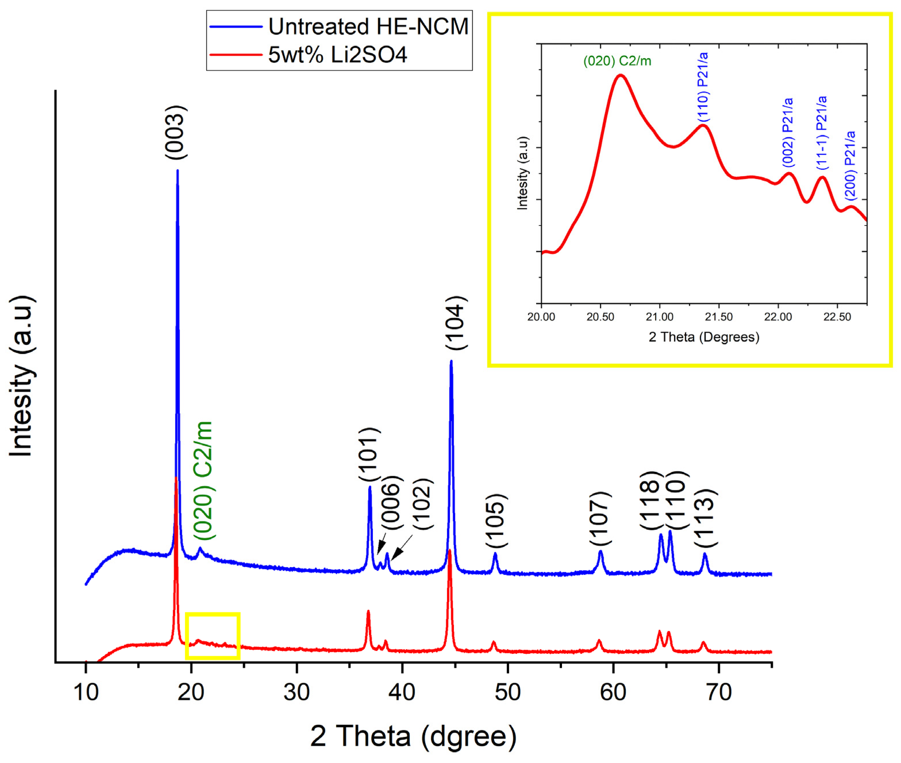
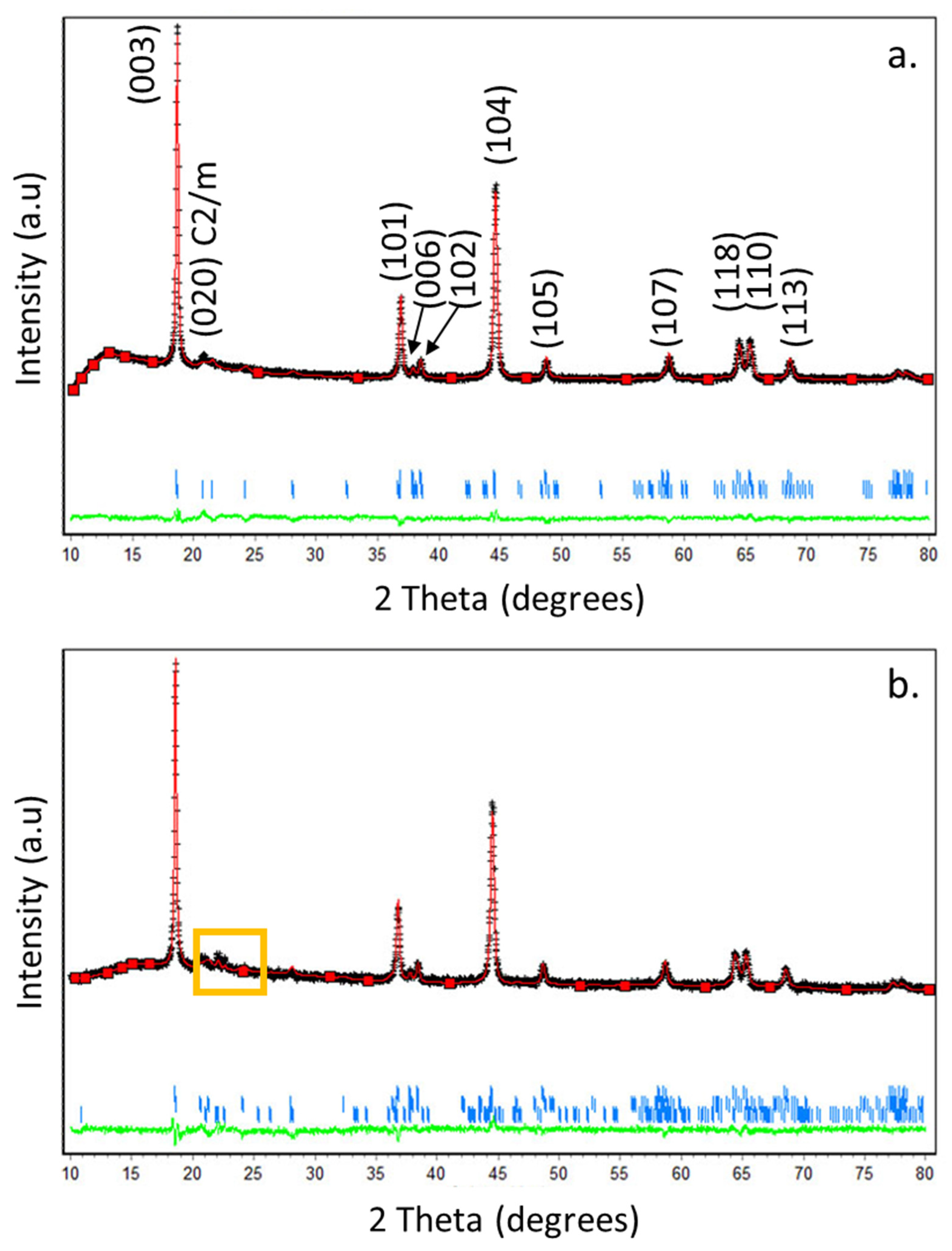
From the morphological viewpoint, HE-NCM 0.35Li2MnO3.0.65LiNi0.35Mn0.45Co0.20O2 particles are ball-shaped and around ~5–15 µm in diameter, as measured by scanning electron microscopy [27]. It is important to note that their morphology was intact after ball milling with Li2SO4 and annealing the mixture at 600 °C under pure nitrogen. The XRD patterns of untreated HE-NCM and Li2SO4-treated materials are shown in Figure 1. The main peaks could be indexed in terms of the rhombohedral structure of the α-NaFeO2 type (space group R-3m). Well-resolved peak pairs of (006)/(012) and (018)/(110) around 2Theta of 38° and 65° indicate the well-developed layered structure [37]. The diffraction peaks between 2Theta of 20 and 25° reflect the presence of the monoclinic phase Li2MnO3 [38]. The insert, which is an enlargement of 2Theta range 19–23° (yellow square), shows the additional most intense peaks of the Li2SO4 phase. These peaks at 2Theta = 21.4°, 22.08°, 22.3°, and at 22.6° are related to the Li2SO4 monoclinic phase P21/a (110), (002), (11-1), and (200), respectively (PDF 01-073-1250). The slight shift in the 2Theta compared to the peaks from the powder diffraction file (PDF) of Li2SO4 is due to the annealing process at 600 °C for 2 h under N2 gas and slow cooling back to room temperature, as will be discussed in the next paragraph. The Rietveld analysis plots obtained for HE-NCM pristine and Li2SO4-treated material are shown, respectively, in Figure 2a,b, and the corresponding cell parameters are represented in Table 1. For the Rietveld calculations, the HE-NCM pristine material was considered to be composed of two constituents: monoclinic component Li2MnO3 (C2/m) and rhombohedral component LiMO2 (R-3m) (M = Mn, Ni, Co). The calculated pattern is shown by the red curve. The fit to the experimental profile is good, described by the values of Rp and Rwp factors 1.11 and 1.43, respectively. The calculated weight fractions, obtained for the rhombohedral and monoclinic components (68.4 % and 31.6 %, respectively), are also in good agreement with the declared composition of the material. The model used for the refinement of Li2SO4-treated material (see Figure 2b) was based on a three-phase system, which, in addition to the rhombohedral and monoclinic components, contained the Li2SO4 (P21/a) monoclinic phase. The calculated quality of the profile fitting was Rp = 1.52 and Rwp = 1.94. The calculated weight fractions, obtained for the rhombohedral, monoclinic, and Li2SO4 components, are 66.7%, 29.5%, and 3.8%, respectively. The cell parameters of the HE-NCM cathode material were slightly changed after the annealing of the Li2SO4-treated sample, as shown in Table 1.

Figure 1.
XRD patterns of untreated HE-NCM material and of that treated with 5 wt.% of Li2SO4. 2Theta = 21.4°, 22.08°, 22.3°, and 22.6° are related to Li2SO4 monoclinic phase P21/a (110), (002), (11-1), and (200), respectively (PDF 01-073-1250). In the insert, there is an enlargement of 2Theta = 19–23° (yellow square) showing the additional most intense peaks of Li2SO4 (in blue). The peak at 2Theta = 20.6° (020) of the monoclinic phase (C/2m) from the HE-NCM is marked in green.

Figure 2.
(a,b) Rietveld plots for HE-NCM pristine (untreated) material and that treated with Li2SO4, respectively. The calculated patterns are shown by red curves. The difference between the observed and calculated intensities is presented by the green curve. The short vertical bars indicate the position of Bragg reflections of phases. The yellow square marks the additional most intense peaks of Li2SO4.

Table 1.
Lattice parameters of the Li2MnO3 monoclinic (C2/m), Li(TM)O2 rhombohedral (R-3m), and Li2SO4 (P21/a) phases (components) of HE-NCM materials according to XRD measurements and Rietveld analysis.
It is important to note that while annealing above 575 °C (temperature of transition from β-Li2SO4 phase to α-cubic phase) and then quenching back to room temperature, the crystal structure and conduction characteristics of Li2SO4 change substantially [39,40]. The rapid quenching of Li2SO4 enables a significant fraction of disorder retained at ambient temperatures. X-ray diffraction studies demonstrated that the quenched samples had a less ordered monoclinic β-Li2SO4 phase [40]. This thermal quenching process may break macro-crystallites into several micro-crystallites or nano-crystallites, resulting in a change in the unit cell size. Findings also suggest the introduction of an amorphous phase between reduced Li2SO4 crystalline grains. Such changes can induce disorder in the quenched samples; therefore, they exhibit enhanced ionic conductivity (by one order of magnitude), with a slight decrease in the phase transition point over the non-quenched Li2SO4 [40]. Moreover, heating above the temperature of the transition point followed by slow cooling to room temperature can also alter the physical properties of the material [39]. In the section below, we correlate the improved electrochemical characteristics, namely higher rate capability and lower charge-transfer resistance (Rct), of the Li2SO4-treated material to its heating above the transition point and slow cooling.
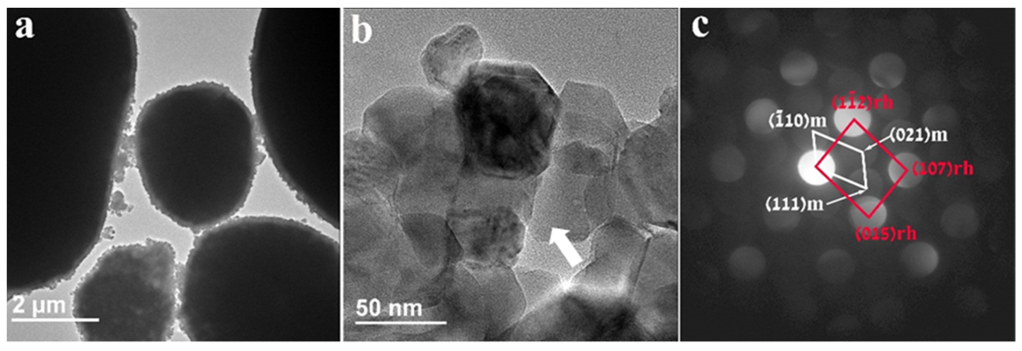
Figure 3 represents the morphological and structural information of the pristine untreated HE-NCM particles. The HE-NCM material is composed of micron-sized primary ball-shaped particles consisting of nano-sized secondary particles. Typical SEM morphological images of this material are demonstrated in our previous work [27]. The TEM micrograph in Figure 3a is a representative image showing ball-shaped primary particles of HE-NCM material. As expected, there is no coating or surface layer on these particles, while Figure 3b displays 30–70 nm-sized secondary particles (grains) and grain boundaries among them. The convergent beam electron diffraction pattern (CBED) in Figure 3c, taken from a 7 nm area from the particle marked by the white arrow in Figure 3b, was interpreted based on the two-phase system model consisting of structurally integrated layered monoclinic (m) Li2MnO3 (C2/m) and (r) rhombohedral (R-3m) LiMO2 (M = Mn, Co, or Ni) components.

Figure 3.
(a) TEM image of untreated HE-NCM displaying the typical ball-shaped “primary” particles of several micrometers in diameter; (b) 30–70 nm-sized “secondary” particles (grains); (c) CBED patterns taken from a 7 nm area from the particle marked by the white arrow. They represent the Li(TM)O2 rhombohedral R-3m (166) and Li2MnO3 monoclinic C2/m (12) phases, marked rh and m, respectively.
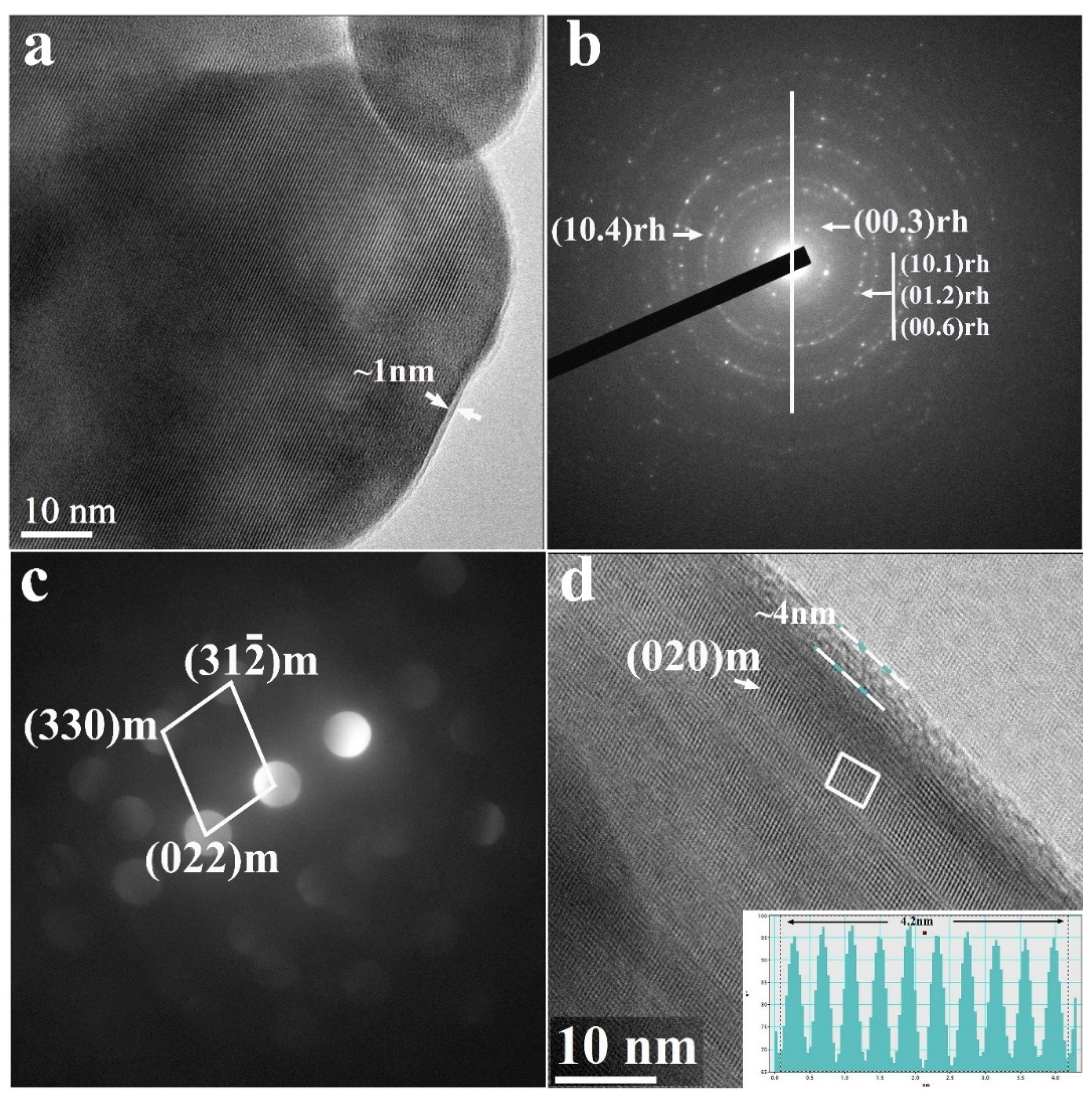
Results of TEM studies of the Li2SO4-treated HE-NCM are shown in Figure 4. We detected a thin homogenous layer of ~1 nm thickness (marked with white arrows) over the particles in Figure 4a. According to XRD studies (Figure 1), this layer is composed of Li2SO4. Energy-dispersive spectroscopy tests revealed around 1 At. % of sulfur in the treated samples. Figure 4b,c demonstrate the selected area electron diffraction (SAED) patterns of the Li(TM)O2 rhombohedral R-3m phase and convergent beam electron diffraction (CBED) patterns of the Li2MnO3 monoclinic C2/m phase, respectively. Figure 4d represents the HR-TEM image showing the characteristic lattice fringes for the Li2MnO3, while the insert presents a line of ”ten” d-spacing measuring 4.2 nm [d020 = 4.2 Å], corroborated to the (020) planes of the monoclinic phase. The TEM images (Figure 4a,d) display a thin layer of Li2SO4 (estimated thickness of 1–4 nm) as a conformal surface coating on the HE-NCM material.

Figure 4.
(a) TEM bright-field image of HE-NCM sample treated with 5 wt.% of Li2SO4, as indicated in Section 2. It shows a thin homogenous layer of around 1–4 nm thickness (marked with white arrows) composed of Li2SO4 monoclinic phase (as follows from XRD data in Figure 1). (b) SAED shows a diffraction pattern matching the Li(TM)O2 rhombohedral R-3m (166) phase. (c) CBED pattern matches with the constituent Li2MnO3 monoclinic C2/m (12) phase. (d) HRTEM image presenting the characteristic lattice fringes for the Li2MnO3 monoclinic C2/m (12) phase. The insert presents a line of ”ten” d-spacing measuring 4.2 nm [d020 = 4.2 Å] and assigned to the (020) planes of Li2MnO3.
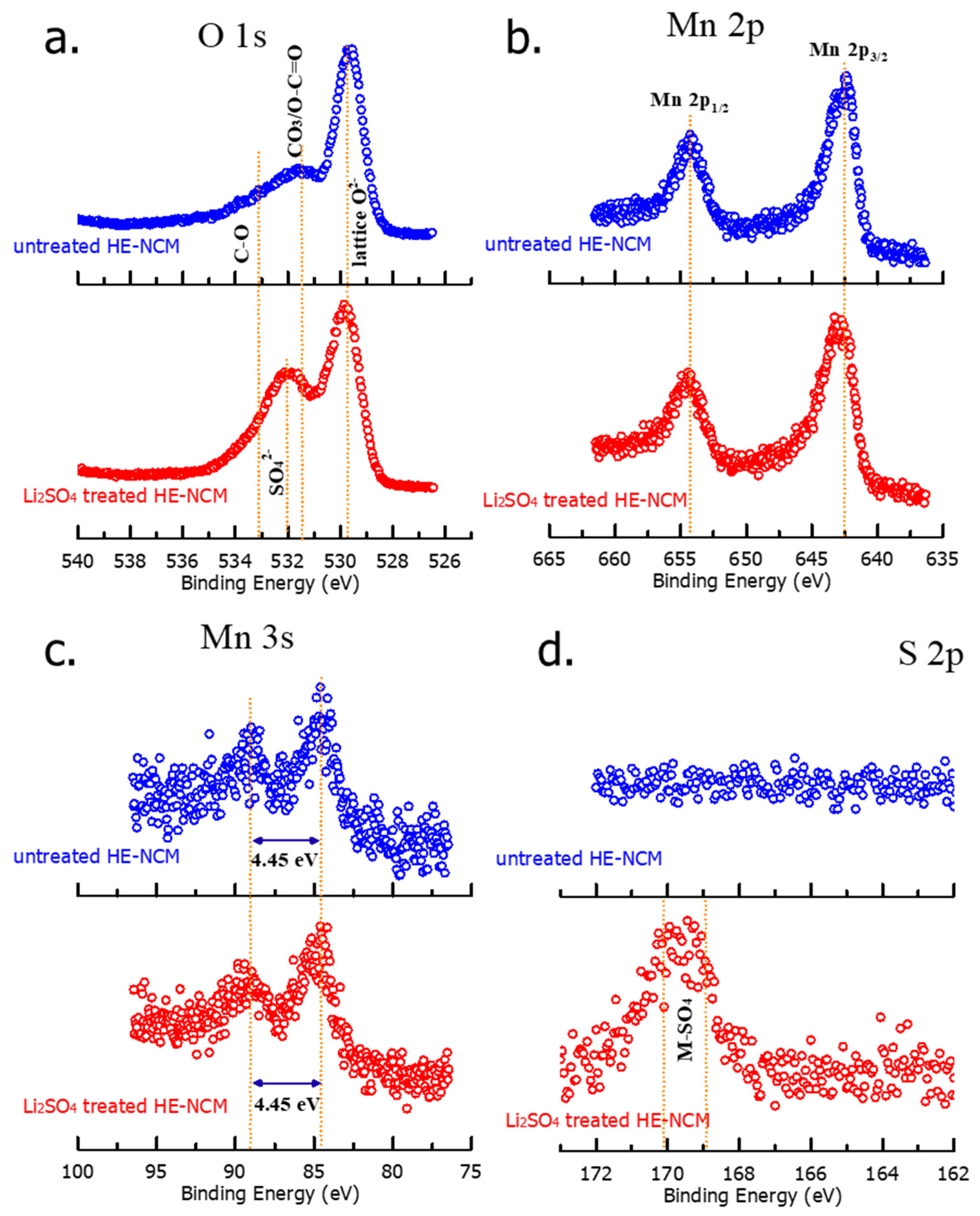
We conducted XPS measurements in order to explore the surface chemical characteristics of pristine (untreated) and Li2SO4-treated samples, shown in Figure 5. The binding energies of O 1s locate at four different positions as follows: 529.64 eV and 531.50 eV peaks, respectively, represent regular lattice oxygen, O2− in the host structure, and surface oxygen, which involves functional groups with O2−, such as CO32− [41]. At 532.01 eV, a peak of sulfate group SO42− arises as expected in the Li2SO4-treated material [42]. The spectrum of the untreated material shows a feature at 533.22 eV, probably related to species with a C-O bond on the surface [43]. XPS spectra of sulfur S 2p in Figure 5d demonstrate two characteristic peaks of Li2SO4 at ~169 eV and ~170 eV in the treated HE-NCM material, which reveals the presence of the Li2SO4 coating layer on the surface [44]. As expected, the untreated material does not contain any surface sulfate species (Figure 5d). From the results of XPS studies, we conclude that there was no influence of the Li2SO4 treatment on the oxidation states of the transition metals. This is confirmed by the fact that Mn 3s splitting of 4.45 eV did not change after the treatment, implying no variation in the oxidation state of Mn4+ [45].
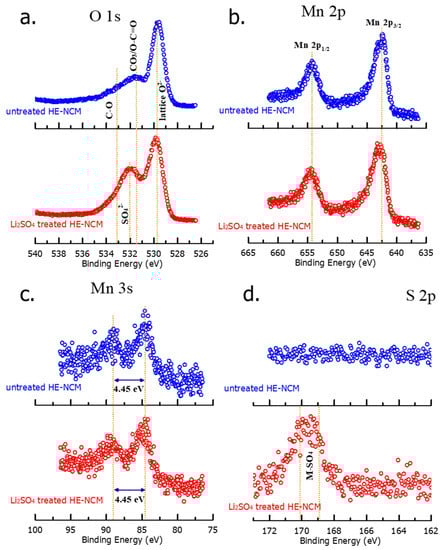
Figure 5.
XPS spectra of O 1s (a), Mn 2p (b), Mn 3s (c), and S 2p (d) measured from untreated and Li2SO4 treated HE-NCM cathode materials.
3.2. Electrochemical Behavior of HE-NCM Electrodes in Li Cells
Figure 6 demonstrates the electrochemical performance of the untreated and Li2SO4-treated HE-NCM cathode materials. Notably, the latter exhibited a higher capacity (by 6–18%) obtained at various cycling rates from C/10 to 4C (Figure 6a) that can be attributed to the modified electrode–solution interface of the Li2SO4-treated samples. Upon prolonged cycling, up to 100 cycles at a C/3 rate, the treated HE-NCM exhibited ~9% higher discharge capacity compared to the untreated one (Figure 6b), while the capacity retention was similar for both materials. In addition, an important advantage of the Li2SO4-treated HE-NCM electrodes is the lower evolution of the voltage hysteresis δV = Vcharge − Vdisch calculated as the difference between the mean voltages in charge and discharge (Figure 6c).
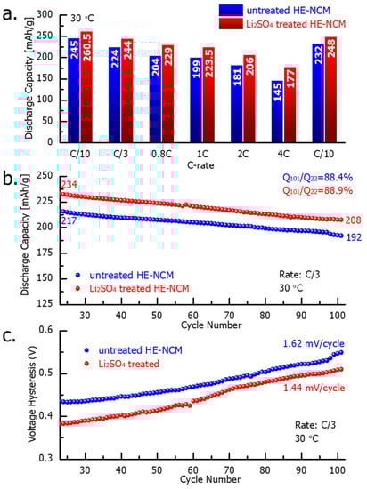
Figure 6.
Results of the electrochemical studies of HE-NCM electrodes comprising untreated and Li2SO4-treated HE-NCM materials, as indicated: (a) discharge capacity obtained at various current densities (C-rates); (b) prolonged cycling, and (c) the voltage hysteresis. Experiments were performed in coin-type cells with Li counter-electrodes, LP-57 solution, at 30 °C. Note that each experiment in this study was carried out for at least 2–3 cells simultaneously, and the results were averaged.
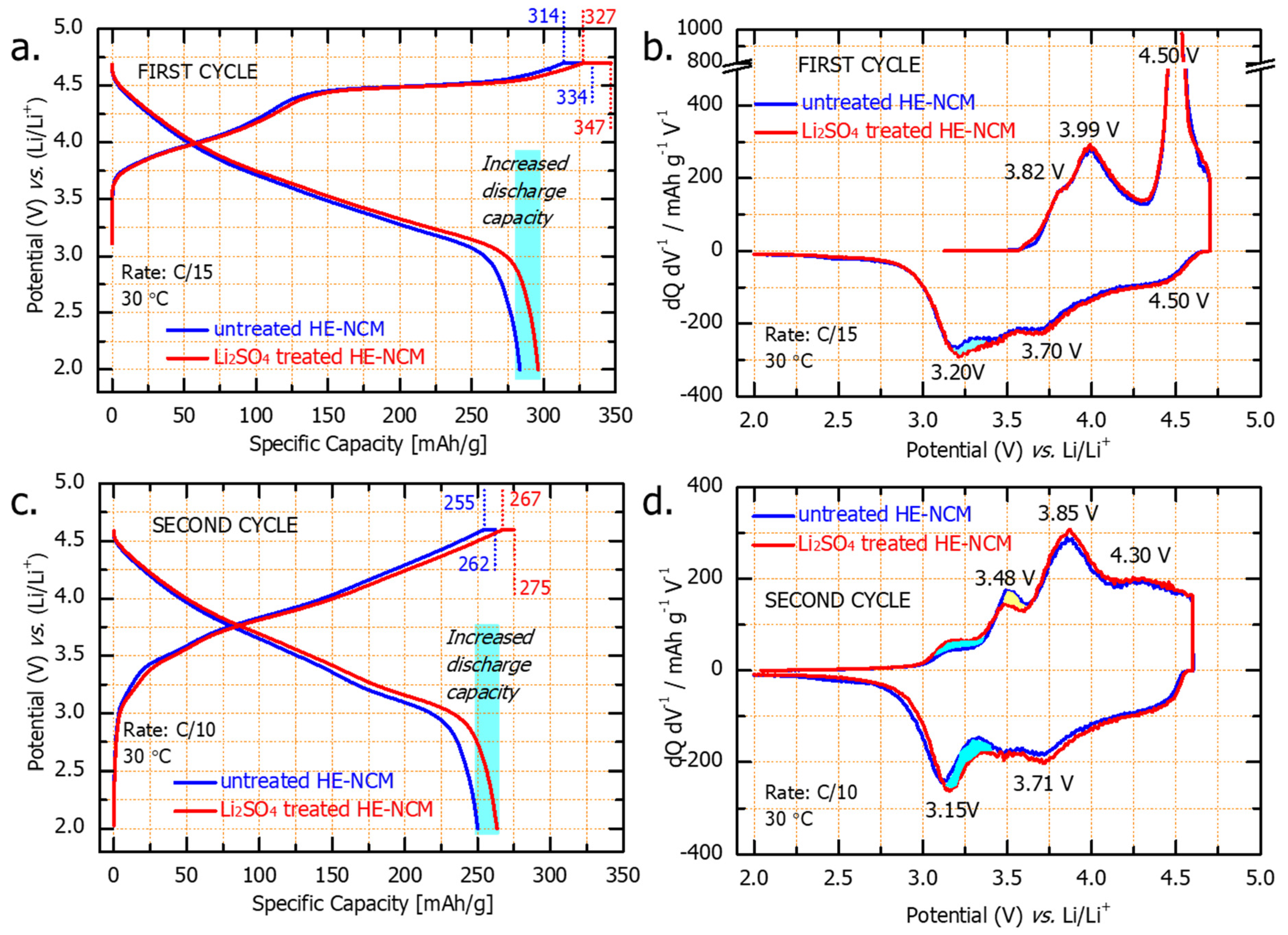
Figure 7a,c represent, respectively the first and second charge and discharge voltage profiles for untreated and Li2SO4-treated HE-NCM. They are typical for HE-NCM electrodes, as established in several literature reports [46,47]. The charge profiles consist of two parts: first, at potentials below 4.5 V, Li+ is extracted from the LiTMO2 component, concomitant with the oxidation of Ni2+/Ni4+ and Co3+/Co4+ in the transition metal layers [48]. The second part of the charge curve (above 4.5 V) exhibits the voltage plateau attributed to the activation of the Li2MnO3 component, which can be represented as follows [49,50]:
Li2MnO3 → 2Li+ + 2e− + MnO2 + 1/2O2↑
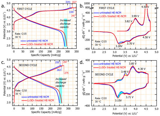
Figure 7.
Voltage profiles of the first (a) and second (c) cycles and the corresponding dQ/dV vs. V profiles (b,d) of untreated and Li2SO4treated HE-NCM cathodes (as indicated) tested in Li cells at 30 °C. Note that a constant voltage step for 3 h was applied at 4.7 V in the initial charge, while all subsequent constant voltage steps at 4.6 V were for 30 min. As a result, the capacities delivered were ~20 mAh/g and ~8 mAh/g, respectively, for the 1st and 2nd cycles, for both untreated and Li2SO4treated HE-NCM cathodes.
At the end of the first discharge (C/15 rate) of the Li2SO4-treated HE-NCM, we registered an additional capacity of ~20 mAh/g, marked in light blue in Figure 7. In the dQ/dV curves of the formation cycles (Figure 7b,d), there are two dominant oxidation peaks, one around 4.0 V and the other at 4.5 V, corresponding, respectively, to the first and second parts of the voltage profile. On the discharge (Li insertion), the dQ/dV curves display three reduction peaks: the first one at 4.5 V that involves O2−x reduction, a second peak at 3.7 V involves Ni and Co reduction, and the third peak at 3.2 V that is related to the reduction of Mn4+/3+ involving Li+ insertion [51]. The additional discharge capacity relates likely to the contribution from the Mn reduction at ~3.2 V.
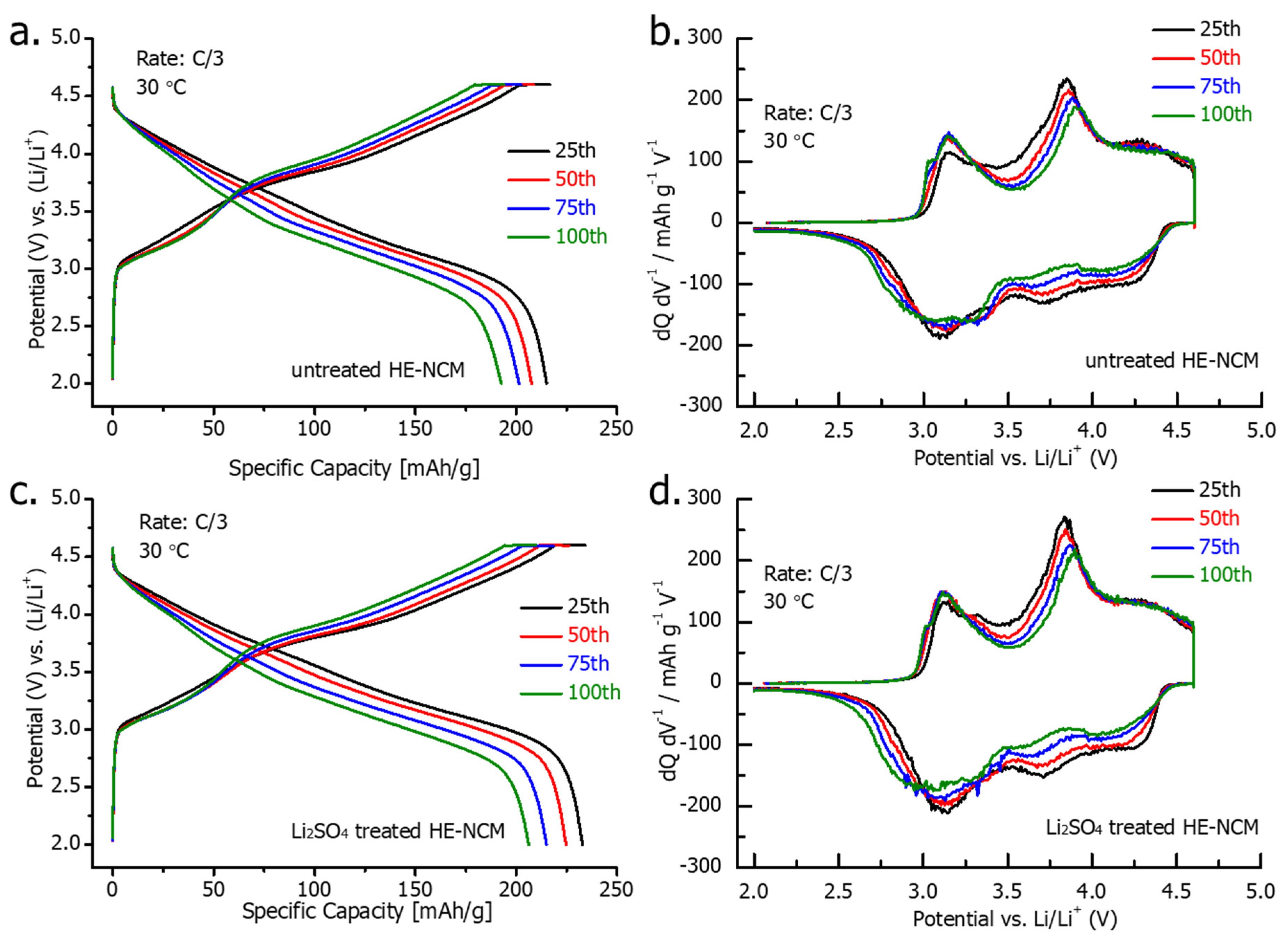
Voltage profiles and dQ/dV curves of the 25th-100th cycles at a C/3 rate are presented in Figure 8. They demonstrate a similar decline in the charge and discharge capacity during cycling (25th to 100th cycles) for both treated and untreated HE-NCM cathode materials. On the other hand, the results of the cycling performance in Figure 6b demonstrate that the higher capacity of the Li2SO4-treated HE-NCM is retained for 100 cycles. We suggest that this advantageous behavior of the treated material can be related to the stable electrode-solution interface modified with a thin nano-sized Li2SO4 layer that can react with traces of acidic species such as HF, PF5 (strong Lewis acid) in solution, thus protecting the active cathode mass—for instance [26]:
Li2MnO3(s) + PF5(sol) → 2LiF(s) + POF3(gas) + MnO2(s)
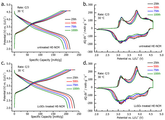
Figure 8.
Voltage profiles and dQ/dV vs. V plots, recorded at a C/3 rate from 25th, 50th, 75th, and 100th cycles for untreated (a,b) and Li2SO4treated (c,d) HE-NCM cathodes in Li cells at 30 °C.
The Li2SO4 coating can act as a buffer zone to react with the electrolyte solution and its decomposition species such as PF5, thus partially protecting the active cathode mass:
Li2SO4(s) + PF5(sol) → 2LiF(s) + POF3(gas) + SO3(s)
It is important to emphasize that TEM analysis of the cycled electrodes (Figure 9) revealed that this layer retained its structural characteristics upon prolonged charge–discharge cycling of Li2SO4-treated materials.

Figure 9.
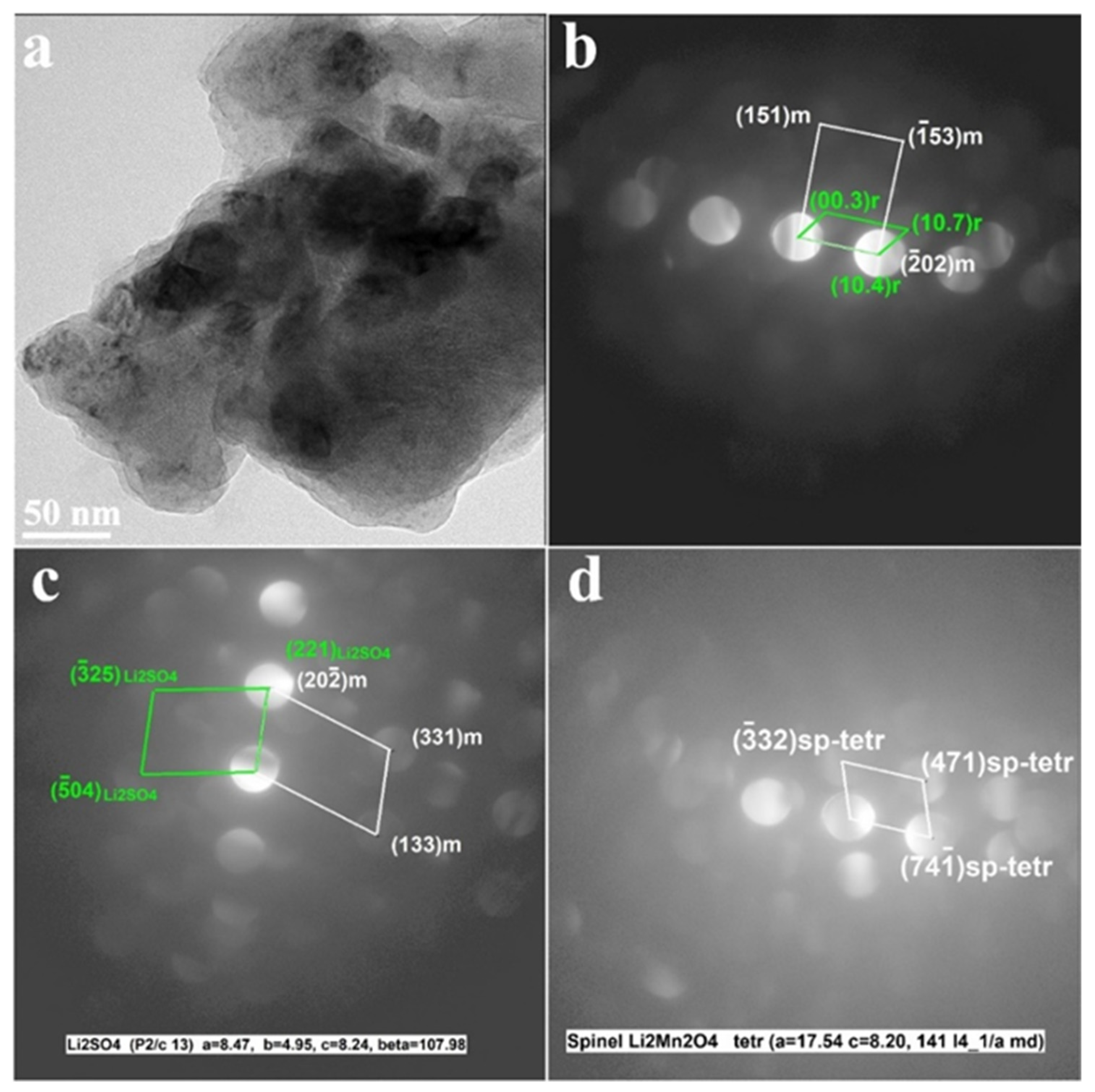
Results of the TEM studies of the Li2SO4-treated HE-NCM samples cycled in Li cells (after 101 cycles). (a) TEM images show agglomerated particles of cycled HE-NCM; (b–d) CBED patterns demonstrate the constituent rhombohedral (R-3m) and monoclinic (C2/m) phases of HE-NCM along with those of Li2SO4 (P21/c) and tetragonal spinel-type (marked sp-tetr) in Figure 9c,d, respectively. The latter was formed during cycling because of a partial layered-to-spinel structural transformation.
Figure 9 demonstrates that the CBED patterns of cycled electrodes contain reflections from the constituent rhombohedral Li(TM)O2 and monoclinic Li2MnO3 components along with the Li2SO4 phase (space group P21/c). They also show reflections of the tetragonal spinel, tentatively of the composition Li2Mn2O4 formed during cycling due to a partial layered-to-spinel structural transformation [52]. In fact, cubic spinel LiMn2O4 is usually formed, which converts into a tetragonal phase upon the discharging process by the insertion of Li+ ions [53].
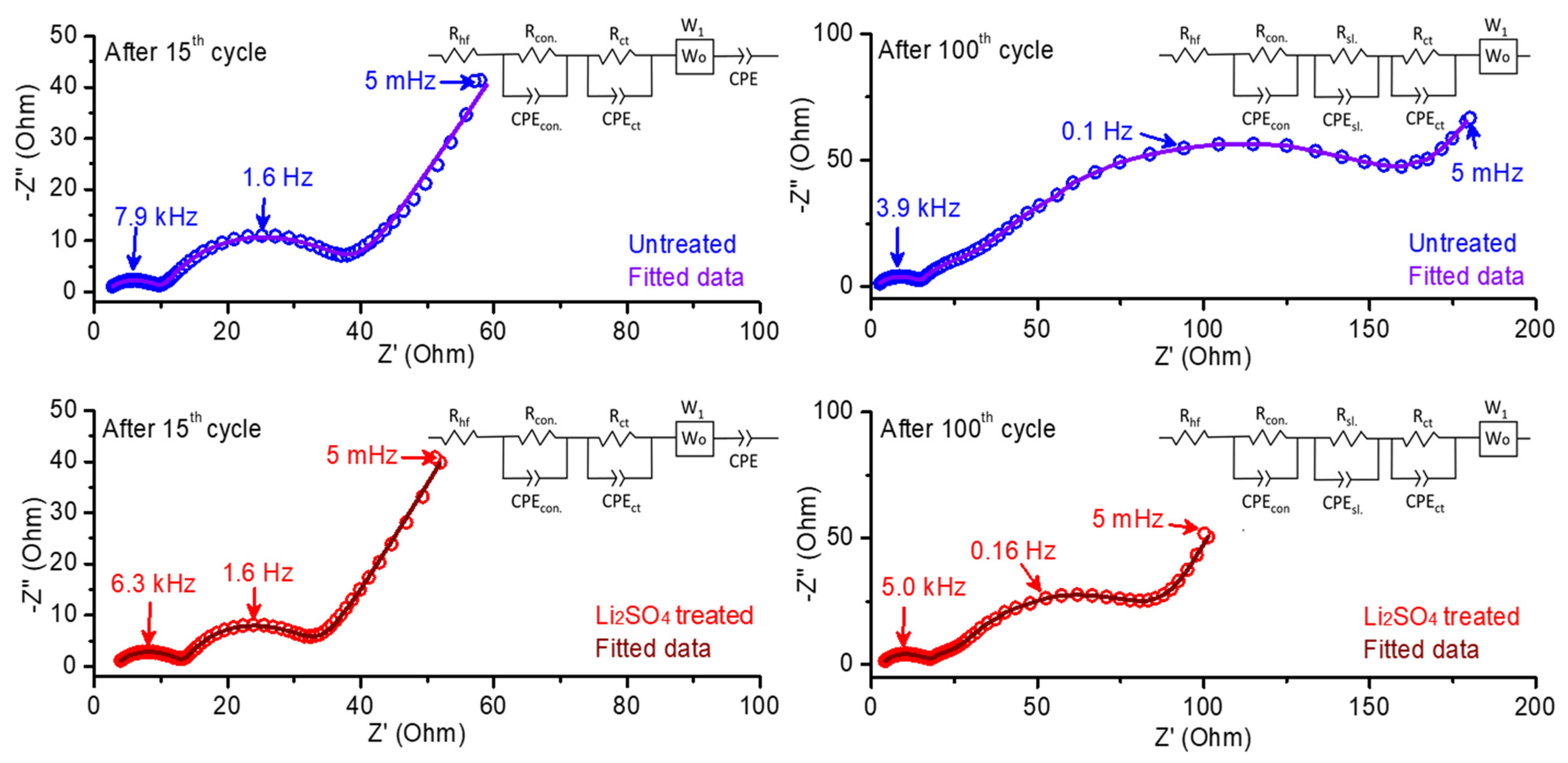
In Figure 10, we compare impedance spectra measured from electrodes comprising the untreated and Li2SO4-treated HE-NCM materials (in three-electrode cells with Li reference) after the 15th and 100th cycles at an equilibrium potential of 4.0 V during discharge. The observed Nyquist plots in this figure show the characteristic features typical for Li intercalation electrodes, namely two semicircles and a straight line. The first semicircle, which appears at high-to-medium frequencies, is due to the Li+-ion migration through electrode surface films. The second one at medium-to-low frequencies reflects interfacial charge-transfer processes, and the straight line at the low-frequency region represents the Warburg impedance (W), which is attributed to the resistance of the solid-state (bulk) diffusion of Li+ ions [54]. These impedance results were used further to analyze the reasons behind the stable and improved electrochemical cycling and rate performance for the Li2SO4-treated electrode material. We demonstrate in Figure 10 the experimental and fitted Nyquist plots of both treated and untreated electrode materials. The values of parameters (resistances and capacitances or constant phase elements, CPE) from fitted data and the corresponding equivalent circuit models are shown in Table 2 and Figure 10, respectively. From the results obtained, we conclude that the charge-transfer resistance Rct (calculated as the diameter of the second semicircle) decreased for the treated HE-NCM electrode compared to the untreated one after the 15th and 100th cycles. As expected, the total resistance for both the treated and untreated electrodes increased during the electrochemical cycling [55]. The Li2SO4-treated material showed relatively higher solution resistance (Rhf) and contact resistance (Rcon) than the untreated sample, as follows from Table 2. This phenomenon may be due to the presence of a Li2SO4 coating, which acts as an additional surface passivation layer. The lower resistance of the Li+ migration through the surface layer (Rsl) formed on the cathode was observed for the treated sample. However, both the cells comprising untreated and treated electrodes did not show much change in Rhf values after the 100th cycle compared to that after the 15th cycle. Typically, the cells comprising the Li2SO4-treated electrode material demonstrate lower charge-transfer resistances Rct of 14.4 Ω and 55.9 Ω than the untreated material (22.6 Ω and 137.7 Ω) after the 15th and 100th cycle, respectively. These observations allow us to conclude on the improved interfacial charge-transfer kinetics due to the presence of the nano-sized lithium sulfate surface layer formed upon thermal treatment of the HE-NCM and Li2SO4 mixture at 600 °C [56]. It is suggested that, at 575 °C, lithium sulfate underwent first-order phase transition from an ordered, low-symmetry (monoclinic), poorly conducting β-phase to a disordered, high-symmetry, high Li+-conducting α-phase that promotes the kinetics at the electrode–solution interface, while, upon cooling back to room temperature, a disordered β-phase was formed with higher conductivity properties [57].

Figure 10.
Experimental and fitted impedance spectra (Nyquist plots) of untreated and Li2SO4treated HE-NCM electrode materials after 15th and 100th cycles measured at 4.0 V during discharge at 30 °C. We carried out these measurements in three-electrode cells with Li reference electrodes in 1.0 M LiPF6/EC-EMC (3:7 v/v) solutions, at 30 °C. The equivalent circuit models are presented as insets in each plot.
Table 2.
Fitted data for impedance spectra measured from HE-NCM electrodes at 15th and 100th cycles at an equilibrium potential of 4.0 V during discharge. The corresponding impedance spectra of these cells are presented in Figure 10. In this table, Rhf, Rcon, Rsl, and Rct relate, respectively, to the solution resistance measured at high frequencies, the contact resistance of the cathode, the resistance of the Li+ migration through the surface layer formed on the cathode, and interfacial charge-transfer resistance, representing a contribution from both the electrodes (cathode and anode) in Li cells.
3.3. Gas Evolution from HE-NCM Electrodes Studied by OEMS
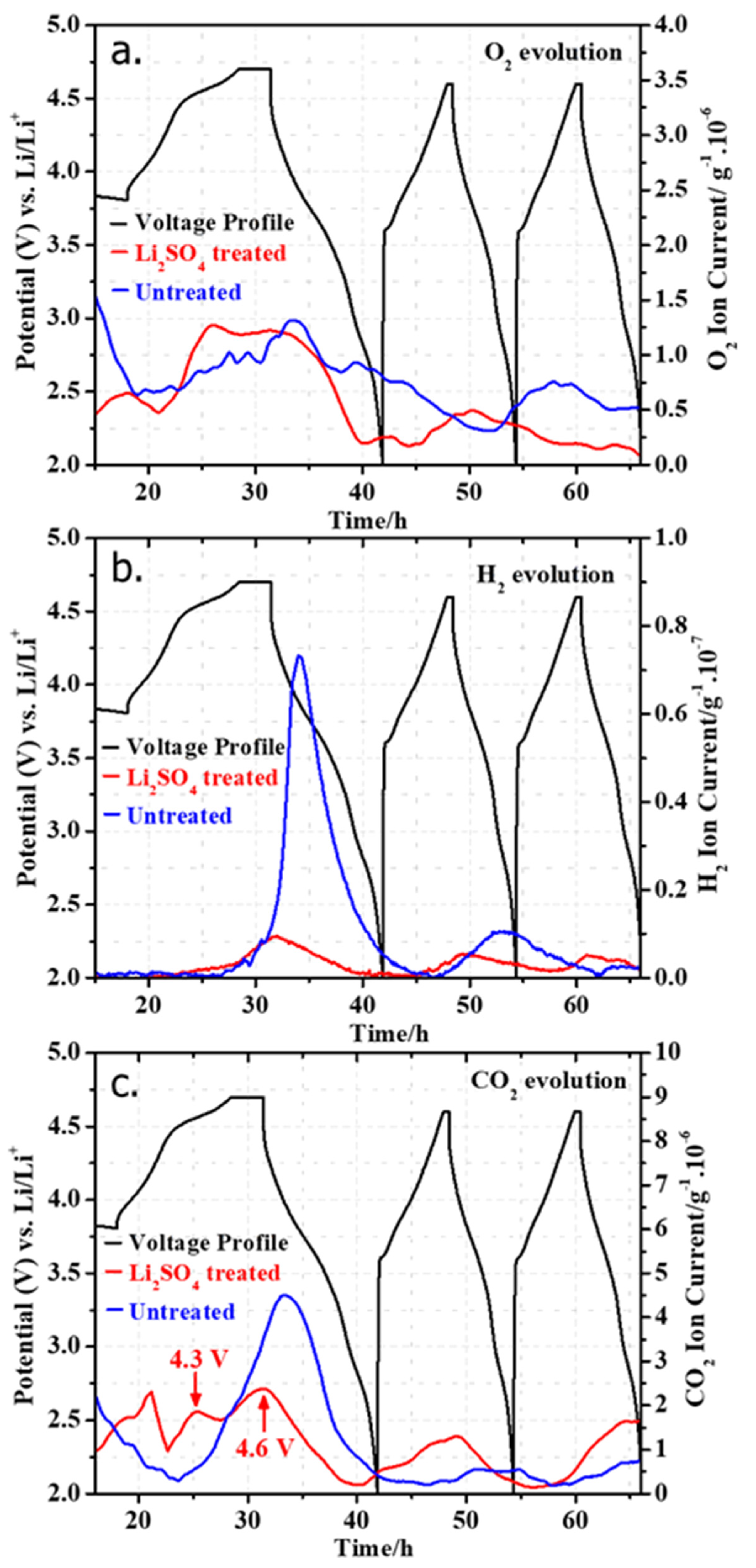
Figure 11 compares results of the O2 evolution registered with an onset potential close to the 4.5 V plateau during the first cycle of HE-NCM electrodes containing both the untreated and Li2SO4-treated samples. The onset of O2 was observed at ~4.5 V in the first charge, and oxygen evolution continued to increase until 3.6 V in the first discharge. Subsequently, the O2 evolution diminished during the discharge to 2.0 V. We note that the O2 evolution at 4.5 V is slightly higher (~1.3 × 10⁻⁶ g) for the Li2SO4-treated sample compared to the untreated one (~1.0 × 10⁻⁶ g), which can be related partly to more Li+ extracted and a higher charge capacity obtained in the first charge, as indicated in Figure 7a. It is important to emphasize that oxygen is released not from the bulk Li2MnO3, but irreversibly from a several-nm-thick near-surface layer of HE-NCM material, as established by Gasteiger et al. [58,59]. Upon charging to high potentials, O2 can be oxidized to per-oxo species (2O2− ↔ O22− + 2e−) and then released as oxygen gas [41,60]. A minor amount of O2 evolved was also observed during the second cycle. For the untreated HE-NCM, there was a small wave of O2 release during the third cycle. Concerning the CO2 evolution, two waves were observed in the case of the Li2SO4-treated sample with onsets at 4.3 V and 4.6 V, respectively. The initial low-intensity wave can be assigned to the decomposition of surface impurities (for instance, Li2CO3) formed during the manufacture of the HE-NCM material and storage. It is suggested by Berkes et al. [61] that lithium carbonate decomposes with the evolution of CO2 and singlet oxygen [1O2]:
2Li2CO3 → 4Li+ + e− + 2CO2 + 1O2

Figure 11.
Results of the online mass spectrometry studies during cycling of electrodes comprising untreated HE-NCM (blue) and Li2SO4treated materials (red), showing the evolution of (a) O2, (b) H2, and (c) CO2. These measurements were performed in half-cells with Li-foil anodes and 1.0 M LiPF6/EC-EMC (3:7 v/v) electrolyte solutions (LP57).
The latter reactive species can supposedly oxidize ethylene carbonate, releasing CO2 and CO [61]. In fact, less CO2 is evolved from the electrode comprising the Li2SO4treated sample compared to the untreated one (Figure 11c). This can be attributed to the nano-sized Li2SO4 layer, which effectively protected the HE-NCM material from further reactions with CO2 and H2O upon storage and electrode preparation [62]. As shown in Figure 11a,c, the second wave of CO2 originates in parallel to the O2 evolution, and it can be attributed to the electrolytic decomposition or the attack of reactive oxygen species on the ethylene carbonate. Significantly higher CO2 evolution from the untreated sample was seen, implying also that treatment of HE-NCM with Li2SO4 helped in suppressing the electrolyte degradation at high potentials. This may probably relate to much greater H2 evolution from the untreated sample than the Li2SO4-treated HE-NCM during the first discharge (Figure 11b). As discussed in the literature, the H2 evolution is due to H2O reduction from the anode side [63]. Metzger et al. suggested that the infiltration of water vapor through the sealing of the coin cell battery leads to the production of H2 and OH− upon H2O reduction at the lithium metal counter-electrode and results in the OH−-catalyzed hydrolysis of ethylene carbonate, yielding CO2 [63]. We observed no significant differences in gas evolution between the untreated and treated HE-NCM cathodes during further cycling. Thus, we can conclude that the main role of the Li2SO4 nano-sized layer for the gas evolution is on the initial cycle during activation of the HE-NCM material at 4.5 V.
3.4. Thermal Stability of HE-NCM Materials in Battery Solutions: DSC Studies
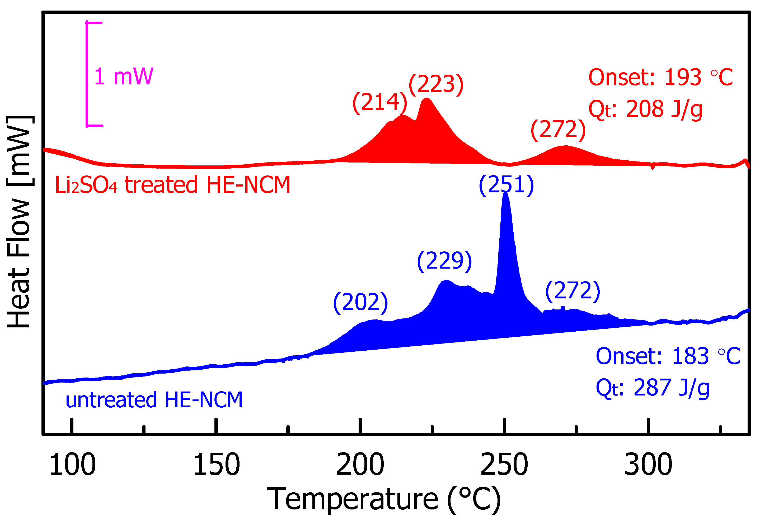
Figure 12 represents the results of DSC measurements, which aimed to compare the thermal stability of the untreated and Li2SO4treated HE-NCM materials in 1.0 M LiPF6/EC-EMC (3:7 v/v) electrolyte solution. Typical DSC profiles demonstrate four major exothermic peaks at ~202, ~229, ~251, and ~272 °C, registered for the untreated material. These peaks reflect thermochemical interactions between oxygen released from the HE-NCM lattice and the EC, EMC solvents in the solution upon release of H2O/CO2, as reported in [64]. These reactions involve lattice oxygen loss and partial lithium leaching in the form of Li2O [64]. The onset temperatures of the above exothermic reactions were found to be 183 and 193 °C for untreated and Li2SO4treated HE-NCM materials, respectively, implying thus that the Li2SO4 coating suppresses the heat evolution partially at a lower temperature. The temperature zones at 202 and 229 °C are typically linked to the reactions between the released lattice oxygen and solvents [64], while the heat evolution at 251 and 272 °C relates to solvent molecules’ combustion reactions with HE-NCM materials [65]. We calculated the specific total heat release for the untreated and Li2SO4-treated materials to be 287 and 208 J/g, respectively. It allows us to conclude that the artificial nanometer-sized Li2SO4 surface layer on the HE-NCM material most likely inhibits interactions of the lattice oxygen with the solvent molecules, reducing thus the heat evolution by ~28%.

Figure 12.
Results of the DSC measurements of untreated and Li2SO4-treated HE-NCM pristine materials (powders) in 1.0 M LiPF6/EC-EMC (3:7 v/v) electrolyte solution (LP57).
4. Conclusions
In this work, we have established the advantageous electrochemical performance and improved thermal behavior of HE-NCM materials modified with nano-sized lithium sulfate. We summarize the conclusions as follows:
- A few-nanometer-thick crystalline Li2SO4 layer was formed on the material’s surface (for example, 0.35Li2MnO3.0.65LiNi0.35Mn0.45Co0.20O2) by direct and simple mixing with lithium sulfate and further annealing at 600 °C.
- From the analysis of the electrochemical data, we concluded that cathodes comprising these Li2SO4-modified materials exhibited ~20% higher discharge capacity, two-times lower charge-transfer resistance, resulting in faster kinetics, and higher capacity at various cycling rates.
- We suggest that the smooth nano-sized Li2SO4 surface layer provided mitigation of the interfacial side reactions at high anodic potentials while retaining the structural integrity of the cathode materials upon cycling in Li cells. Furthermore, we established that an additional phase, likely tetragonal spinel Li2Mn2O4, was formed during the cycling of HE-NCM cathodes due to a partial layered-to-spinel structural transformation, in agreement with the literature reports.
- A significant conclusion of this work is that the thermal stability (measured by DSC as the total heat evolution) of the Li2SO4-treated samples in reactions with EC-EMC/LiPF6 solutions decreased by ~28%. This is likely due to the artificial nano-sized Li2SO4 surface layer on the HE-NCM material, which inhibits interactions of the lattice oxygen with the solvent molecules, thus reducing heat evolution.
- We can also conclude that the Li2SO4 layer partially suppressed the electrolyte degradation during the first formation charge–discharge cycle of HE-NCM cathodes. This follows from the significantly lower CO2 and H2 gas evolution in the Li2SO4-treated samples shown by online electrochemical mass spectrometry tests.
- An important finding of this work is that the Li2SO4 phase remained on the surface of the HE-NCM cathodes and preserved its structural characteristics (space group P21/c) after 100 charge–discharge cycles.
- We propose that direct chemical treatment with nano-sized Li2SO4 for stabilizing highly reactive HE-NCM cathode materials can help to realize high-energy-density Li-ion battery systems.
Author Contributions
Conceptualization, H.S. and B.M.; methodology, E.M.E. and S.M.; software, H.S. and S.M.; formal analysis, H.S., S.M., R.S. and R.R.; investigation, H.S., M.N., S.M. and R.S.; data curation, J.G., M.T. and B.M.; writing—original draft preparation, H.S. and S.M.; writing—review and editing, B.M., J.G., M.T., D.A. and A.K.; visualization, D.A. and B.M.; supervision, D.A.; project administration, A.K. and D.A. All authors have read and agreed to the published version of the manuscript.
Funding
This research received partial funding from BASF SE, Germany.
Institutional Review Board Statement
Not applicable.
Informed Consent Statement
Not applicable.
Data Availability Statement
Available on request.
Acknowledgments
This research was supported in part by BASF SE, Germany, by the Israeli Prime Minister’s Office, and by the Israeli Committee for Higher Education within the framework of the INREP project.
Conflicts of Interest
The authors declare no conflict of interest.
References
- Thackeray, M.M.; Johnson, C.S.; Vaughey, J.T.; Li, N.; Hackney, S.A. Advances in Manganese-Oxide ‘Composite’ Electrodes for Lithium-Ion Batteries. J. Mater. Chem. 2005, 15, 2257. [Google Scholar] [CrossRef]
- Thackeray, M.M.; Kang, S.-H.; Johnson, C.S.; Vaughey, J.T.; Benedek, R.; Hackney, S.A. Li2MnO3-Stabilized LiMO2 (M = Mn, Ni, Co) Electrodes for Lithium-Ion Batteries. J. Mater. Chem. 2007, 17, 3112. [Google Scholar] [CrossRef]
- Nayak, P.K.; Erickson, E.M.; Schipper, F.; Penki, T.R.; Munichandraiah, N.; Adelhelm, P.; Sclar, H.; Amalraj, F.; Markovsky, B.; Aurbach, D. Review on Challenges and Recent Advances in the Electrochemical Performance of High Capacity Li- and Mn-Rich Cathode Materials for Li-Ion Batteries. Adv. Energy Mater. 2018, 8, 1702397. [Google Scholar] [CrossRef]
- Jung, R.; Metzger, M.; Maglia, F.; Stinner, C.; Gasteiger, H.A. Oxygen Release and Its Effect on the Cycling Stability of LiNixMnyCozO2 (NMC) Cathode Materials for Li-Ion Batteries. J. Electrochem. Soc. 2017, 164, A1361–A1377. [Google Scholar] [CrossRef]
- Johnson, C.S.; Li, N.; Lefief, C.; Vaughey, J.T.; Thackeray, M.M. Synthesis, Characterization and Electrochemistry of Lithium Battery Electrodes: X Li 2 MnO 3 ·(1 − x )LiMn 0.333 Ni 0.333 Co 0.333 O 2 (0 ≤ x ≤ 0.7). Chem. Mater. 2008, 20, 6095–6106. [Google Scholar] [CrossRef]
- Zheng, J.; Myeong, S.; Cho, W.; Yan, P.; Xiao, J.; Wang, C.; Cho, J.; Zhang, J. Li- and Mn-Rich Cathode Materials: Challenges to Commercialization. Adv. Energy Mater. 2017, 7, 1601284. [Google Scholar] [CrossRef]
- Chen, G.; An, J.; Meng, Y.; Yuan, C.; Matthews, B.; Dou, F.; Shi, L.; Zhou, Y.; Song, P.; Wu, G.; et al. Cation and Anion Co-Doping Synergy to Improve Structural Stability of Li- and Mn-Rich Layered Cathode Materials for Lithium-Ion Batteries. Nano Energy 2019, 57, 157–165. [Google Scholar] [CrossRef]
- He, W.; Liu, P.; Qu, B.; Zheng, Z.; Zheng, H.; Deng, P.; Li, P. Uniform Na+ Doping-Induced Defects in Li- and Mn-Rich Cathodes for High-Performance Lithium-Ion Batteries. Adv. Sci. 2019, 6, 1802114. [Google Scholar] [CrossRef] [Green Version]
- Nayak, P.K.; Grinblat, J.; Levi, M.; Levi, E.; Kim, S.; Choi, J.W.; Aurbach, D. Al Doping for Mitigating the Capacity Fading and Voltage Decay of Layered Li and Mn-Rich Cathodes for Li-Ion Batteries. Adv. Energy Mater. 2016, 6, 1–13. [Google Scholar] [CrossRef]
- Liu, D.; Fan, X.; Li, Z.; Liu, T.; Sun, M.; Qian, C.; Ling, M.; Liu, Y.; Liang, C. A Cation/Anion Co-Doped Li1.12Na0.08Ni0.2Mn0.6O1.95F0.05 Cathode for Lithium Ion Batteries. Nano Energy 2019, 58, 786–796. [Google Scholar] [CrossRef]
- Phattharasupakun, N.; Geng, C.; Johnson, M.B.; Väli, R.; Sawangphruk, M.; Dahn, J.R. Impact of Cr Doping on the Voltage Fade of Li-Rich Mn-Rich Li1.11Ni0.33Mn0.56O2 and Li1.2Ni0.2Mn0.6O2 Positive Electrode Materials. J. Electrochem. Soc. 2020, 167, 160545. [Google Scholar] [CrossRef]
- Seok Jung, Y.; Cavanagh, A.S.; Yan, Y.; George, S.M.; Manthiram, A. Effects of Atomic Layer Deposition of Al2O3 on the Li[Li0.20Mn0.54Ni0.13Co0.13]O2 Cathode for Lithium-Ion Batteries. J. Electrochem. Soc. 2011, 158, A1298. [Google Scholar] [CrossRef]
- Lei, Y.; Ni, J.; Hu, Z.; Wang, Z.; Gui, F.; Li, B.; Ming, P.; Zhang, C.; Elias, Y.; Aurbach, D.; et al. Surface Modification of Li-Rich Mn-Based Layered Oxide Cathodes: Challenges, Materials, Methods, and Characterization. Adv. Energy Mater. 2020, 10, 2002506. [Google Scholar] [CrossRef]
- Bettge, M.; Li, Y.; Sankaran, B.; Rago, N.D.; Spila, T.; Haasch, R.T.; Petrov, I.; Abraham, D.P. Improving High-Capacity Li1.2Ni 0.15 Mn0.55Co0.1O2-Based Lithium-Ion Cells by Modifiying the Positive Electrode with Alumina. J. Power Sources 2013, 233, 346–357. [Google Scholar] [CrossRef]
- Zou, G.; Yang, X.; Wang, X.; Ge, L.; Shu, H.; Bai, Y.; Wu, C.; Guo, H.; Hu, L.; Yi, X.; et al. Improvement of Electrochemical Performance for Li-Rich Spherical Li1.3[Ni0.35 Mn0.65 ]O2+x Modified by Al2O3. J. Solid State Electrochem. 2014, 18, 1789–1797. [Google Scholar] [CrossRef]
- Zhang, X.; Belharouak, I.; Li, L.; Lei, Y.; Elam, J.W.; Nie, A.; Chen, X.; Yassar, R.S.; Axelbaum, R.L. Structural and Electrochemical Study of Al2O3 and TiO2 Coated Li1.2Ni0.13Mn0.54Co0.13O = Cathode Material Using ALD. Adv. Energy Mater. 2013, 3, 1299–1307. [Google Scholar] [CrossRef]
- Gao, Y.; Patel, R.L.; Shen, K.-Y.; Wang, X.; Axelbaum, R.L.; Liang, X. Boosting the Electrochemical Performance of Li1.2Mn0.54Ni0.13Co0.13O2 by Atomic Layer-Deposited CeO2Coating. ACS Omega 2018, 3, 906–916. [Google Scholar] [CrossRef] [PubMed] [Green Version]
- Xiao, B.; Wang, B.; Liu, J.; Kaliyappan, K.; Sun, Q.; Liu, Y.; Dadheech, G.; Balogh, M.P.; Yang, L.; Sham, T.-K.; et al. Highly Stable Li1.2Mn0.54Co0.13Ni0.13O2Enabled by Novel Atomic Layer Deposited AlPO4 Coating. Nano Energy 2017, 34, 120–130. [Google Scholar] [CrossRef]
- Amalraj, F.; Talianker, M.; Markovsky, B.; Burlaka, L.; Leifer, N.; Goobes, G.; Erickson, E.M.; Haik, O.; Grinblat, J.; Zinigrad, E.; et al. Studies of Li and Mn-Rich Lix[MnNiCo]O2Electrodes: Electrochemical Performance, Structure, and the Effect of the Aluminum Fluoride Coating. J. Electrochem. Soc. 2013, 160, A2220–A2233. [Google Scholar] [CrossRef]
- Maiti, S.; Sclar, H.; Sharma, R.; Vishkin, N.; Fayena-Greenstein, M.; Grinblat, J.; Talianker, M.; Burstein, L.; Solomatin, N.; Tiurin, O.; et al. Understanding the Role of Alumina (Al2O3), Pentalithium Aluminate (Li5AlO4), and Pentasodium Aluminate (Na5AlO4) Coatings on the Li and Mn-Rich NCM Cathode Material 0.33Li2MnO3·0.67Li(Ni0.4Co0.2Mn0.4)O2 for Enhanced Electrochemical Performance. Adv. Funct. Mater. 2020, 31, 2008083. [Google Scholar] [CrossRef]
- Sclar, H.; Maiti, S.; Leifer, N.; Vishkin, N.; Fayena-Greenstein, M.; Hen, M.; Grinblat, J.; Talianker, M.; Solomatin, N.; Tiurin, O.; et al. Electrochemical and Thermal Behavior of Modified Li and Mn-Rich Cathode Materials in Battery Prototypes: Impact of Pentasodium Aluminate Coating and Comprehensive Understanding of Its Evolution upon Cycling through Solid-State Nuclear Magnetic Resonance A. Adv. Energy Sustain. Res. 2021, 2, 2000089. [Google Scholar] [CrossRef]
- Erickson, E.M.; Sclar, H.; Schipper, F.; Liu, J.; Tian, R.; Ghanty, C.; Burstein, L.; Leifer, N.; Grinblat, J.; Talianker, M.; et al. High-Temperature Treatment of Li-Rich Cathode Materials with Ammonia: Improved Capacity and Mean Voltage Stability during Cycling. Adv. Energy Mater. 2017, 7, 1700708. [Google Scholar] [CrossRef]
- Breddemann, U.; Erickson, E.M.; Davis, V.; Schipper, F.; Ellwanger, M.; Daub, M.; Hoffmann, A.; Erk, C.; Markovsky, B.; Aurbach, D.; et al. Fluorination of Li-Rich Lithium-Ion-Battery Cathode Materials by Fluorine Gas: Chemistry, Characterization, and Electrochemical Performance in Half Cells. ChemElectroChem 2019, 6, 3337–3349. [Google Scholar] [CrossRef]
- Ueda, M.; Ohe, M.; Kim, J.-H.; Yonezawa, S.; Takashima, M. Effects of Surface Fluorination on the Electrochemical Properties and Thermal Stability of LiFePO4 Cathode for Lithium-Ion Batteries. J. Fluor. Chem. 2013, 149, 88–94. [Google Scholar] [CrossRef]
- Qiu, B.; Zhang, M.; Wu, L.; Wang, J.; Xia, Y.; Qian, D.; Liu, H.; Hy, S.; Chen, Y.; An, K.; et al. Gas–Solid Interfacial Modification of Oxygen Activity in Layered Oxide Cathodes for Lithium-Ion Batteries. Nat. Commun. 2016, 7, 12108. [Google Scholar] [CrossRef]
- Susai, F.A.; Sclar, H.; Maiti, S.; Burstein, L.; Perkal, O.; Grinblat, J.; Talianker, M.; Ruthstein, S.; Erk, C.; Hartmann, P.; et al. Stabilized Behavior of LiNi0.85Co0.10Mn0.05O2Cathode Materials Induced by Their Treatment with SO2. ACS Appl. Energy Mater. 2020, 3, 3609–3618. [Google Scholar] [CrossRef]
- Sclar, H.; Sicklinger, J.; Erickson, E.M.; Maiti, S.; Grinblat, J.; Talianker, M.; Amalraj Susai, F.; Burstein, L.; Beyer, H.; Hartmann, L.; et al. Enhancement of Electrochemical Performance of Lithium and Manganese-Rich Cathode Materials via Thermal Treatment with SO2. J. Electrochem. Soc. 2020, 167, 110563. [Google Scholar] [CrossRef]
- Zhang, S.S.; Chen, J.; Wang, C. Elemental Sulfur as a Cathode Additive for Enhanced Rate Capability of Layered Lithium Transition Metal Oxides. J. Electrochem. Soc. 2019, 166, A487–A492. [Google Scholar] [CrossRef] [Green Version]
- Pan, X.; Zeng, Y.; Gao, Z.; Xie, S.; Xiao, F.; Liu, L. Effects of Li2SO4·H2O Amounts on Morphologies of Hydrothermal Synthesized LiMnPO4Cathodes. RSC Adv. 2016, 6, 103232–103237. [Google Scholar] [CrossRef]
- Lv, D.; Wang, L.; Hu, P.; Sun, Z.; Chen, Z.; Zhang, Q.; Cheng, W.; Ren, W.; Bian, L.; Xu, J.; et al. Li2O-B2O3-Li2SO4 Modified LiNi1/3Co1/3Mn1/3O2 Cathode Material for Enhanced Electrochemical Performance. Electrochim. Acta 2017, 247, 803–811. [Google Scholar] [CrossRef]
- Nagao, K.; Hayashi, A.; Deguchi, M.; Tsukasaki, H.; Mori, S.; Tatsumisago, M. Amorphous LiCoO2Li2SO4 Active Materials: Potential Positive Electrodes for Bulk-Type All-Oxide Solid-State Lithium Batteries with High Energy Density. J. Power Sources 2017, 348, 1–8. [Google Scholar] [CrossRef]
- Savina, A.; Orlova, E.; Morozov, A.; Luchkin, S.; Abakumov, A. Sulfate-Containing Composite Based on Ni-Rich Layered Oxide LiNi0.8Mn0.1Co0.1O2 as High-Performance Cathode Material for Li-Ion Batteries. Nanomaterials 2020, 10, 2381. [Google Scholar] [CrossRef] [PubMed]
- Young, R.A.; Wiles, D.B. Profile Shape Functions in Rietveld Refinements. J. Appl. Crystallogr. 1982, 15, 430–438. [Google Scholar] [CrossRef]
- Caglioti, G.; Paoletti, A.; Ricci, F.P. Choice of Collimators for a Crystal Spectrometer for Neutron Diffraction. Nucl. Instrum. 1958, 3, 223–228. [Google Scholar] [CrossRef]
- Rosy; Sclar, H.; Evenstein, E.; Haber, S.; Maiti, S.; Sharabani, T.; Leskes, M.; Noked, M. Mitigating Structural Instability of High-Energy Lithium- and Manganese-Rich LiNixMnyCoz Oxide by Interfacial Atomic Surface Reduction. Chem. Mater. 2019, 31, 3840–3847. [Google Scholar] [CrossRef]
- GAS CHROMATOGRAPHY-DIFFERENTIAL ELECTROCHEMICAL MASS SPECTROMETRY (GC-DEMS). Available online: https://www.hidenanalytical.com/products/gas-analysis/hpr-40-dems/ (accessed on 28 February 2022).
- Peng, L.; Zhu, Y.; Khakoo, U.; Chen, D.; Yu, G. Self-Assembled LiNi1/3Co1/3Mn1/3O2 Nanosheet Cathodes with Tunable Rate Capability. Nano Energy 2015, 17, 36–42. [Google Scholar] [CrossRef]
- Croy, J.R.; Gallagher, K.G.; Balasubramanian, M.; Long, B.R.; Thackeray, M.M. Quantifying Hysteresis and Voltage Fade in XLi2MnO3(1-x)LiMn0.5Ni0.5O2Electrodes as a Function of Li2MnO3Content. J. Electrochem. Soc. 2014, 161, A318–A325. [Google Scholar] [CrossRef]
- Rama Rao, S.; Bheema Lingam, C.; Rajesh, D.; Vijayalakshmi, R.P.; Sunandana, C.S. Structural, Conductivity and Dielectric Properties of Li2SO4. Eur. Phys. J. Appl. Phys. 2014, 66, 30906. [Google Scholar] [CrossRef]
- Varghese, S.; Hariharan, K. Influence of Quenching on the Structural and Conduction Characteristics of Lithium Sulfate. Ionics 2018, 24, 2591–2599. [Google Scholar] [CrossRef]
- Assat, G.; Iadecola, A.; Foix, D.; Dedryvère, R.; Tarascan, J.-M. Direct Quantification of Anionic Redox over Long Cycling of Li-Rich NMC via Hard X-ray Photoemission Spectroscopy. ACS Energy Lett. 2018, 3, 2721–2728. [Google Scholar] [CrossRef]
- Andreu, N.; Flahaut, D.; Dedryvère, R.; Minvielle, M.; Martinez, H.; Gonbeau, D. XPS Investigation of Surface Reactivity of Electrode Materials: Effect of the Transition Metal. ACS Appl. Mater. Interfaces 2015, 7, 6629–6636. [Google Scholar] [CrossRef] [PubMed]
- Baggetto, L.; Dudney, N.J.; Veith, G.M. Surface Chemistry of Metal Oxide Coated Lithium Manganese Nickel Oxide Thin Film Cathodes Studied by XPS. Electrochim. Acta 2013, 90, 135–147. [Google Scholar] [CrossRef]
- Fantauzzi, M.; Elsener, B.; Atzei, D.; Rigoldi, A.; Rossi, A. Exploiting XPS for the Identification of Sulfides and Polysulfides. RSC Adv. 2015, 5, 75953–75963. [Google Scholar] [CrossRef]
- Biesinger, M.C.; Payne, B.P.; Grosvenor, A.P.; Lau, L.W.M.; Gerson, A.R.; Smart, R.S.C. Resolving Surface Chemical States in XPS Analysis of First Row Transition Metals, Oxides and Hydroxides: Cr, Mn, Fe, Co and Ni. Appl. Surf. Sci. 2011, 257, 2717–2730. [Google Scholar] [CrossRef]
- Rinaldo, S.G.; Gallagher, K.G.; Long, B.R.; Croy, J.R.; Bettge, M.; Dees, D.W.; Abraham, D.P.; Bare, J. Physical Theory of Voltage Fade in Lithium- and Manganese-Rich Transition Metal Oxides. 2015, 162 (6). J. Electrochem. Soc. 2015, 162, A897. [Google Scholar] [CrossRef] [Green Version]
- Wu, Y.; Xie, L.; He, X.; Zhuo, L.; Wang, L.; Ming, J. Electrochemical Activation, Voltage Decay and Hysteresis of Li-Rich Layered Cathode Probed by Various Cobalt Content. Electrochim. Acta 2018, 265, 115–120. [Google Scholar] [CrossRef] [Green Version]
- Lu, Z.; MacNeil, D.D.; Dahn, J.R. Layered Cathode Materials Li[NixLi1/3 − 2x/3Mn2/3−x/3O2 for Lithium-Ion Batteries. Electrochem. Solid-State Lett. 2001, 4, A191. [Google Scholar] [CrossRef]
- Teufl, T.; Strehle, B.; Müller, P.; Gasteiger, H.A.; Mendez, M.A. Oxygen Release and Surface Degradation of Li- and Mn-Rich Layered Oxides in Variation of the Li2MnO3Content. J. Electrochem. Soc. 2018, 165, A2718–A2731. [Google Scholar] [CrossRef] [Green Version]
- Lee, E.; Persson, K.A. Structural and Chemical Evolution of the Layered Li-Excess LixMnO3 as a Function of Li Content from First-Principles Calculations. Adv. Energy Mater. 2014, 4, 1400498. [Google Scholar] [CrossRef] [Green Version]
- Mohanty, D.; Kalnaus, S.; Meisner, R.A.; Rhodes, K.J.; Li, J.; Payzant, E.A.; Wood, D.L.; Daniel, C. Structural Transformation of a Lithium-Rich Li1.2Co0.1Mn0.55Ni0.15O2 Cathode during High Voltage Cycling Resolved by in Situ X-ray Diffraction. J. Power Sources 2013, 229, 239–248. [Google Scholar] [CrossRef]
- Amalraj, S.F.; Sharon, D.; Talianker, M.; Julien, C.M.; Burlaka, L.; Lavi, R.; Zhecheva, E.; Markovsky, B.; Zinigrad, E.; Kovacheva, D.; et al. Study of the Nanosized Li2MnO3: Electrochemical Behavior, Structure, Magnetic Properties, and Vibrational Modes. Electrochim. Acta 2013, 97, 259–270. [Google Scholar] [CrossRef]
- Susai, F.A.; Talianker, M.; Liu, J.; Rosy; Paul, T.; Grinblat, Y.; Erickson, E.; Noked, M.; Burstein, L.; Frenkel, A.I.; et al. Electrochemical Activation of Li2MnO3 Electrodes at 0 °C and Its Impact on the Subsequent Performance at Higher Temperatures. Materials 2020, 13, 4388. [Google Scholar] [CrossRef] [PubMed]
- Zheng, J.; Shi, W.; Gu, M.; Xiao, J.; Zuo, P.; Wang, C.; Zhang, J.-G. Electrochemical Kinetics and Performance of Layered Composite Cathode Material Li[Li0.2Ni0.2Mn0.6]O2. J. Electrochem. Soc. 2013, 160, A2212–A2219. [Google Scholar] [CrossRef]
- Lu, X.; Li, X.; Wang, Z.; Guo, H.; Yan, G.; Yin, X. A Modified Co-Precipitation Process to Coat LiNi1/3Co1/3Mn1/3O2 onto LiNi0.8Co0.1Mn0.1O2 for Improving the Electrochemical Performance. Appl. Surf. Sci. 2014, 297, 182–187. [Google Scholar] [CrossRef]
- Tarneberg, R. Ion Diffusion in the High-Temperature Phases Li2SO4, LiNaSO4, LiAgSO4 and Li4Zn(SO4)3. Solid State Ionics 1996, 90, 209–220. [Google Scholar] [CrossRef]
- Nord, A.G. Crystal Structure of β-Li2SO4. Acta Crystallogr. Sect. B Struct. Crystallogr. Cryst. Chem. 1976, 32, 982–983. [Google Scholar] [CrossRef] [Green Version]
- Kleiner, K.; Strehle, B.; Baker, A.R.; Day, S.J.; Tang, C.C.; Buchberger, I.; Chesneau, F.-F.; Gasteiger, H.A.; Piana, M. Origin of High Capacity and Poor Cycling Stability of Li-Rich Layered Oxides: A Long-Duration in Situ Synchrotron Powder Diffraction Study. Chem. Mater. 2018, 30, 3656–3667. [Google Scholar] [CrossRef]
- Strehle, B.; Kleiner, K.; Jung, R.; Chesneau, F.; Mendez, M.; Gasteiger, H.A.; Piana, M. The Role of Oxygen Release from Li- and Mn-Rich Layered Oxides during the First Cycles Investigated by On-Line Electrochemical Mass Spectrometry. J. Electrochem. Soc. 2017, 164, A400–A406. [Google Scholar] [CrossRef]
- Muhammad, S.; Kim, H.; Kim, Y.; Kim, D.; Song, J.H.; Yoon, J.; Park, J.; Ahn, S.; Kang, S.; Thackeray, M.M.; et al. Evidence of Reversible Oxygen Participation in Anomalously High Capacity Li- and Mn-Rich Cathodes for Li-Ion Batteries. Nano Energy 2016, 21, 172–184. [Google Scholar] [CrossRef] [Green Version]
- Rowden, B.; Garcia-Araez, N. A Review of Gas Evolution in Lithium Ion Batteries. Energy Rep. 2020, 6, 10–18. [Google Scholar] [CrossRef]
- Sicklinger, J.; Beyer, H.; Hartmann, L.; Riewald, F.; Sedlmeier, C.; Gasteiger, H.A. SO3Treatment of Lithium- and Manganese-Rich NCMs for Li-Ion Batteries: Enhanced Robustness towards Humid Ambient Air and Improved Full-Cell Performance. J. Electrochem. Soc. 2020, 167, 130507. [Google Scholar] [CrossRef]
- Metzger, M.; Strehle, B.; Solchenbach, S.; Gasteiger, H.A. Origin of H2Evolution in LIBs: H2O Reduction vs. Electrolyte Oxidation. J. Electrochem. Soc. 2016, 163, A798–A809. [Google Scholar] [CrossRef]
- Inoue, T.; Mukai, K. Are All-Solid-State Lithium-Ion Batteries Really Safe?–Verification by Differential Scanning Calorimetry with an All-Inclusive Microcell. ACS Appl. Mater. Interfaces 2017, 9, 1507–1515. [Google Scholar] [CrossRef] [PubMed]
- Haik, O.; Amalraj, F.S.; Hirshberg, D.; Burlaka, L.; Talianker, M.; Markovsky, B.; Zinigrad, E.; Aurbach, D.; Lampert, J.K.; Shin, J.-Y.; et al. Thermal Processes in the Systems with Li-Battery Cathode Materials and LiPF6 -Based Organic Solutions. J. Solid State Electrochem. 2014, 18, 2333–2342. [Google Scholar] [CrossRef]

Publisher’s Note: MDPI stays neutral with regard to jurisdictional claims in published maps and institutional affiliations. |
© 2022 by the authors. Licensee MDPI, Basel, Switzerland. This article is an open access article distributed under the terms and conditions of the Creative Commons Attribution (CC BY) license (https://creativecommons.org/licenses/by/4.0/).