Article

A High-Performing Nanostructured Ir Doped-TiO2 for Efficient Photocatalytic Degradation of Gaseous Toluene

by
Van Thi Thanh Ho
1,*,
Dung Hung Chau
2,3,
Khang Quang Bui
2,3,
Ngan Thi Thanh Nguyen
2,3,
Thi Kim Ngan Tran
4,5,
Long Giang Bach
4,5,* and
Son Nguyen Truong
2,3
1
Department of R&D and External Relations, HoChiMinh City University of Natural Resources and Environment (HCMUNRE), Ho Chi Minh City 700000, Vietnam
2
Department of Chemical Engineering, Ho Chi Minh City University of Technology, Ho Chi Minh City 700000, Vietnam
3
Ho Chi Minh City University of Technology, Vietnam National University, Ho Chi Minh City 700000, Vietnam
4
Faculty of Food and Environmental Engineering, Nguyen Tat Thanh University, Ho Chi Minh City 700000, Vietnam
5
Institute of Applied Technology and Sustainable Development, Nguyen Tat Thanh University, Ho Chi Minh City 700000, Vietnam
*
Authors to whom correspondence should be addressed.
Inorganics 2022, 10(3), 29; https://doi.org/10.3390/inorganics10030029
Submission received: 5 January 2022 / Revised: 10 February 2022 / Accepted: 15 February 2022 / Published: 25 February 2022
(This article belongs to the Special Issue Novel Functional Ceramics)

Abstract

:
TiO 2 -based photocatalysts still have some limitations such as large bandgap and low surface area, leading to low efficiency in the photocatalytic degradation of VOCs and limiting it to use in sunlight. Here we report that the nanostructured Ir-doped TiO2 as an efficient photocatalyst generates an excellent risk-reduction material of gaseous toluene. We have succeeded in developing a nanostructured Ir-doped TiO 2 and initially found that excellent efficient photocatalytic VOC decomposition can be achieved in our materials The nanostructured Ir-doped TiO 2 was synthesized by a one pot, low temperature hydrothermal process with different ratios of Ir doped into the TiO 2 . It exhibited a high surface area, uniformly spherical morphology of 10–15 nm. Its activity for the photocatalytic degradation of gaseous toluene exhibited up to 97.5% under UV light. This enhancement could be explained by iridium doping which created a high concentration oxygen vacancy and changed the recombination rate of the photogenerated charge carriers. More generally, our study indicates a strategic way to develop the novel nanostructured material for numerous applications.

1. Introduction

Volatile organic compounds (VOCs) are one of the sources of indoor air pollution, which are highly toxic and adversely affect the health of people by causing headaches, nausea, or allergies [1,2]. They can also cause genetic mutations and cancers in the human body. There have been several methods for the removal of VOCs from indoor air, such as using specific filtrations [3], thermally oxidating [4], or using activated carbon [5]. However, they have some drawbacks such as producing secondary waste, requiring a high temperature, or re-emitting toxic gases to the air when the adsorbents are saturated. Because of these disadvantages, scientists have been developing novel photocatalysts which can degrade VOCs to harmless carbon dioxide and water, while being simple to operate and energy saving.
At present, many researchers have been intensively studying various photocatalysts to degrade organic compounds. For instance, Yadav et al. developed a graphitic carbon nitrile (g- C 3 N 4 ) photocatalyst from melamine via the pyrolysis route to degrade Rhodamine B [6]. In 2021, Hunge et al. successfully synthesized two-dimensional molybdenum disulfide/titanium dioxide composites ( MoS 2 / TiO 2 ) for tetracycline antibiotic photocatalytic degradation [7]. Among several photocatalysts, titanium dioxide ( TiO 2 ) has been used as an environmentally friendly photocatalyst because of its low cost, high stability, high photo-oxidating capacity, non-toxicity, and high stability in acidic and oxidative environments. However, the application of TiO 2 still has some limitations such as the wide band gap restricting it to be used in sunlight [8]. Doping other transition metals to enhance the photocatalytic activity of TiO 2 is one of the solutions, making M-doped TiO 2 (M: other metals) photocatalysts for treating some toxic gases. In 2011, Ming Jin et al. developed the W-doped TiO 2 photocatalyst to decompose acetone with a high capacity for acetone oxidation [9]. In 2013, M. Hinojosa-Reyes at al. used perlite granules coated with In-doped TiO 2 material to decompose gaseous ethylbenzene [10]. In 2014, Siva Nagi ReddyInturi et al. investigated a series of M-doped TiO 2 photocatalysts (M = V, Cr, Fe, Co, Mn, Mo, Ni, Cu, Y, Ce and Zr) to decompose acetonitrile vapor, which brought the result of a high decomposing efficiency of 58.0% [11]. In 2015, Haibao Huang et al. doped a series of transition metals (Co, Cu, Ni, Fe, Mn) into the TiO 2 network to enhance benzene degradation under vacuum ultraviolet (VUV) irradiation [12]. The results showed that the Mn-doped TiO 2 has the highest benzene decomposition efficiency (~58%) in the range of investigated materials. Several studies worked on photocatalytic enhancement by doping other metals were also carried out [13,14,15,16,17,18,19,20,21]. However, the results were limited because the band gap was sufficiently large (Eg > 3.0 eV) and the surface area was relatively low (<100 m2/g) [13,14,15,16] due to using the sol-gel method combined with high-temperature heating (>500 °C). Despite intensive studies, the application of M-doped TiO 2 photocatalysts to reduce VOCs in indoor environment are still uncommon.
In the present research, our objective is to solve the above issues by synthesizing a novel nanostructured Ir-doped TiO 2 photocatalyst to decompose toluene. Iridium (Ir) is known as a potential dopant for photocatalysts because of its specific electron configuration and U–Vis-radiation sensitivity [22,23,24,25,26]. Moreover, among transition metals, iridium has some special properties such as low toxicity, anti-sinter ability, lower surface coverage, electron-donating activity, which are hardly found in other materials. In addition, the approximation in diameter of Ir3+ ion ( r Ir = 0.625Å) and Ti4+ ion ( r Ti = 0.605Å) [27] increases the doping efficiency of iridium. This photocatalyst was synthesized by the one-pot hydrothermal method without using any surfactant or subsequent heating. This method has been reported to help reduce the particle size and increased the surface area [27,28,29]. Furthermore, the experiments with different iridium ratios and conditions were also carried out to find the impact of the environment on photodegradation efficiency. As a result, we can successfully develop a novel Ir–doped TiO 2 photocatalyst via one-pot hydrothermal synthesis. Moreover, the photocatalyst exhibited high photocatalytic activity.

2. Materials and Methods

2.1. Materials

All chemical reagents used in this study are commercial products without further treatment. Iridium (III) chloride hydrate ( IrCl 3 . xH 2 O 99.9%) and toluene ( C 7 H 8 ) were purchased from Sigma Aldrich Lab & Production Materials. TiCl 4 solution was obtained from Shanghai Aladdin Bio-Chem Technology Co., LTD (Pudong New Area, Shanghai, China).

2.2. Synthesis of Ir-Doped T i O 2 Samples

Ti 1 x Ir x O 2 was prepared by one-step hydrothermal method without additional surfactants or stabilizers as described in other previous work [28,29]. The synthesis steps are illustrated in Figure 1. Firstly, a certain amount of iridium salt was dissolved in deionized water to obtain the Iridium’s mole percentages of 0.5 mol%, 1 mol% and 1.5 mol%. Then HCl was added to adjust pH of solution to 1.5. After that, titanium tetrachloride was added to the solution.
The final solution was transferred into a Teflon-lined autoclave with a stainless-steel jacket and then heating treatment was applied at 210 °C for 8 h in an oven. After that, the system was cooled down to room temperature to obtain suspensions, which were collected by laboratory centrifuge and washed with DI water. The samples were dried overnight at 80 °C for chemical and physical evaluation or further experiments.

2.3. Sample Characterization

Bruker D8 Advance X-ray diffractometer with Cu Kα radiation ( λ = 1.540598 nm) was used to evaluate the crystal structure of the samples in the 2 θ range of 10–80° at a 5 min−1 scanning rate. The morphologies of the pure TiO 2 and Ir-doped TiO 2 samples were analyzed by field emission scanning electron microscopy (SEM), transmission electron microscopy (TEM), field-emission high-resolution transmission electron microscopy (HRTEM). The equipment used were a HitachiS-4800 (Hitachi High-Technologies Corporation, Tokyo, Japan); a JEM 1400 (JEOL Ltd., Tokyo, Japan) operated at 100 kV and a TALOS F200x (Thermo Fisher Scientific, Waltham, MA, USA) with a 200 kV acceleration voltage equipped with an energy-dispersive X-ray spectroscopic system (EDS), respectively. X-ray fluorescence (XRF) measurement was performed on ARL ADVANT’X (Thermo Fisher Scientific, Waltham, MA, USA) at an accelerating voltage of 30 kV to record the elemental composition in the as-obtained nanomaterials. In the BET method, N2 adsorption/desorption isotherms were performed on NOVA 1000 e at 77 K to determine the surface area and pore size of the Ti 1 x Ir x O 2 catalysts. The UV–visible diffuse reflectance spectra (DRS) of samples were carried out on a JASCO-V670 UV–Vis spectrophotometer (Jasco, Tokyo, Japan) at room temperature in the range from 350 to 800 nm.

2.4. Toluene Degradation Laboratory System

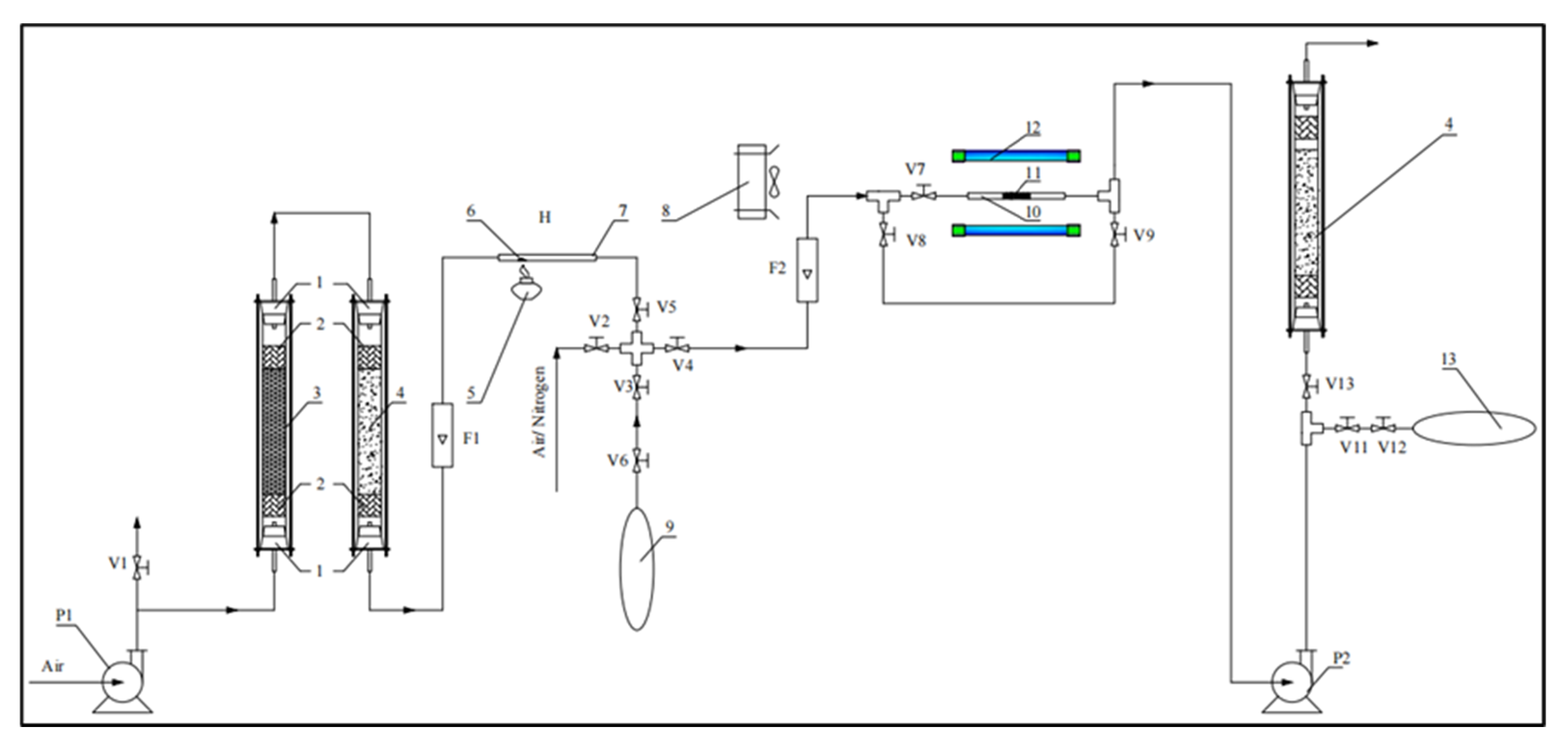
Figure 2 shows the experimental set up of the system in which the photocatalytic degradation experiments were carried out. Toluene concentrations before and after reaction were determined. The air was pumped by the first compressor (P1) and then filtered through two glass tubes. The first glass tube contained silicates (3) in the middle of it to remove the moisture from the air, while the second tube contained activated carbon to clean the air and remove residual moisture. They both had glass wool (2) and were sealed by rubber cap (1) to avoid air loss. F1 flow meter (F1) was used to control the stream. A quartz tube (7) (5 mm in diameter) contained the sample drop (6), which was a mixture of toluene and distilled water. Below the tube, there was an alcohol burner (5) evaporating the sample. The four-way cock was used to change the direction of the stream. The air containing toluene was pumped into a TEDLAR 3 L air bag (9) to stabilize the concentration of inlet gas. Then, the second compressor (P2) was used to withdraw the air from this air bag for photocatalytic degradation. F2 flow meter (F2) controlled the air flow before passing through photocatalyst layer as well as the time for reacted air collecting. A quartz tube (10) (100 mm in length, 5 mm in diameter) was used as a packed-bed reactor filled with previously prepared TixIr1-xO2 photocatalyst. Two identical UV lamps (12) (Ecomax, 25 W) with 132.6 W/m2 irradiation power and minimum wavelength of 255 nm were used as light sources. The fan (8) helped to cool these two lamps. Another TEDLAR air bag (13) was used to collect the reacted air for further analysis. Gas chromatography (Agilent 6890 N Network Gas Chromatograph) was then used to determine the concentration of toluene in the inlet collected by bag (9) (C0) and the outlet collected by bag (13) (C). The efficiency (E) in each experiment was then calculated as follows: E = 1 C C 0 100 % . Finally, the air was pumped through a glass tube containing activated carbon to ensure the harmlessness of the outlet gas.
The experiments were carried out in the following steps:
  • The air bag was connected to V3 valve. Then, V6 valve of the air bag was opened. F1 flow meter was adjusted to the rate of 1 L/min while other valves were closed. The glass wool was padded into the tubes.
  • A sample drop (containing 0.02 mL of toluene and 0.11 mL distilled water) was put in the reaction tube. Then, the alcohol burner was used to evaporate the drop in 1 min.
  • V3 and V5 valves were opened to collect the air in 03 min. When the bag was full, V6 valve was closed, the P1 compressor was turned off and then other valves were closed.
  • A measure of 0.1 g of synthesized photocatalyst was placed evenly in the reaction tube. Then, the cooling fan and UV lamps were turned on 10 min before reacting to stabilize the light source.
  • Another air bag was connected to V11 valve and V12 valve of this airbag was also opened.
  • P2 compressor and F2 flow meter were adjusted to desired flow rates. Then, V3, V4, V7, and V11 valves were opened, while V5, V6, V8, V9, and V13 valves were closed.
  • The air was collected in T (minutes) needed for investigation. When the bag containing outlet gas was full, V11, V12 valves were closed. Then, the bag was removed, then P2 compressor and UV lamps were turned off.
  • After reactions, the tube containing sample drop and reaction tube were cleaned. The system was also cleaned by blowing air through it.
  • The air bags were labeled and sent to the analyzing center for gas chromatography analysis.
The airtightness of the system was ensured by using soap solution at the connecting joints. There were no soap bubbles, therefore the system was airtight. All experiments were performed at room temperature ( 30 °C). The experiment to examine toluene degradation under visible light was also conducted with a similar procedure. The system was exposed to natural light from the sun instead of using UV lamps as light source. The experiment was carried out in the steps mentioned above and gas samples were collected in air bags for further analysis. Each experiment was repeated three times to ensure the precision.

3. Results and Discussion

Material Characteristics

Figure 3 gives information of XRD measurement of the photocatalysts with different doped Ir concentrations. The results show the diffraction peaks relating to tetragonal anatase phase. The peaks of IrO 2 were not detected, which could be explained by the low loading content of iridium as well as the successful doping of this metal into the TiO 2 structure. There were also the peaks (at 2   θ = 27 ° and 2   θ = 36 ° ) that corresponded to the crystallographic orientation of rutile phase (JCPDS 21-1276). The positive difference of Ir4+ radius compared to Ti4+ radius might result in crystallinity reduction, limiting the formation of rutile phase, because of this, the peaks of this phase decreased their intensity when the concentration of iridium increased. Moreover, it might due to the synthesis used being hydrothermal synthesis at 250 °C in 8 h. At this reaction condition, amorphous TiO2 was completely transformed into anatase TiO2 but not enough for the transformation from anatase phase to rutile phase [27,28,29]. The intensive peaks show that the anatase phase formed accounted for a larger proportion than the rutile phase did. This is consistent with the previous studies [27,28,29]. However, the anatase/rutile TiO 2 ratio gradually increased with the increase of doped iridium concentration. This suggests that doped iridium in the TiO 2 matrix might inhibit the formation of a rutile phase [30]. Due to the larger radius of Ir3+ ions compared to that of Ti4+ ions, resulting in distortion of the TiO2 structure, the observed peaks at 2   θ range of 24.5–25° of the materials shifted toward higher values, which showed the reduction in the lattice parameter of TiO2 [31,32]. This could be explained by the effect of Schottky defects in the anionic sublattice, which are the result of the replacement of tetravalent Ti ions with trivalent Ir ions, forming in oxygen vacancies in the lattice for electrostatic balance. The rutile phase in undoped TiO2 was higher as compared to the doped TiO2, which could be explained by the iridium doping process. The positive difference of Ir4+ radius compared to Ti4+ radius might have resulted in a crystallinity reduction, limiting the formation of the rutile phase.
Transmission electron microscopy (TEM) was used to determine the morphology and particle size of the Ir-doped TiO 2 photocatalyst. Figure 4 indicates that the particles mainly had a diameter of 10–15 nm with spherical morphology. In addition, with the increase of iridium concentration, the crystallite size decreased, which could be explained by the distortion of TiO2 structure after the doping process. Moreover, the particles were uniformly distributed although the clusters still exist. Table 1 shows that the elemental composition of Ir was approximately close to theory, thus it suggests that the sample’s composition can be controlled facilely by tuning the ratio of the precursor.
To analyze the distribution of elements in the as-prepared photocatalyst, SEM photographs and EDX were used with 1.0 mol% Ir-doped TiO 2 material. The data in Figure 5 suggest that titanium, iridium, and oxygen were evenly distributed throughout the material structure.
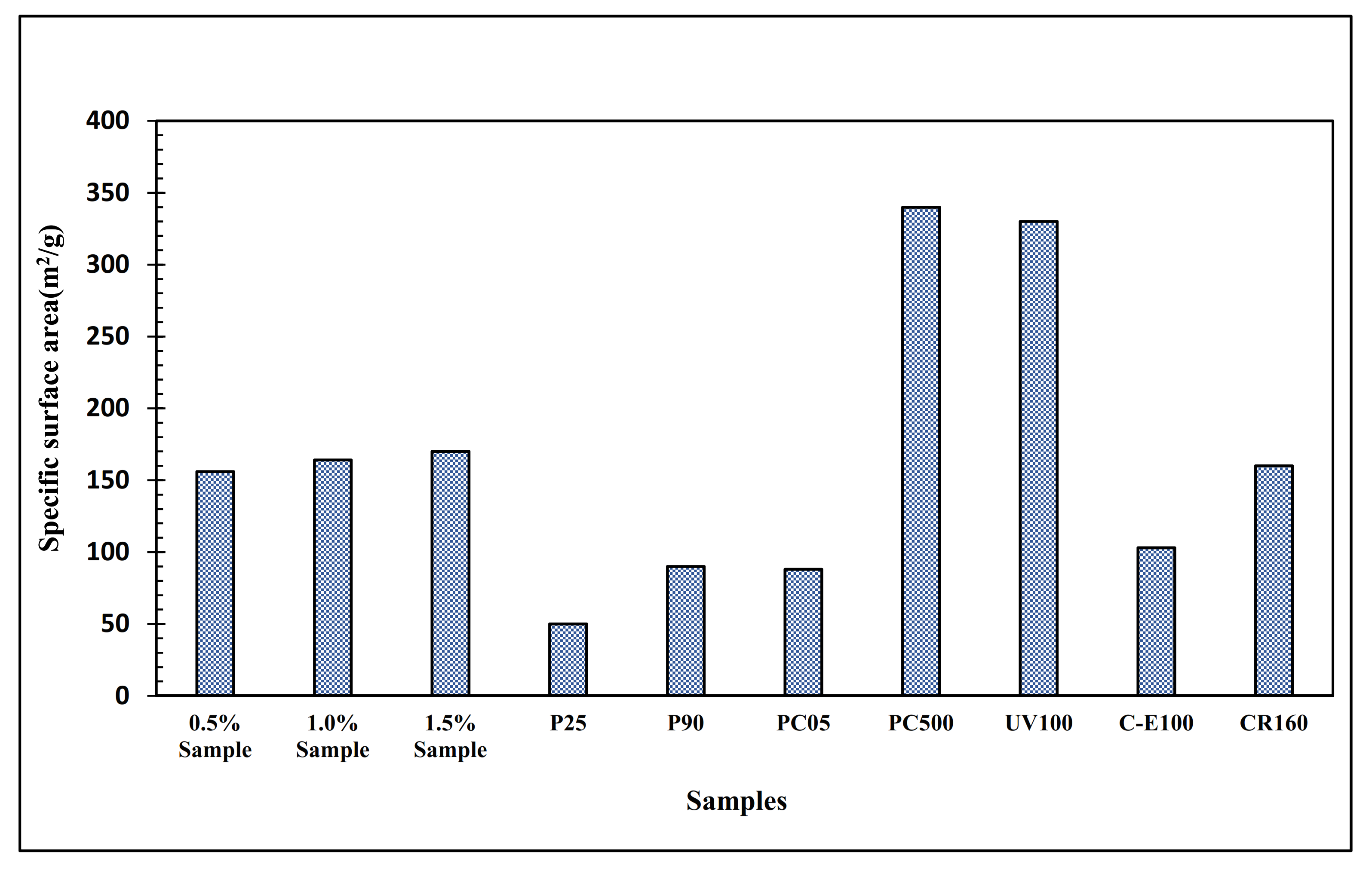
The specific surface areas of Ir-doped TiO 2 with Ir concentrations of 0.5; 1.0 and 1.5 mol% were 156, 164 and 170 (m2/g), respectively. Figure 6 compares the specific surface area of these samples to that of some commercial photocatalysts reported in other literature [33]. The surface areas of these samples were significantly higher than those of some commercially available photocatalysts such as P25, P90, C-E100. Its high value is presumably the result of the lack of coalescence of the primary particles. However, it appears that the manufacturing method of PC-500 and UV-100 is more advantageous since these photocatalysts had significantly higher specific areas. Meanwhile, the CR-160’s specific area was only slightly different from those of the prepared samples. The surface areas of the undoped TiO2 prepared by the same method, Ir-doped TiO2 and other doped TiO2 are shown in Table 2.
Regarding the formation of the pores, the previous study (Energy Environ. Sci. 2011, 4, 4194–4200) indicated that all the atomic positions of Ti in the unit cell were considered for substitution by Ru to obtain the lowest energy. This caused the O vacancies in the structure of TiO2. Therefore, in this work, the pore diameter and pore volume of catalyst based Ir-doped TiO2 could be modified by the doping process as Ru-doped TiO2. However, we are going to study the detailed effect of this observation next time.
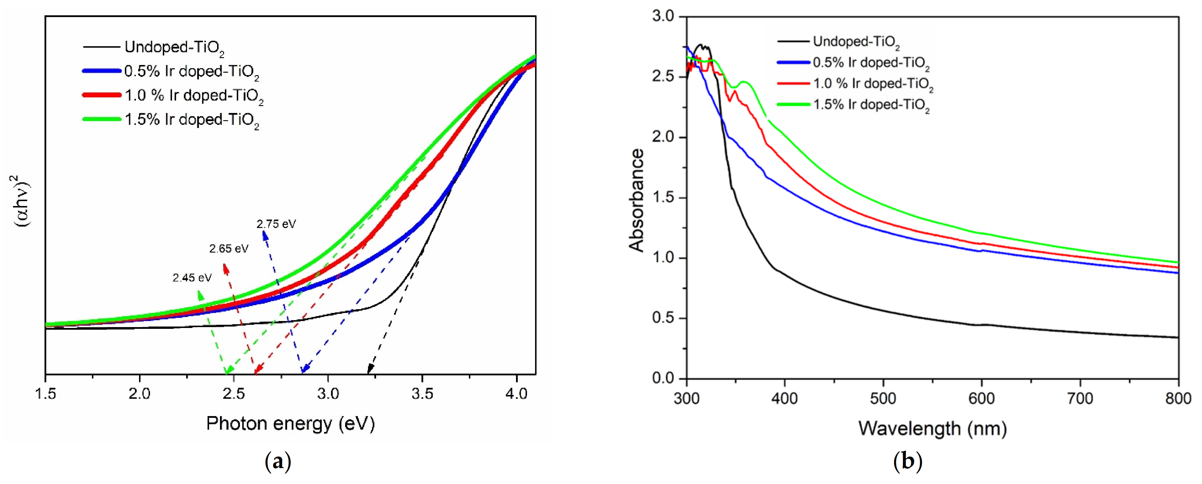
UV–Vis absorption spectroscopy was used to determine the optical properties of the Ir-doped TiO 2 material and pristine TiO 2 photocatalyst. Figure 7 indicates the differences in the UV–Vis absorbance of Ir-doped TiO 2 samples compared with the anatase TiO 2 . In Figure 7a, the absorption edge of TiO 2 was shifted toward a longer wavelength by the iridium doping process which means that the absorption range of TiO 2 was expanded to the visible region. Furthermore, the increase in iridium concentration resulted in the enhancement of the red shift of TiO 2 . This could be explained by the formation of oxygen vacancies which are a result of the doping process. Introducing iridium into TiO 2 lattice might generate a high oxygen vacancy concentration, creating a minor band below the conductance band (CB) of TiO 2 photocatalyst [35,36]. Therefore, in Figure 7b, the average absorbed photon energies of Ir-doped TiO 2 materials were significantly lower than that of pristine TiO 2 . These results suggest that the absorption range of TiO 2 could be expanded toward a longer wavelength to visible light by the doping iridium process. This result is consistent with previous studies [37,38,39,40].
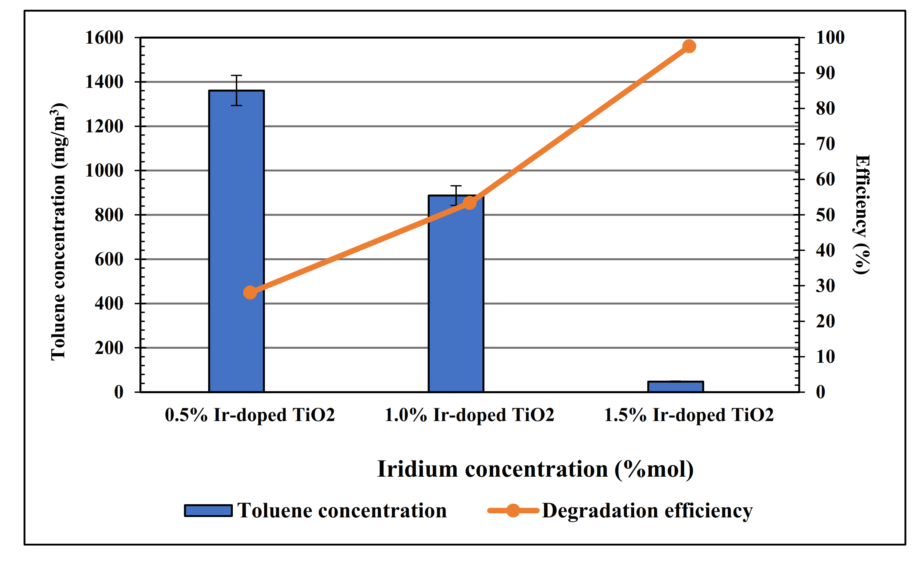
The air containing 1901 mg/m3 toluene was pumped through the system to determine the photocatalytic activity of the photocatalysts having different iridium concentrations (0.5, 1.0 and 1.5 mol%) and the concentrations of residual toluene were 1361, 887 and 47.5 mg/m3 respectively. As shown in Figure 8, between the three photocatalysts, the 1.5 mol% Ir-doped photocatalyst had the highest degrading efficiency while 0.5 mol% Ir-doped sample had the lowest one. We found that the efficiency in toluene degradation without illumination was 3.45%; this could be explained by the adsorption of toluene on the catalyst surface. Importantly, the degradation efficiency of 1.5 mol% Ir-doped material was more than 97%, while the TiO 2 /ACFs photocatalyst only had a conversion rate of 14.2% at 25 °C and relative humidity of 60% [41]. This could be explained by the impact of the iridium doping process on TiO 2 material which helps to reduce the electron-hole recombination rate by trapping charge carriers. A mechanism of dopant trapping, and mediating charges was proposed by Choi et al. [42], indicating that each photocatalyst should have an optimum metal doped concentration. Our finding is consistent with that of Choi et al. whereas the efficiency would rise to a certain value with the increase of doped iridium concentration. In the present study, 1.5 mol% iridium-doped material showed the higher decomposing efficiency compared to two other doped TiO 2 . Therefore, in the following experiments, we used 1.5 mol% Ir-doped TiO 2 to make further investigations. In this work, the 1.5% ratio of iridium was chosen to dope into TiO2 because only a small amount of iridium can reduce the absorbed photon energy of TiO2, therefore we could apply this material in air treatment. However, reducing the bandgap may be not good due to the recombination of hole and electron so that it would decrease the efficiency of catalyst performance. In addition, iridium is quite expensive, so a larger ratio of iridium would not be so economically effective.
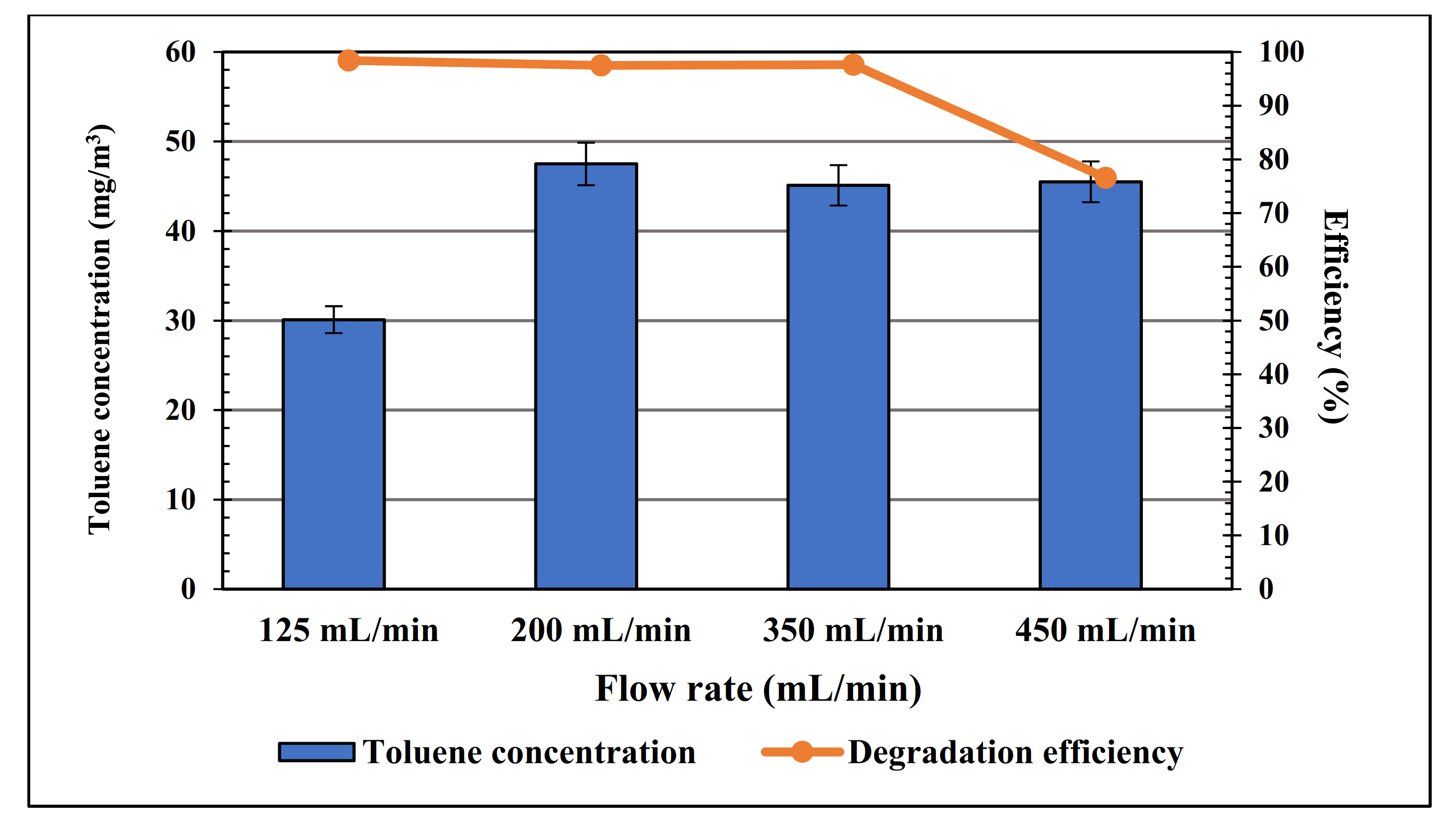
Air at 125, 200 and 350, and 450 mL/min flow rates was blown through the system containing a 1.5 mol% Ir sample to determine the impact of flow rate on decomposing efficiency. The corresponding efficiencies were 98.42, 97.5 and 97.63, 76.55% indicating that with the range of flow rates between 125–350 (mL/min) used in this experiment there was no significant impact on toluene treating efficiency, suggesting that in this flow rate range, the toluene degradation efficiency was good and reaction time was enough to degrade the toluene (Figure 9). However, when increasing the flow rate to 450 mL/min, the toluene degradation efficiency was reduced to 76.55%. It might suggest that the flow rate of 350 mL/min should be chosen for the optimum flow rate and 98.42% was the highest degradation capacity that Ir-doped TiO 2 could reach in the study.
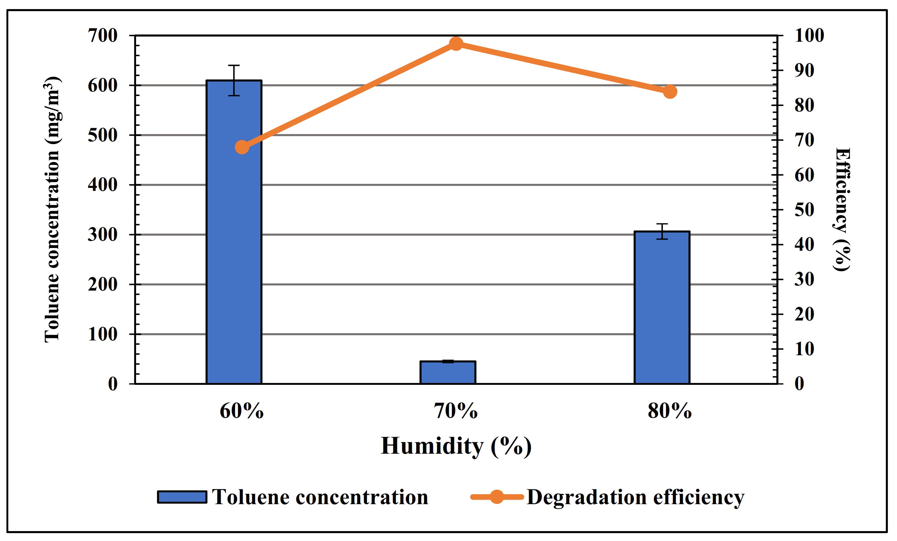
Regarding the impact of humidity on the photocatalytic activity, the air containing 1901 mg/m3 toluene was also used to evaluate the photocatalytic decomposition of toluene under different humidity conditions. After treatment by the toluene degradation system in Figure 2, the concentrations of residual toluene, corresponding to 60, 70 and 80% humidity conditions, were 609.6, 45.1 and 306.3 mg/m3 while the decomposing efficiencies (Figure 10) were 67.93, 97.63 and 83.89%, respectively. It could be explained by the presence of hydroxyl radicals, formed from water by the photodegradation reaction, which play an important role as the main oxidants along with adsorbed O 2 in decomposing VOCs [30,31,43,44]. Choi et al. also suggested that hydroxyl radicals could recombine with metal ions which acted as trapping sites and eliminate charges. Therefore, the rise in humidity of the air increased the toluene decomposing efficiency of Ir-doped TiO 2 photocatalyst.
From our findings, it is indicated that toluene is a molecule hard to be degraded photocatalytically, but high conversion was obtained using high initial concentration of toluene (1900 mg/m3). This is a remarkable result in our work, so we have measured the CO 2 for further confirmation of the CO 2 yields at different Ir-doping ratios with a high initial concentration of toluene (1900 mg/m3) in Table 3.
From the results we can see that the CO 2 yields obtained were quite high (64.35% for 1.5% Ir-doped TiO 2 ), this result corresponds with previous work [45].
The toluene degradation reaction at optimum conditions was repeated three times and the corresponding efficiencies were 97.60, 97.61, and 97.63%. This result suggests that VOC removal could be the saturation of the catalyst surface by reaction byproduct. We found that the toluene degradation efficiency under visible light was 46.25% in 8.5 min compared to the efficiency under UV light of approximately 97% in 8.5 min. The efficient degradation of toluene under visible light could be improved when the reaction is extended longer. In comparison with some previous studies, the Ir-doped TiO 2 photocatalyst showed a significantly high degradation efficiency (Table 4).

4. Conclusions

In conclusion, we have successfully prepared the novel nanostructured Ir-doped TiO 2 photocatalyst with different iridium mol fractions by a hydrothermal method without employing any surfactant or subsequent heat treatment. The results showed that the obtained photocatalyst had the particle diameter of 10–15 nm and exhibited the co-existence of rutile phase and anatase phase, and the ratio of rutile phase decreased with the increase of dopant concentration. The surface area of the as-prepared material was more than 150 m2/g. In addition, iridium was uniformly dispersed on TiO 2 and interacted with substituted Ti4+ and O2− ions, resulting in oxygen vacancies in the lattice for electrostatic balance. Regarding its optical properties, the adsorption range of the Ir-doped TiO 2 photocatalyst was expanded to visible light due to the existence of rutile TiO 2 . This study found that the iridium mole fraction and the humidity of the air had sufficient impact on the toluene decomposition of this photocatalyst. On the other hand, the air flow rates from 125 to 350 mL/min exhibited no effect on toluene degrading efficiency.

Author Contributions

Writing—original draft preparation, V.T.T.H. and D.H.C.; software, T.K.N.T. and K.Q.B.; data curation, K.Q.B. and N.T.T.N.; conceptualization, N.T.T.N. and T.K.N.T.; methodology, D.H.C. and S.N.T.; formal analysis L.G.B. and S.N.T.; writing—review and editing L.G.B. and V.T.T.H. All authors have read and agreed to the published version of the manuscript.

Funding

This work is supported by Project of Ho Chi Minh City of Department of Science and Technology (DOST)-2019/HĐ-QPTKHCN. Thanks to Pham Minh Toan, Nguyen Minh Nhat, Huynh Thien Tai, Pham Quoc Hau, Vu Thi Hanh Thu for your support for this work.

Institutional Review Board Statement

Not applicable.

Informed Consent Statement

Not applicable.

Data Availability Statement

All the data is available within the manuscript.

Conflicts of Interest

The authors declare no conflict of interest.

References

  1. Yang, K.; Wang, C.; Xue, S.; Li, W.; Liu, J.; Li, L. The identification, health risks and olfactory effects assessment of VOCs released from the wastewater storage tank in a pesticide plant. Ecotoxicol. Environ. Saf. 2019, 184, 109665. [Google Scholar] [CrossRef] [PubMed]
  2. Antonelli, M.; Donelli, D.; Barbieri, G.; Valussi, M.; Maggini, V.; Firenzuoli, F. Forest Volatile Organic Compounds and Their Effects on Human Health: A State-of-the-Art Review. Int. J. Environ. Res. Public Health 2020, 17, 6506. [Google Scholar] [CrossRef]
  3. Kelly, F.J.; Fussell, J.C. Improving indoor air quality, health and performance within environments where people live, travel, learn and work. Atmos. Environ. 2018, 200, 90–109. [Google Scholar] [CrossRef] [Green Version]
  4. Tomatis, M.; Moreira, M.T.; Xu, H.; Deng, W.; He, J.; Parvez, A.M. Removal of VOCs from waste gases using various thermal oxidizers: A comparative study based on life cycle assessment and cost analysis in China. J. Clean. Prod. 2019, 233, 808–818. [Google Scholar] [CrossRef]
  5. Li, X.; Zhang, L.; Yang, Z.; He, Z.; Wang, P.; Yan, Y.; Ran, J. Hydrophobic modified activated carbon using PDMS for the adsorption of VOCs in humid condition. Sep. Purif. Technol. 2020, 239, 116517. [Google Scholar] [CrossRef]
  6. Yadav, A.A.; Kang, S.-W.; Hunge, Y.M. Photocatalytic degradation of Rhodamine B using graphitic carbon nitride photocatalyst. J. Mater. Sci. Mater. Electron. 2021, 32, 15577–15585. [Google Scholar] [CrossRef]
  7. Hunge, Y.M.; Yadav, A.A.; Kang, S.-W.; Kim, H. Photocatalytic degradation of tetracycline antibiotics using hydrothermally synthesized two-dimensional molybdenum disulfide/titanium dioxide composites. J. Colloid Interface Sci. 2022, 606, 454–463. [Google Scholar] [CrossRef]
  8. Dong, H.; Zeng, G.; Tang, L.; Fan, C.; Zhang, C.; He, X.; He, Y. An overview on limitations of TiO2-based particles for photocatalytic degradation of organic pollutants and the corresponding countermeasures. Water Res. 2015, 79, 128–146. [Google Scholar] [CrossRef]
  9. Jin, M.; Zhang, X.; Pu, H.; Nishimoto, S.; Murakami, T.; Fujishima, A. Photochromism-based detection of volatile organic compounds by W-doped TiO2 nanofibers. J. Colloid Interface Sci. 2011, 362, 188–193. [Google Scholar] [CrossRef]
  10. Hinojosa-Reyes, M.; Arriaga, S.; Diaz-Torres, L.A.; Rodríguez-González, V. Gas-phase photocatalytic decomposition of ethylbenzene over perlite granules coated with indium doped TiO2. Chem. Eng. J. 2013, 224, 106–113. [Google Scholar] [CrossRef]
  11. Inturi, S.N.R.; Boningari, T.; Suidan, M.; Smirniotis, P.G. Visible-light-induced photodegradation of gas phase acetonitrile using aerosol-made transition metal (V, Cr, Fe, Co, Mn, Mo, Ni, Cu, Y, Ce, and Zr) doped TiO2. Appl. Catal. B Environ. 2014, 144, 333–342. [Google Scholar] [CrossRef]
  12. Huang, H.; Huang, H.; Zhang, L.; Hu, P.; Ye, X.; Leung, D.Y.C. Enhanced degradation of gaseous benzene under vacuum ultraviolet (VUV) irradiation over TiO2 modified by transition metals. Chem. Eng. J. 2015, 259, 534–541. [Google Scholar] [CrossRef]
  13. Oseghe, E.O.; Ndungu, P.G.; Jonnalagadda, S.B. Photocatalytic degradation of 4-chloro-2-methylphenoxyacetic acid using W-doped TiO2. J. Photochem. Photobiol. A Chem. 2015, 312, 96–106. [Google Scholar] [CrossRef]
  14. Binas, V.; Stefanopoulos, V.; Kiriakidis, G.; Papagiannakopoulos, P. Photocatalytic oxidation of gaseous benzene, toluene and xylene under UV and visible irradiation over Mn-doped TiO2 nanoparticles. J. Mater. 2018, 5, 56–65. [Google Scholar] [CrossRef]
  15. Li, X.; Guo, Z.; He, T. The doping mechanism of Cr into TiO2 and its influence on the photocatalytic performance. Phys. Chem. Chem. Phys. 2013, 15, 20037–20045. [Google Scholar] [CrossRef] [PubMed]
  16. Vu, A.T.; Nguyen, Q.T.; Bui, T.H.L.; Tran, M.C.; Dang, T.P.; Tran, T.K.H. Synthesis and characterization of TiO2 photocatalyst doped by transition metal ions (Fe3+, Cr3+ and V5+). Adv. Nat. Sci. Nanosci. Nanotechnol. 2010, 1, 15009. [Google Scholar] [CrossRef] [Green Version]
  17. Bartkowiak, A.; Korolevych, O.; Chiarello, G.; Makowska-Janusik, M.; Zalas, M. How Can the Introduction of Zr4+ Ions into TiO2 Nanomaterial Impact the DSSC Photoconversion Efficiency? A Comprehensive Theoretical and Experimental Consideration. Materials 2021, 14, 2955. [Google Scholar] [CrossRef] [PubMed]
  18. Kasach, A.A.; Kharytonau, D.S.; Paspelau, A.V.; Ryl, J.; Sergievich, D.S.; Zharskii, I.M.; Kurilo, I.I. Effect of TiO2 Concentration on Microstructure and Properties of Composite Cu–Sn–TiO2 Coatings Obtained by Electrodeposition. Materials 2021, 14, 6179. [Google Scholar] [CrossRef]
  19. Fernandes, S.; da Silva, J.C.G.E.; da Silva, L.P. Life cycle assessment of the sustainability of enhancing the photodegradation activity of TiO2 with metal-doping. Materials 2020, 13, 1487. [Google Scholar] [CrossRef] [Green Version]
  20. Elmehasseb, I.; Kandil, S.; Elgendy, K. Advanced visible-light applications utilizing modified Zn-doped TiO2 nanoparticles via non-metal in situ dual doping for wastewater detoxification. Optik 2020, 213, 164654. [Google Scholar] [CrossRef]
  21. Zou, F.; Hu, J.; Miao, W.; Shen, Y.; Ding, J.; Jing, X. Synthesis and Characterization of Enhanced Photocatalytic Activity with Li+-Doping Nanosized TiO2 Catalyst. ACS Omega 2020, 5, 28510–28516. [Google Scholar] [CrossRef] [PubMed]
  22. Babajani, N.; Jamshidi, S. Investigation of photocatalytic malachite green degradation by iridium doped zinc oxide nanoparticles: Application of response surface methodology. J. Alloy. Compd. 2018, 782, 533–544. [Google Scholar] [CrossRef]
  23. Dhanalakshmi, M.; Saravanakumar, K.; Prabavathi, S.L.; Abinaya, M.; Muthuraj, V. Fabrication of novel surface plasmon resonance induced visible light driven iridium decorated SnO2 nanorods for degradation of organic contaminants. J. Alloys Compd. 2018, 763, 512–524. [Google Scholar] [CrossRef]
  24. Rojas, J.V.; Castano, C.H. Radiolytic synthesis of iridium nanoparticles onto carbon nanotubes. J. Nanoparticle Res. 2014, 16, 1–5. [Google Scholar] [CrossRef]
  25. Pawluk, T.; Hirata, Y.; Wang, L. Studies of Iridium Nanoparticles Using Density Functional Theory Calculations. J. Phys. Chem. B 2005, 109, 20817–20823. [Google Scholar] [CrossRef]
  26. Atanasoska, L.; Gupta, P.; Deng, C.; Warner, R.; Larson, S.; Thompson, J. XPS, AES, and Electrochemical Study of Iridium Oxide Coating Materials for Cardiovascular Stent Application. ECS Trans. 2009, 16, 37–48. [Google Scholar] [CrossRef]
  27. Huynh, T.T.; Van Nguyen, A.; Pham, H.Q.; Bach, L.G.; Ho, V.T.T. Synthesis the New Nanostructure Ti0.7Ir0.3O2 via Low Temperature Hydrothermal Process. Appl. Mech. Mater. 2018, 876, 64–70. [Google Scholar] [CrossRef]
  28. Huynh, T.T.; Van Nguyen, A.; Pham, H.Q.; Vinh, N.H.; Bach, L.G.; Ho, V.T.T. One-Step Hydrothermal Synthesis of a New Nanostructure Ti0.7Ir0.3O2 for Enhanced Electrical Conductivity: The Effect of pH on the Formation of Nanostructure. J. Nanosci. Nanotechnol. 2018, 18, 6928–6933. [Google Scholar] [CrossRef]
  29. Van Nguyen, A.; Huynh, T.T.; Pham, H.Q.; Phan, V.T.T.; Nguyen, V.A.; Ho, V.T.T. Novel nanorod Ti0.7Ir0.3O2 prepared by facile hydrothermal process: A promising non-carbon support for Pt in PEMFCs. Int. J. Hydrog. Energy 2018, 44, 2361–2371. [Google Scholar] [CrossRef]
  30. Wang, S.; Liu, B.; Zhu, Y.; Ma, Z.; Liu, B.; Miao, X.; Ma, R.; Wang, C. Enhanced performance of TiO2-based perovskite solar cells with Ru-doped TiO2 electron transport layer. Sol. Energy 2018, 169, 335–342. [Google Scholar] [CrossRef]
  31. Savini, A.; Bucci, A.; Nocchetti, M.; Vivani, R.; Idriss, H.; Macchioni, A. Activity and Recyclability of an Iridium–EDTA Water Oxidation Catalyst Immobilized onto Rutile TiO2. ACS Catal. 2015, 5, 264–271. [Google Scholar] [CrossRef]
  32. Kumaresan, L.; Mahalakshmi, M.; Palanichamy, M.; Murugesan, V. Synthesis, characterization, and photocatalytic activity of Sr2+ doped TiO2 nanoplates. Ind. Eng. Chem. Res. 2010, 49, 1480–1485. [Google Scholar] [CrossRef]
  33. Holm, A.; Hamandi, M.; Simonet, F.; Jouguet, B.; Dappozze, F.; Guillard, C. Impact of rutile and anatase phase on the photocatalytic decomposition of lactic acid. Appl. Catal. B Environ. 2019, 253, 96–104. [Google Scholar] [CrossRef]
  34. Li, Z.; Shen, W.; He, W.; Zu, X. Effect of Fe-doped TiO2 nanoparticle derived from modified hydrothermal process on the photocatalytic degradation performance on methylene blue. J. Hazard. Mater. 2008, 155, 590–594. [Google Scholar] [CrossRef] [PubMed]
  35. Caudillo-Flores, U.; Muñoz-Batista, M.J.; Cortés, J.A.; Fernández-García, M.; Kubacka, A. UV and visible light driven H2 photo-production using Nb-doped TiO2: Comparing Pt and Pd co-catalysts. Mol. Catal. 2017, 437, 1–10. [Google Scholar] [CrossRef]
  36. Munir, S.; Shah, S.M.; Hussain, H.; Khan, R.A. Effect of carrier concentration on the optical band gap of TiO2 nanoparticles. Mater. Des. 2016, 92, 64–72. [Google Scholar] [CrossRef]
  37. El Mragui, A.; Logvina, Y.; Da Silva, L.P.; Zegaoui, O.; Da Silva, J.C.E. Synthesis of Fe- and Co-Doped TiO2 with Improved Photocatalytic Activity Under Visible Irradiation Toward Carbamazepine Degradation. Materials 2019, 12, 3874. [Google Scholar] [CrossRef] [Green Version]
  38. Yang, S.; Ohtani, B. Substitutionally rhodium(IV)-doped titania showing photocatalytic activity toward organics oxidation under visible-light irradiation. Catal. Today 2021, 380, 25–31. [Google Scholar] [CrossRef]
  39. Feng, H.; Zhang, M.-H.; Yu, L.E. Hydrothermal synthesis and photocatalytic performance of metal-ions doped TiO2. Appl. Catal. A Gen. 2012, 413–414, 238–244. [Google Scholar] [CrossRef]
  40. Liu, S.; Guo, E.; Yin, L. Tailored visible-light driven anatase TiO2 photocatalysts based on controllable metal ion doping and ordered mesoporous structure. J. Mater. Chem. 2012, 22, 5031–5041. [Google Scholar] [CrossRef]
  41. Zhou, H.; Zhang, Y. Electrochemically Self-Doped TiO2 Nanotube Arrays for Supercapacitors. J. Phys. Chem. C 2014, 118, 5626–5636. [Google Scholar] [CrossRef]
  42. Tian, J.; Zhao, P.; Zhang, S.; Huo, G.; Suo, Z.; Yue, Z.; Zhang, S.; Huang, W.; Zhu, B. Platinum and Iridium Oxide Co-modified TiO2 Nanotubes Array Based Photoelectrochemical Sensors for Glutathione. Nanomaterials 2020, 10, 522. [Google Scholar] [CrossRef] [Green Version]
  43. Shayegan, Z.; Lee, C.-S.; Haghighat, F. TiO2 photocatalyst for removal of volatile organic compounds in gas phase—A review. Chem. Eng. J. 2018, 334, 2408–2439. [Google Scholar] [CrossRef] [Green Version]
  44. Choi, W.; Termin, A.; Hoffmann, M.R. The Role of Metal Ion Dopants in Quantum-Sized TiO2: Correlation between Photoreactivity and Charge Carrier Recombination Dynamics. J. Phys. Chem. 1994, 98, 13669–13679. [Google Scholar] [CrossRef]
  45. Mo, J.; Zhang, Y.; Xu, Q.; Lamson, J.J.; Zhao, R. Photocatalytic purification of volatile organic compounds in indoor air: A literature review. Atmos. Environ. 2009, 43, 2229–2246. [Google Scholar] [CrossRef]
  46. Yang, X.; Cao, C.; Erickson, L.; Hohn, K.; Maghirang, R.; Klabunde, K. Synthesis of visible-light-active TiO2-based photocatalysts by carbon and nitrogen doping. J. Catal. 2008, 260, 128–133. [Google Scholar] [CrossRef]
  47. Rodríguez, M.J.H.; Melián, E.P.; Díaz, O.G.; Araña, J.; Macías, M.; Orive, A.G.; Rodríguez, J.M.D. Comparison of supported TiO2 catalysts in the photocatalytic degradation of NOx. J. Mol. Catal. A Chem. 2016, 413, 56–66. [Google Scholar] [CrossRef]
  48. Sharotri, N.; Sharma, D.; Sud, D. Experimental and theoretical investigations of Mn-N-co-doped TiO2 photocatalyst for visible light induced degradation of organic pollutants. J. Mater. Res. Technol. 2019, 8, 3995–4009. [Google Scholar] [CrossRef]
  49. Qiu, X.; Miyauchi, M.; Sunada, K.; Minoshima, M.; Liu, M.; Lu, Y.; Li, D.; Shimodaira, Y.; Hosogi, Y.; Kuroda, Y.; et al. Hybrid CuxO/TiO2 Nanocomposites as Risk-Reduction Materials in Indoor Environments. ACS Nano 2012, 6, 1609–1618. [Google Scholar] [CrossRef]
  50. Zhong, L.; Brancho, J.J.; Batterman, S.; Bartlett, B.M.; Godwin, C. Experimental and modeling study of visible light responsive photocatalytic oxidation (PCO) materials for toluene degradation. Appl. Catal. B Environ. 2017, 216, 122–132. [Google Scholar] [CrossRef] [PubMed]
  51. Abbas, N.; Hussain, M.; Russo, N.; Saracco, G. Studies on the activity and deactivation of novel optimized TiO2 nanoparticles for the abatement of VOCs. Chem. Eng. J. 2011, 175, 330–340. [Google Scholar] [CrossRef]
  52. Khan, R.; Kim, T.-J. Preparation and application of visible-light-responsive Ni-doped and SnO2-coupled TiO2 nanocomposite photocatalysts. J. Hazard. Mater. 2009, 163, 1179–1184. [Google Scholar] [CrossRef] [PubMed]
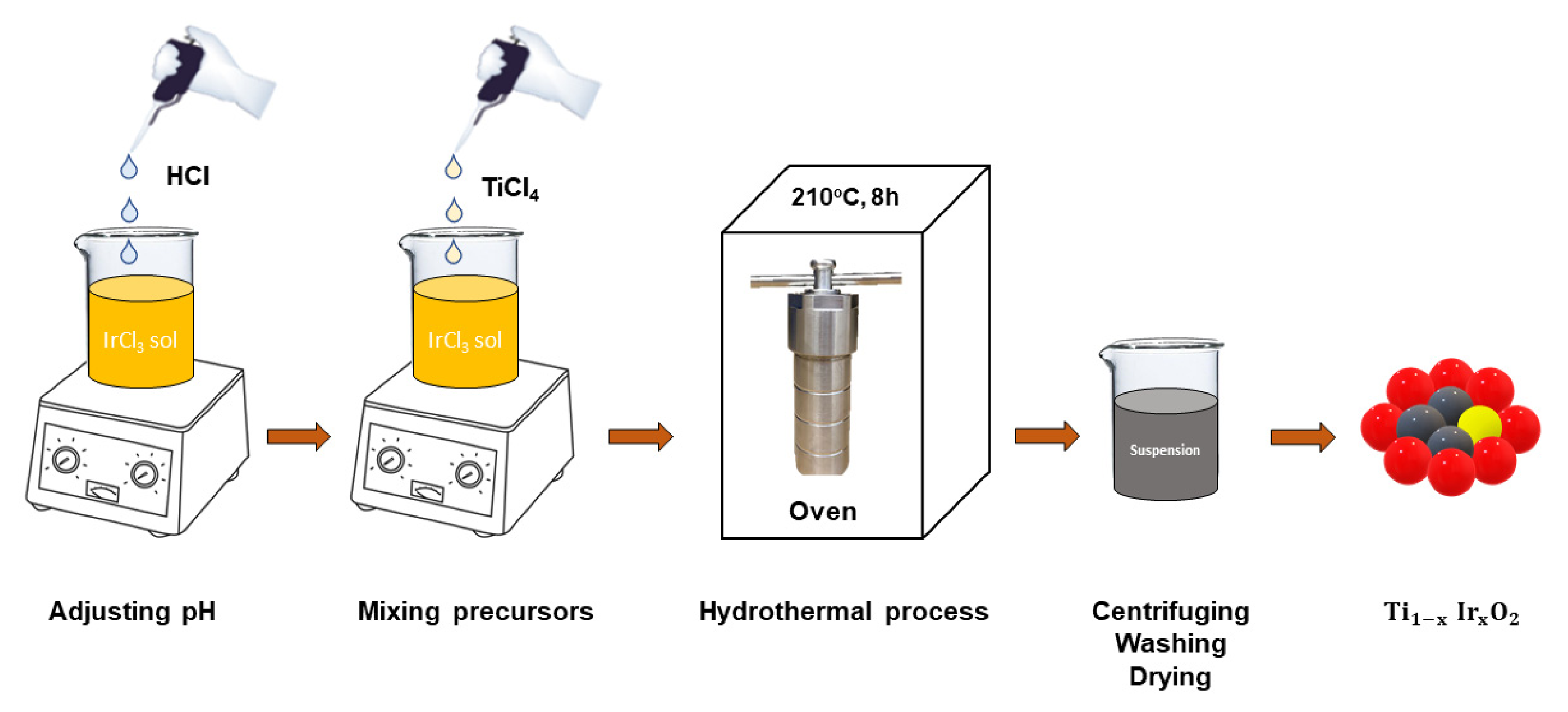
Figure 1. Procedure to synthesize Ir-doped TiO 2 photocatalysts.
Inorganics 10 00029 g001
Figure 2. Schematic of toluene degradation system. 1. Rubber cap; 2. Glass wool; 3. Silica gel; 4. Activated carbon; 5. Alcohol burner; 6. Drops of toluene and water; 7. Quartz tube; 8. Cooling fan; 9. Bag containing inlet gas; 10. Reaction tube; 11. Photocatalyst; 12. UV light; 13. Bag containing outlet gas. P1: Compressor 1; P2: Compressor 2; F1: Flow meter for inlet gas; F2: Flow meter for gas passing through photocatalyst layer.
Inorganics 10 00029 g002
Figure 3. X-ray diffraction patterns of Ir-doped TiO 2 photocatalysts with different Ir-doped ratios of 0.5 mol%, 1.0 mol%, and 1.5 mol% respectively.
Inorganics 10 00029 g003
Figure 4. TEM images of Ir-doped TiO 2 photocatalysts with different iridium concentrations. (a) 0.5 mol% Ir-doped sample; (b) 1.0 mol% Ir-doped sample; (c) 1.5 mol% Ir-doped sample.
Inorganics 10 00029 g004
Figure 5. SEM-EDX elemental mapping of (a) Ti, (b) O, (c) Ir for as-synthesized 1.0 mol% Ir-doped TiO 2 photocatalyst.
Inorganics 10 00029 g005
Figure 6. The specific surface area of Ir-doped TiO 2 photocatalysts with different iridium concentrations and some commercially available photocatalysts.
Inorganics 10 00029 g006
Figure 7. (a) UV–Vis absorbance spectrum and (b) Tauc plot of Ir-doped TiO 2 and pristine TiO 2 .
Inorganics 10 00029 g007
Figure 8. Effect of iridium’s mol fraction on photodegradation efficiency of toluene at 125 mL/min, φ = 70%.
Inorganics 10 00029 g008
Figure 9. Effect of flow rate on photodegradation efficiency of toluene at 1.5 mol% Ir, φ = 70%.
Inorganics 10 00029 g009
Figure 10. Effect of humidity on photodegradation efficiency of toluene at 1.5 mol% Ir, 350 mL/min.
Inorganics 10 00029 g010
Table 1. Percentage of iridium in different samples obtained from EDX analysis.
No.SampleMol% of Iridium
10.5 mol% Ir-doped0.62%
21.0 mol% Ir-doped1.15%
31.5 mol% Ir-doped1.80%
Table 2. Surface area and crystallite size of photocatalysts.
PhotocatalystsUn-Doped TiO2P25P90PC105PC500Ir-Doped TiO2Fe-Doped TiO2
Properties
Surface area (m2/g)50509088340156–170103
Crystallite size (nm)20–3021–301415–255–1010–1513
References[33][33][33][33][33]This work[34]
Table 3. CO 2 resulted from the toluene degradation by different ratios of Ir doped into TiO 2 .
No.SampleToluene Degradation Efficiency (%) C O 2   Yield   ( % )
10.5 mol% Ir-doped TiO 2 28.041.87%
21.0 mol% Ir-doped TiO 2 53.3434.67%
31.5 mol% Ir-doped TiO 2 97.5064.35%
Table 4. The comparison of Ir-doped TiO 2 photocatalyst with previously studied TiO 2 -based materials.
No.MaterialsSynthesis MethodParametersReaction ConditionDegradation EfficiencyReferences
1Co-alloyed TiNbON photocatalyst.Urea-glass synthesis method.-Particle diameter: 1–2 μm.
-Crystalline structure: irregularly shaped surfaces
-Surface area: 40.76 m2/g.
-Band gap: 2.3 eV.
-Toluene concentration: 1–5 ppm.
-RH: 25–65%.
-Irradiation: 42–95 (W/m2) (400–540 nm)
58%[46]
2 TiO 2 nanoparticles (TNPs) photocatalyst.Sol-gel method.-Particle diameter: 10–20 μm.
-Crystalline structure: tetragonal.
-Surface area: 151 m2/g.
-Band gap: 3.17 eV.
-Toluene concentration: 200 ppm.
-Irradiation: UVA (320–400 nm) and UVB (290–320 nm).
40%[47]
3x Ni TiO 2 SnO 2
(x = 0.1, 0.3, 0.5 wt%) photocatalyst.
Sol-gel method and wet-impregnation method.-Crystallite size: 15–16 nm.
-Crystalline structrure: TiO 2 crystalline structure.
-Toluene concentration: 177 ppm.
-Irradiation: visible light source with minimum wavelength of 400 nm.
51%[48]
4 TiO 2 / ACF photocatalyst.Commercial photocatalyst.-Fine TiO 2 particles were coated on the activated carbon fibers.-Surface area: 999.6 m2/g.-T = 25 ± 0.5 °C.
-RH = 15, 30, 45, and 60%.
-Irradiation: UV radiation with a primary wavelength at 254 nm
14.2%[41]
5V-doped TiO2/PU
(6 wt% V-TiO2)
Immobilization of amino titanosiloxane on activated PU combined with using NH4VO3 as precursor.-Surface area: 192.5 m2/g
-Bandgap: 2.83 eV for 6 wt% V-TiO2
-T = 25 °C
-RH = 50%
-AFR = 200 mL/min
-Irradiation: visible light source with minimum wavelength of 400 nm
80%[49]
6MnOx-ZrO2
(MnOx-5% ZrO2)
Co-precipitation with NaOH of Mn3O4 and ZrO2-Crystallite size: 14.5 nm
-Surface area: 85.4 m2/g.
-Bandgap: 3.26 (eV)
-T = 25 °C
-Irradiation: solar lamp (300 W; 10.7 mW/cm2)
84%[50]
7TiO2-MnO2One-step anodic oxidation of Ti–Mn alloys in an ethylene glycol-based electrolyte-Crystallite size: d = 76 ± 9 nm; l = 1.0 ± 1 μm
-Crystalline structure: anatase
-Surface area: 170 m2/g.
-T = 25 °C
-Irradiation: 25 LEDS (wavelength at 465 nm)
43%[51]
8Brookite TiO2-5% CeO2Thermohydrolysis of titanium tetrachloride-Crystalline structure: brookite
-Surface area: 66 m2/g.
-Bandgap: 3.19 (eV)
-T = 25 °C
-Irradiation: solar lamp (300 W; 10.7 mW/cm2)
25%[52]
9Ir-doped TiO 2 photocatalyst.Hydrothermal method.-Particle diameter: 10–15 nm.
-Crystalline structure: tetragonal.
-Surface area: 170 m2/g.
-Toluene concentration: 1900 ppm.
-RH: 60–80%.
-Minimum wavelength: 255 nm
97%Present work
Publisher’s Note: MDPI stays neutral with regard to jurisdictional claims in published maps and institutional affiliations.