Review

The Role of Inorganic Fillers in Electrostatic Discharge Composites

Department of Materials Science, INSTM, University of Milano-Bicocca, Via R. Cozzi 55, 20125 Milan, Italy
*
Author to whom correspondence should be addressed.
Inorganics 2022, 10(12), 222; https://doi.org/10.3390/inorganics10120222
Submission received: 14 October 2022 / Revised: 13 November 2022 / Accepted: 23 November 2022 / Published: 25 November 2022
(This article belongs to the Special Issue Inorganics: 10th Anniversary)

Abstract

:
The occurrence of uncontrolled electrostatic discharge (ESD) is among the major causes of damage in unprotected electronic components during industrial processes. To counteract this undesired phenomenon, ESD composites showing static-dissipative and antistatic responses are developed. In particular, static-dissipative materials are able to slow down the flow of electric charges, whereas antistatic materials directly suppress the initial charges induced by undesired charging by properly dispersing conductive fillers within an insulant matrix and thus forming a conductive filler network. In this context, the purpose of this review is to provide a useful resume of the main fundamentals of the technology necessary for facing electrostatic charging. The formation mechanisms of electrostatic charges at the material surface were described, providing a classification of ESD composites and useful characterization methods. Furthermore, we reported a deep analysis of the role of conductive fillers in the formation of filler networks to allow electric charge movements, along with an overview of the different classes of inorganic conductive fillers exploitable in ESD composites, evidencing pros/cons and criticalities of each category of inorganic fillers.

1. Introduction

Electrostatic discharge (ESD) is a physical phenomenon occurring at the surface of insulating (or ungrounded) materials, and it consists of the rapid flow of electrons (i.e., static electricity) between two charged surfaces [1,2,3,4]. The accumulation of static electricity is due to the excess (or lack) of electrons on the surface of a material which consequently generates electrified surfaces (i.e., ESD potential). Once these charged surfaces are put in contact with a grounded object (which acts as ground), the charge balance is restored through the rapid release of an electrostatic discharge from the charged surface toward the grounded objects [5]. In particular circumstances, this phenomenon can generate relevant risks in most industrial processes, as it can damage unprotected electronic components [6] and cause serious hazards to human health [7]. For these reasons, avoiding the undesired accumulation of static electricity is desirable.
In electronics manufacturing, the sensitivity of electronic and microelectronic devices to ESD phenomena became a relevant concern after the technological rise related to integrated circuits (ICs) [8]. According to the literature, ca. 35% of integrated circuit failures in the semiconductor industry are due to uncontrolled ESD phenomena, with an overall cost estimated being ca. $ 5 billion per year according to the Electrical Over-Stress/Electro-Static Discharge (EOS/ESD) Association [8,9], reaching up to 70% of the overall failures depending on the industry field [5]. As reported by Voldman [4], ESD and other electricity-related breakdowns in gas, liquid, and solid substances are an important area of interest in the design of new processes and products since ESD failures are not solely related to (micro)electronics but affect every industrial process where the control of static electricity becomes a relevant task [5,10,11,12,13,14]. A typical example of an electricity-related breakdown is the electrical overstress (EOS) generated when an electrical device reaches a maximum limit in terms of voltage/current across or power dissipated with serious consequent damage.
In this context, the introduction of ESD protection systems is becoming mandatory, in particular for electronic packaging. Thus, several blends and composites containing specific inorganic and organic fillers/additives able to introduce an electric response in insulating substrates (mostly polymeric materials) have been deeply investigated (e.g., refer to [15,16,17,18,19,20]) and still deserve attention by worldwide researchers and industries.
Since this topic is very transversal (as it interests physics, chemistry, and engineering), this review aims at summarizing the main features of ESD-related concerns with a particular emphasis on the strict correlation between ESD and polymer-based materials/composites both in terms of the materials’ properties and processes. This manuscript produces a practical guide on the main fundamentals of ESD materials, presented in a hopefully clear manner to possible users interested in this very specific niche but also very important technological field.

2. Electrostatic Charging Mechanisms and Definitions: A Phenomenological Survey

The formation of electric charges at the surface of objects can be favored by four different mechanisms, namely: (i) triboelectric (contact-induced) charging [21], (ii) piezoelectric (pressure-induced) charging [22], (iii) pyroelectric (heat-induced) charging [23], and (iv) electrostatic (charge-induced) charging or induction [24].
Triboelectric charging (which is the main relevant mechanism) consists of the electrons’ exchange between materials when put in contact [25,26,27,28]. The accumulation of such static electricity is caused by either simple contact or induced friction (from here the prefix “tribo”) through the effect of rubbing/sliding motions of two dissimilar materials (i.e., with translation motions and formation of defects due to friction phenomena) [29]. This contact-induced electrification is a very complex and almost irreproducible process, as charging (magnitude and polarity) is strongly influenced by the materials nature, surface roughness, environmental conditions (e.g., humidity reduces charging whereas vacuum increases it), and the contact mode [30]. Since it is very difficult to rationalize the charging effects between insulators (e.g., polymers), materials were empirically organized in the so-called “triboelectric series” following the relative polarity of the charge exchanged (i.e., tendency to gain/lose electrons) through contact [30,31]. This list can be extremely useful in selectively choosing specific materials aiming at either minimizing (i.e., preventing ESD) or maximizing (e.g., in the case of energy harvesting) static charging. Hence, this latter condition refers to the case of triboelectric nanogenerators (TENGs), devices able to convert mechanical motions (e.g., ocean waves, wind, human body/vehicles motions, etc.) into electric signals, which are very interesting and appealing in the energetic field (but out of the scope of the present study) [32,33,34,35]. Figure 1 reports an example of a triboelectric series calculated after contacting polymers with liquid Hg (values are normalized with respect to the triboelectric charge density of polytetrafluoroethylene, PTFE, thickness ca. 0.5 mm) [29]. The materials are organized from the most positive (e.g., acrylonitrile butadiene rubber copolymer) to the most negative ones (e.g., halogenated polymers) according to their relative polarity considering the charge generated through contact (expressed in pC) [29]. Nearby materials within the series change little charge. The contact/rubbing-based mechanism can be rationalized considering adhesion phenomena occurring at the interface between the two materials’ surfaces and the consequent charge motion within the two materials in order to equalize the overall electrochemical potential. When separated, the two surfaces imbalance, and when they contact either uncharged or differently charged conductive object(s), a consequent electric discharge phenomenon occurs with the release of a dangerous spark/lightning.
Piezoelectric charging, instead, consists of irregular deformation and/or mechanical vibrations occurring in materials when subjected to pressure (or latent heat) [36,37]. As reported by Zheng et al. [36], piezoelectricity is related to the formation of electric dipole moments in materials through either asymmetric charge surroundings ions in a deformed (noncentrosymmetric) crystals’ lattice (e.g., ceramic ZnO, BaTiO3 and perovskites) [38,39,40,41] or in properly organized biological materials (e.g., DNA, cellulose, chitin, proteins, and so on) [42,43]. Figure 2 reports the ZnO crystal structure with Zn2+ and O2− ions symmetrically organized into layers along the c-axis and overall uncharged [36]. As depicted in the image, by applying external mechanical forces (i.e., either compression or tension), the crystal lattice is deformed with the separation of the ions and the creation of electric dipoles (and piezoelectric potential). This principle is also the basis of pressure/vibration sensors [44,45,46], speakers/microphones [47], energy storage devices [48,49], and tissue regeneration devices [50,51]. Instead, Figure 3 shows the piezoelectric-induced mechanism that involves properly organized biological macromolecules with permanent separation of the alignment along the coil quaternary arrangement of dipoles moment (e.g., α-helix), and consequent polarization [51]. As highlighted in the figure, dipoles in biological macromolecules are due to specific chemical functionalities organized into long regular chains. This principle is at the basis of bioelectronic applications at the interface with biological systems (see [51] and references therein).
Strictly correlated with the previous one is pyroelectric (or heat-induced) charging, which is the ability of certain materials (which already exhibit spontaneous intrinsic polarization) to generate a voltage when subjected to thermal variations (heating/cooling), which cause alteration of their dipole’s strength due to the shift of atomic positions and/or molecular conformations [52]. For the correct comprehension of pyroelectricity, ferroelectric materials should be introduced. In general, ferroelectrics show a spontaneous electric polarization, switchable by applying an external electric field, with residual polarization at zero bias voltage and a hysteresis loop in the polarization vs. electric field applied graph [53,54]. Ferroelectrics exhibit pyroelectric response over a particular temperature range near the Curie point [54]. Analogously to ferromagnetic materials [55,56], ferroelectric materials show a phase transition toward a nonferroelectric phase (i.e., paraelectric organization) above the Curie point. Such a phase transition involves the displacements of atoms forming the crystal lattice (as already depicted in piezoelectrics), thus showing noncentrosymmetric crystal organization and volume variation (and, consequently, mechanical deformation). This implies that all ferroelectrics are pyroelectrics, and all pyroelectrics are piezoelectrics [57].
Therefore, the same considerations already depicted for piezoelectric materials are valid for pyroelectric ones, where the only difference is the external stimulus necessary for inducing the interphase transformation, namely the pressure for piezoelectrics and the temperature for pyroelectrics. The analysis of the structural organization in crystalline materials pointed out a direct correlation between the lattice organizations and the electric response of different crystal phases, as classified in Figure 4. In general, all centrosymmetric crystallographic point groups do not show any electric response (i.e., all the 11 centrosymmetric groups together with the noncentrosymmetric cubic 422, which is an exception). The other 20 noncentrosymmetric point groups possess one (or more) polar axes and are able to either generate an electrical dipole when mechanically stressed or, vice versa, electric fields generate mechanical deformations (namely, they are piezoelectrics). Among these, only 10 point groups have a unique polar axis and are able to induce permanent polarization even in absence of mechanical stresses/electric fields (i.e., pyroelectric materials). A crystallographic distinction between ferroelectric and pyroelectric groups is not possible, as the ferroelectric ones are a particular subgroup of pyroelectrics able to provide a spontaneous polarization even by inverting the electric field applied [58].
The last phenomenon causing ESD is electrostatic (charge-induced) charging or induction, which consists of a redistribution of electric charges between two objects without direct contact between them. Thus, charging is induced by the presence of a nearby charged material and generated by the action of external electric forces influencing the electrical organization of electrically neutral objects. For example, by putting a negatively (or positively) charged object near a neutral one, the external electric fields produced by the charged object generate a partial redistribution of electric charges within the neutral one, thus forming a positively (or negatively) charged surface near the charged objected and a negatively (or positively) charged surface on the opposite side while still being globally neutral (Figure 5A) [59,60]. Furthermore, if the object is grounded, a net (opposite) charge is formed only at the nearby surface without maintaining overall neutrality. The removal of the ground connection prior to the removal of the external “charging” field allows for retaining the charge at the nearby surface (Figure 5B) [61]. In the case of conductors (e.g., metals), the delocalized electrons forming the electron cloud can freely move within the entire material (i.e., metallic bonding), whereas in the case of an insulator, every electron is bound to a specific atom (i.e., covalent bonding): thus, only a small net charge is generated (i.e., polarization) [62].
Overall, it is very difficult to clearly separate the different ESD mechanisms when an undesired (and potentially hazardous) charging phenomenon occurs. As reported by Heinert et al. [63], the evaporation of liquids from a solid surface generates spark discharges, leading to potentially harmful explosions in a combustible atmosphere mainly due to electrostatic induction phenomena. Furthermore, in this case, the triboelectric interactions between liquids and material surfaces as well as the formation of a conductive path to ground generated by ambient ions absorption, play a significant role. In another case study, Kok et al. [64] reported the formation of the electrostatic charging of dust particles when put in motion by means of undesired triboelectric charging phenomena generated through random collisions, and by the contemporary occurrence of electrostatic induction phenomena [63]. These examples clearly demonstrate that, in most cases, the charging phenomenon is not unequivocal; instead, it is the sum of different mechanisms. To overcome the ESD phenomena, proper materials have been developed and commercialized under different forms and shapes (e.g., thin films for packaging).

3. ESD Materials Classification and Protecting Capability

ESD materials are typically obtained by introducing conductive fillers, mostly inorganic, into insulant (polymeric) matrices. Depending on the fillers’ concentration, shape/size, and capability of conducting electricity, ESD materials are classified according to their electrical properties into metals, carbons, shielding composites, conductive composites, static-dissipative composites, antistatic composites, and insulant polymers (Table 1) [65,66,67]. Despite the inorganic-based fillers, such as metallic and carbonaceous particles/fibers [68,69,70,71,72,73,74,75,76,77,78], representing the main relevant class of conductive fillers, a growing interest in blending traditional insulant polymers with quite recently-discovered conductive polymers (e.g., polypyrrole, polyaniline, and so on) has recently arisen as a promising technological solution to obtain fully organic systems [79,80,81,82]. Concerning the other categories of ESD materials, shielding composites usually consist of polymeric laminates covered by metallic/conductive layers, whereas conductive composites are typically made by dispersing conductive fillers (mostly carbon) within insulant matrices. Conductive composites show a very low electrical resistance that allows electrons to flow easily across their surface and through the bulk of the material. Such electric charges are rapidly dispersed either to ground or to another conductive material in contact with the object, thus making these materials potentially dangerous for vulnerable and/or sensitive materials. On the contrary, static-dissipative composites allow electrons to flow more slowly through the materials, thus, in a more controlled manner than conductive materials, preventing discharge to contact and allowing electric charges to dissipate within milliseconds. Antistatic composites, instead, suppress the initial charges induced by triboelectric charging, thus preventing the formation of static electricity and allowing the decay of static charges within hundreds of seconds. Lastly, insulant materials are materials with a high electrical resistance that limits the flow of electrons within them, thus making insulants difficult to ground and potentially dangerous as they tend to accumulate static charges for a long time [65,83,84].
To establish if a formulation belongs to a specific class of ESD materials, it is mandatory to measure the electrical properties in terms of surface and volumetric resistivity. In detail, higher values of both surface and volumetric resistivity refer to less conductive materials (Table 1). In the case of ESD materials, it is usually preferred to consider the sheet resistance (or surface resistivity) measurement since this parameter refers to intrinsic surface properties of the objects without considering their geometry, as it refers to standard size specimens/probes [85,86]. The most common technique for measuring electrical properties relies on the use of a four-point probe setup, consisting of four equally spaced, sharp probes (typically needles) contacting a squared surface of the ESD material under the shape of a thin film. This method consists in applying a DC current (i.e., I) passing through two contiguous probes and measuring the voltage drop (i.e., ΔV) with the other two probes. The average values between the four sides of a single sample and over different samples are generally used for statistical analysis (i.e., Van der Pauw method) [86]. The sheet resistance Rs is expressed with the unit ohms per square (Ω/sq, Equation (1)). Moreover, different geometries are available, namely, either linear four-point probes (where the current is applied over the two outer probes and voltage is measured over the two contiguous inner probes) [87] or even circular probes [88].
R s = π l n 2 Δ V I = 4.53236   Δ V I ,
Conversely, bulk resistance (or volumetric resistivity) refers to the electrical conductivity in objects under the shape of cylindrical filaments across a defined thickness. Since the resistivity is the inverse of the conductivity, volume resistivity is expressed as either ohm meter (Ω m) or ohm centimeter (Ω cm), whereas volume conductivity is expressed as either one over ohm meter (1/Ω m) or one over ohm centimeter (1/Ω cm), or eventually in either Siemens per meter (S/m) or Siemens per centimeter (S/cm). The method consists of measuring the electrical resistivity from the voltage drop (ΔV) and current (I) following Equation (2):
R v = A l Δ V I ,
where A is the area of the specimen (expressed either in m2 or in cm2) and l is the length of the specimen (expressed either in m or in cm). Even in this case, average values between the two sides of a single sample and over different samples are used for statistical analysis [89].
To test the robustness and evaluate the protection of persons/objects against ESD phenomena, several standard models were developed, namely, the human body model (HBM) [90,91,92], the charged device model (CDM) [93], and the machine model (MM) [94]. Among these, the HBM is the most diffused one, as it simulates the occurrence of ESD due to discharge from the human body walking on an insulating floor. In particular, for the HBM, a 1 MΩ resistor is used for charging a 100 pF capacitor, and a 1.5 kΩ resistor is used for discharging the device under test; thus, the standard HBM test includes a supply voltage of 2 kV. From HBM analysis, the ESD sensitivity of a device is defined as the highest ESD test voltage passed and the lowest ESD test voltage failed, according to the classification reported in Table 2 [90,91].
Both the HBM and other standard methods are intended to ensure integrated circuits survive the manufacturing process. Even if the HBM conditions are sufficient for simulating the stress occurring during the production process, this model might be inadequate as the electric conditions (in terms of both voltage and current) might be either greater or simply changed in different environments, thus making it necessary to adopt different standard models [95].

4. The Role of Conductive Fillers in ESD Composite Materials

Characteristics of ESD composites strongly depend on the filler content (i.e., volume fraction) and distribution within the matrix as well as on the filler intrinsic properties, such as conductivity, geometry, morphology, aspect ratio, dielectric constant, and so on [96,97]. From a theoretical point of view, when the filler is added to the matrix, a conductive filler network within the insulant matrix is formed [96,97,98] and can be described by the percolation theory, a mathematical model that describes the composite electrical conductivity. In this theory, the minimum filler concentration at which the filler forms a complete conductive network that allows the free transit of charges within the materials without any resistance is defined as the percolation threshold [96,98]. Consequently, the lower the percolation threshold, the lower the required volume fraction of fillers to obtain an ESD composite. Furthermore, two types of resistance affect the electrical conductivity of these composites [98]. First, the intrinsic resistance is the electrical resistance naturally ascribed to the filler. Secondly, the tunneling resistance is the composite resistance due to filler–filler interactions, and matrix–filler interactions. The higher the filler–filler and matrix–filler separation, the higher the tunneling resistance, and, consequently, the lower the electrical conductivity [98,99]. The simplest equation for finding the percolation threshold concentration is the power-law equation, Equation (3):
ρ c = ρ 0 V + V c t ,
where ρc is the electrical resistivity of the composite (expressed in either Ω m or Ω cm), ρ0 is the electrical resistivity of the matrix (expressed in either Ω m or Ω cm), V and Vc are the volume fraction of the filler and the electrical percolation threshold, respectively (expressed as vol.%), and t is a critical exponent revealing the lattice dimensionality [98,99].
The t values generally range from 1.5 to 1.9 for composites containing spherical-shaped fillers and up to 2.0–3.0 for composites containing fiber-shaped fillers (i.e., high t value indicates fillers with high aspect ratio). Even if the power-law equation (Equation (3)) is effective, it shows still some problems related to the accuracy of the predicted data. To overcome this issue, several other models were developed aiming at better describing the electrical percolation threshold also considering the orientation of the filler in the matrix, the filler aspect ratio (length and diameters) and roundness, surface interactions, and filler–matrix wettability (for a detailed description, please refer to [99] and references therein). As highlighted by Sankaran et al. [96], the use of nanoscopic one-dimension (1D) fillers showing a high aspect ratio is an interesting technological solution for improving the performances in terms of electrical conductivity due to the enhanced filler–matrix interaction at the interfacial region between the two constituents.
Four different cases for the formation of the conductive network are available [96,100].
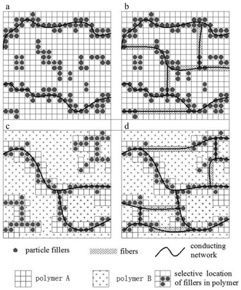
  • In the simplest case, when a single filler (either spherical particles or fibers) is dispersed into a single polymer matrix, the contact between the filler particles/fibers is reached at the percolation threshold and can be maximized by increasing the filler concentration above the percolation threshold (Figure 6, Panel A).
  • If dual fillers (both spherical particles and fibers) are dispersed into a single polymer matrix, fibrous fillers connect the islands of granular fillers (short-distance conductivity), thus extending the connectivity (long-distance conductivity) of the network and consequently extending the electrically conductive network (Figure 6, Panel B).
  • A single filler (either spherical particles or fibers) dispersed into a blend of two immiscible polymers may interact differently with the two polymeric matrices, causing the formation of a conductive network either within a particular polymer phase or at the interface between the two immiscible polymers. This may result in the formation of a filler-rich polymeric phase. To be electrically conductive, these composites require a rich phase of fillers forming a continuous phase [100] (Figure 6, Panel C).
  • Dual fillers (both spherical particles and fibers) are dispersed into a blend of two immiscible polymers. The related systems show relevant bridging effects, low percolation threshold, and high conductivity (Figure 6, Panel D).
However, the introduction of inorganic fillers into polymeric matrices not only influences the electrical and thermal properties (i.e., the increment of metal content enhances the thermal conductivity in the composite) but also affects the final mechanical properties. In fact, the introduction of a higher quantity of inorganic filler causes a significant improvement in the rigidity and resistance of composites with a consequent increment of the Young modulus, tensile, and flexural strength, coupled with a reduction of the elongation at break and time to break [101]. Additionally, higher content of inorganic filler increases the hardness of the composite surface [101]. Nevertheless, the filler fraction increment affects the composite density as a consequence of the reduced interparticle distance and voids fraction. In the case of metallic fillers, it increases the composite density proportionally to the filler content, ranging from the value of a bare polymeric matrix (0% metal, 100% polymer) to one of the bare metals (100% metal, 0% polymer), following the rule of mixtures.
It is important to note that also polymeric matrices can affect the composite electrical conductivity since the filler–matrix interaction at the interfacial region plays an important role in either favoring or penalizing the electrical conductivity within the final material [101,102].

5. A Survey on the Chemical Nature of Fillers for ESD Composites from the Inorganic Chemistry Viewpoint

On the basis of the chemical nature, conductive fillers for ESD materials can be classified into five categories, as reported in Figure 7, which are: (i) metallic fillers as particles, flakes, and nanowires, (ii) carbonaceous materials, (iii) ceramic fillers, (iv) intrinsic conductive polymers (e.g., polyaniline, polypyrrole), and (v) metal-coated fillers [15,18,96,103,104,105,106,107]. The metal-coated fillers category can be organized into either metal-core or nonmetal-core fillers. The first one belongs to the metallic filler’s subgroup, whereas the second one comprises carbonaceous, ceramic, polymeric, and glass fillers covered by a conductive metallic coating. However, only intrinsically inorganic fillers are considered in the following discussion, thus belonging to the classes of metals, carbonaceous materials, and ceramics.
Metallic fillers forming ESD composites are mainly made of nanoscopic silver (Ag), copper (Cu), aluminum (Al), gold (Au), and nickel (Ni). Among these, the use of Ag guarantees several advantages since it shows great electrical and thermal conductivity with a consequently very low percolation threshold [107], can be synthesized under different shapes (such as spherical particles, flakes, rods, flowers-like particles, and wires) [108,109,110,111], and is very appealing due to its relevant antimicrobial response [112,113]. On the other hand, Cu possesses high electrical and thermal conductivity, showing good migration of electrons capability [107,114], although it oxidizes at mild thermal and moisture conditions, thus requiring a surface coating deposition with another conductive metal (e.g., Ag). Several literature studies report the possibility of using Al as a conductive filler since it shows great electrical and thermal conductivity due to its high intrinsic electrical conductivity, coupled with a relatively low cost compared to the previously discussed precious metals [115]. Even if the use of metallic fillers in ESD composites is effective from the electrical properties’ viewpoint, there are several health and environmental concerns to face due to potential uncontrolled metal release during the ESD composites product life [116].
The second relevant category relies on carbonaceous fillers such as carbon black (0D), carbon nanotubes (CNTs, 1D), graphite/graphene (and related materials, 2D), and carbon nanofibers (CNFs), having exceptionally high electrical and thermal conductivity when particles are at the nanoscopic level (i.e., when they present high aspect ratio) [117,118,119]. The most efficient conductive fillers belonging to this category are CNTs and CNFs. CNTs (both single-walled and multiwalled) possess excellent electrical and thermal conductivity (even higher than metals), coupled with a high aspect ratio (ca. 1000) that guarantees a very low percolation threshold (i.e., the percolation threshold is inversely proportional to the filler aspect ratio). The main issue for the preparation of CNTs-filled ESD composites is the low dispersion of CNTs within the polymeric matrix, as they tend to aggregate [119,120]. Compared to CNTs, CNFs (with aspect ratio ca. >100) are a promising low-cost alternative (i.e., CNFs are 3–10 order of magnitude cheaper than CNTs) with outstanding electrical and thermal properties [107,121]. Moreover, graphene (which is a monolayer exfoliated from graphite layers) possesses interesting electrical/thermal (and mechanical) properties as it is able to form a conductive filler network with a low percolation threshold [122]. However, analogously to CNTs, graphene might be affected by a low distribution in the composite [107]. An alternative to graphene is graphite, which is the thermodynamically stable allotropic form of C, made by multiple layers of graphene. Both in graphene and graphite, the electrical charges follow the direction of the basal plane, whereas they result insulant in the direction normal to the basal plane. This means that the electrical properties in graphene and graphite vary according to the number of available graphene sheets [123]. Finally, yet importantly, among the possible alternative conductive carbonaceous fillers is carbon black, a paracrystalline C-containing material obtained from the uncompleted combustion/decomposition of hydrocarbons [107,124,125]. Both the intrinsic electrical and thermal conductivity of carbon black are strongly affected by its surface area and porosity, structure, and presence of residual functionalities. In carbon black, electrical tunneling is the dominant electrical mechanism, which involves the electrical current flowing between the carbon black clusters that are closely located, jumping the insulant matrix comprised in between [126]. Interestingly, this led to an important increase in the electrical conductivity in carbon-black-filled composites if the material is subjected to mechanical compression, as compression causes a reduction of the filler–filler distance within the composite [126]. Carbonaceous fillers are also an interesting test bed for evaluating the role played by the filler geometry in affecting the conductive network path. Following the density of state theory, the electron motion is confined along three, two, or a single spatial direction, in 0D, 1D, and 2D nanomaterials, respectively. This assumption justifies the predominant efficiency of 2D nanomaterials, where the electron motion is confined along one direction over the other two categories (i.e., 0D and 1D materials) [127]. In particular, according to the literature, it emerges that the conductive path in the case of 0D nanomaterials (e.g., carbon black) is mainly driven by electrical tunneling, whereas in the case of 1D nanomaterials (e.g., CNTs), conduction is driven by both electrical tunneling and direct filler–filler contact (i.e., filler network formation) [128]. As previously discussed, two-dimensional nanomaterials (e.g., graphene), instead, exhibit an electrical anisotropy depending on the basal plane direction [129], thus making it more driven by the filler–filler interaction. Additionally, the filler geometry affects the percolation threshold as the higher the aspect ratio, the lower the percolation threshold.
The last class of inorganic fillers considered here is ceramic ones. According to the IUPAC definition, the term “ceramic” refers to inorganic crystalline compounds comprising metallic atoms bonded to nonmetallic ones (e.g., metal oxides, borides, nitrides, and carbides) [130]. Ceramic fillers showing conductive features are for instance BN, TiB, TiB2, SiC, ITO (indium tin oxide), and many others [131,132,133,134,135]. Since several ceramic fillers behave as semiconductors, this class of inorganic fillers is mostly used as secondary fillers, coupled with a primary filler showing intrinsic conductivity and belonging to the previous two categories (either metallic or carbonaceous species). The main advantage of ceramic compounds as secondary fillers is the reduction of the amount of the primary filler, coupled with an increment in terms of inorganic structure compactness, thus facilitating the formation of the conductive filler network. Furthermore, since ceramics present high values of Young modulus (stiffness), tensile strength, hardness, and a high melting point, the introduction of ceramic fillers in a polymeric matrix enhances the final composite hardness and brittleness with a high resistance under compression and a low resistance under tensile and shear stress. Furthermore, the use of ceramic fillers guarantees an increment of the stability of the composite toward oxidation, and, consequently, of the electrical conductivity in contrast to metallic fillers which are sensible to oxidation [132].

6. Actual Technological Solutions

The technological and economic interest in novel static-dissipative and antistatic composites for preventing the occurrence of uncontrolled ESD phenomena is becoming a rapidly increasing field of interest. The analysis of the market for these composites is quite broad covering many aspects of the working life of both operators and industrial processes. Surely, the main relevant part of this market is related to ESD-safe clothing and tools (some examples of ESD objects can be found in [136]).
Concerning the role of ESD formulation in clothing, the market proposes a multitude of different objects made by ESD fabrics exploitable in many industrial uses. Some examples can be clothes for dust-free environments (i.e., cleanroom), such as factory work shirts, antistatic aprons, and shawl caps, which are typically made of polymeric fabrics (e.g., polyester) and carbon fibers (<2%). In the case of touch screen systems, both gloves and thumb finger sleeves must be conductive but frictionless (to avoid triboelectric charging), and they are typically made of polymeric fibers mixed with carbon filaments or metal (Cu, Ag) fibers. In general, static dissipative/conductive fibers for ESD applications are mainly made of synthetic fibers with either a carbon core or a carbon coating [137]. Sometimes, in the case of antistatic systems, the polymeric fabrics (independently from their chemical nature) are simply woven with carbon fibers forming a parallel arrangement or mesh pattern. Interestingly, ESD materials are also used for antistatic surfaces, such as rubber mats for covering tables and floors or working shoes. In particular, rubber mats are designed with a conductive bottom layer to eliminate static electricity [138].
The other major field where ESD composites find their actual applications is the handling/packaging of electronics and other objects sensitive to static electricity (e.g., automotive components and batteries) [139]. In the case of industrial packaging, there are several examples of antistatic flexible films, foams, and rigid sheets made by different polymeric matrices (e.g., PE, PP, PVC, ABS, PMMA, PET, EVA, PC, TPU, and PLA) with proper additives (mainly carbonaceous fillers but also metalized (mainly Al) coatings) to be used for covering surfaces or in direct contact with electronics devices. In particular, antistatic bags are typically made of PET and show distinctive colors depending on the filler, namely, transparent when ITO is used, silver in the case of metalized films, black for systems containing a carbonaceous filler, and pink due to the presence of long-chain amines/amides or other dissipative agents [140].
For the electronics components, ESD protective formulation can be 3D printed to form tools (e.g., jigs, fixtures, and working supports) able to safely divert static electricity away from sensitive electrical parts during manufacturing or testing [141]. In this case, typical conductive fillers introduced in such formulations are carbonaceous fillers, such as carbon black, CNTs, and graphite. The production of such ESD composites requires starting from the preparation of masterbatch pellets containing a high amount of conductive fillers (mostly carbonaceous ones) and progressively diluting the concentration of the filler by adding more polymer during processing in order to modulate the electric response in the final extruded material, ranging from conductive to antistatic formulations. Even if this approach seems quite simple, the technological interest in electrically conductive and ESD materials is still growing as testified by the recent literature [142,143,144,145,146,147,148,149,150].

7. Conclusions and Perspectives

This review reports the main features concerning the accumulation of static electricity and critically analyzes the consequent electrostatic discharge (ESD) phenomena. The electric phenomenon is the basis of several damages and failures occurring in integrated electronic and microelectronic devices, becoming a potential source of serious hazards to human health during processes and storage. To overcome this underestimated issue, the development of ESD protection systems made by dispersing conductive fillers into insulant matrices is attracting the attention of worldwide experts in different fields. With the aim of providing a practical guide, a phenomenological description of the four different mechanisms of formation of electrostatic charges at the surface of materials was here reported, providing a deep analysis of the causes for the occurrence of charging phenomena. Secondly, the classification of ESD materials according to their electrical properties has been provided together with a description of the more diffused methods for determining electrical properties (i.e., surface and volumetric resistivity) in ESD composites. Differences between conductive, static-dissipative, and antistatic composites were clarified. The standard human body model (HMB) has been presented as a method for evaluating the protective capability of ESD formulations relative to persons/objects against the occurrence of undesired (and abrupt) ESD phenomena. Furthermore, a description of the methods for favoring the transition of electric charges within composites, the role of conductive fillers in the formation of a filler network, and the different mechanisms for the movement of the electric charge are discussed. A paragraph dedicated to the actual market of these ESD composites has been included in the discussion. Lastly, an overview of the different classes of conductive fillers (in particular, inorganic species) has been provided, evidencing the pros/cons and criticalities of each category of inorganic fillers.
This study evidences how the research on inorganic fillers for the development of advanced composites passes not only for the capability of enhancing the mechanical performances, but also in exerting a certain level of control of the physicochemical properties (i.e., electrical conductivity) in composites, as in the case of ESD materials. In this context, it is mandatory to find formulations able to either slow down the flow of electric charges (static-dissipative) or directly suppress the initial charges induced by charging phenomena (antistatic). Fields of interest in ESD materials range from personal protective equipments for operators, clothes and accessories, structural protective materials, devices exploitable in industrial processes, electronics, and microelectronics to the packaging industry and many others. Several technological solutions are reported, but the analysis of the actual market pointed out that carbonaceous fillers play a predominant role among the other conductive additives. The reasons are probably the large variety of shapes and geometries, their high compatibility with the polymeric matrices, and their organic nature, which favors their end-of-life fate (i.e., polymeric composites containing carbonaceous fillers can be thermally treated to recover energy). In the case of either coated surfaces or woven fabrics, together with carbonaceous fillers, metallic fillers (mostly Cu, Ag, and Al) are also exploitable solutions. Among the inorganic fillers, ceramics are poorly used in ESD applications. The only exception is the use of ITO when it is mandatory to maintain transparency, such as in the case of polymeric films for packaging.
However, as discussed in the text, the future of ESD composite materials is not only driven by the selection of the best conductive filler, but it is also strongly influenced by the engineering of the filler network. In fact, according to the present authors, the filler concentration and percolation threshold are key parameters that have to be taken into account. In particular, higher content of inorganic filler means not only higher conductivity, but also an increment of the stiffness of the composite, thus affecting the processability and molding technique of the mechanical performances. To solve this issue, the compatibilization of inorganic fillers will play a fundamental role in minimizing the dispersion of the fillers within the matrix (thus avoiding clusterization and segregation), still maintaining electrical properties unaltered. The recent literature points out that the surface chemical modification of inorganic fillers favors their dispersion in polymeric matrices [151,152]. However, in the case of electrical conductivity, this is not immediately obvious, as electrical conduction is also a surface phenomenon. Therefore, the only way to overcome this situation is to try to maximize the comprehension of surface-related interactions and phenomena occurring between filler–filler and filler–matrix and to look for novel advanced formulations to counteract the occurrence of uncontrolled ESD phenomena.

Author Contributions

Conceptualization, R.N.; writing—original draft preparation, R.N.; writing—review and editing, R.N., M.D., B.D.C., S.M., R.S.; supervision, M.D., R.S. All authors have read and agreed to the published version of the manuscript.

Funding

This research received no external funding.

Conflicts of Interest

The authors declare no conflict of interest.

References

  1. Voldman, S.H. ESD: Physics and Devices; Wiley: Hoboken, NY, USA, 2004; ISBN 978-0-4708-4753-4. [Google Scholar]
  2. Kaiser, K.L. Electrostatic Discharge; CRC Press, Taylor & Francis Group: Boca Raton, FL, USA, 2006; ISBN 978-0-8493-7188-2. [Google Scholar]
  3. Jonassen, N. Electrostatics; Springer Science & Business Media: Boston, MA, USA, 1998; ISBN 978-0-4757-1184-4. [Google Scholar]
  4. Voldman, S.H. A review of electrostatic discharge (ESD) in advanced semiconductor technology. Microelectron. Reliab. 2004, 44, 33–46. [Google Scholar] [CrossRef]
  5. Semenov, O.; Somov, S. ESD protection design for I/O libraries in advanced CMOS technologies. Solid State Electron. 2008, 52, 1127–1139. [Google Scholar] [CrossRef]
  6. Smallwood, J. ESD in industry—Present and future. J. Phys. Conf. Ser. 2015, 646, 012018. [Google Scholar] [CrossRef]
  7. Okoniewska, E.; Stuchly, M.A.; Okoniewski, M. Interactions of electrostatic discharge with the human body. IEEE T Microw. Theory 2004, 52, 2030–2039. [Google Scholar] [CrossRef]
  8. Wang, A.Z.; Feng, H.G.; Gong, K.; Zhan, R.Y.; Stine, J. On-chip ESD protection design for integrated circuits: An overview for IC designers. Microelectron. J. 2001, 32, 733–747. [Google Scholar] [CrossRef]
  9. ESDA.org. Available online: https://www.esda.org (accessed on 14 January 2020).
  10. Incompliancemag.com. Fundamentals of Electrostatic Discharge Part One—An introduction to ESD. Available online: https://incompliancemag.com/article/fundamentals-of-electrostatic-discharge-part-one-an-introduction-to-esd/ (accessed on 29 April 2020).
  11. Voldman, S.H. Evolution, revolution, and technology scaling—The impact on ESD and EOS reliability. Front. Mater. 2018, 5, 33. [Google Scholar] [CrossRef]
  12. Hu, Y.; Wang, D.; Liu, J.; Gao, J. A case study of the electrostatic accidents in the process of oil-gas storage and transportation. J. Phys. Conf. Ser. 2013, 418, 012037. [Google Scholar] [CrossRef]
  13. Choi, K.; Sakasai, H.; Nishimura, L. Experimental study on the ignitability of pure aluminum powders due to electrostatic discharge and nitrogen’s effect. J. Loss Prevent. Proc. 2015, 35, 232–235. [Google Scholar] [CrossRef]
  14. Wu, Z.; Chen, Y.; Hu, X.; Liu, S. Research on ESD ignition hazards of textiles. J. Electrostat. 2003, 57, 203–207. [Google Scholar] [CrossRef]
  15. Ge, C.; Cosgrove, K. Preparation of PVOH coatings with graphene nanoplatelets for electrostatics discharge protective packaging. J. Electrostat. 2015, 77, 157–162. [Google Scholar] [CrossRef]
  16. Koul, S.; Chandra, R.; Dhawan, S.K. Conducting polyaniline composite for ESD and EMI at 101 GHz. Polymer 2000, 41, 9305–9310. [Google Scholar] [CrossRef]
  17. Tsurumaki, A.; Tajima, S.; Iwata, T.; Scrosati, B.; Ohno, H. Antistatic effects of ionic liquids for polyether-based polyurethanes. Electrochim. Acta 2015, 175, 13–17. [Google Scholar] [CrossRef]
  18. Narkis, M.; Lidor, G.; Vaxman, A.; Zuri, L. New injectable moldable electrostatic dissipative (ESD) composites based on very low carbon black loadings. J. Electrostat. 1999, 47, 201–214. [Google Scholar] [CrossRef]
  19. Wang, C.X.; Lv, J.C.; Ren, Y.; Zhi, T.; Chen, J.Y.; Zhou, Q.Q.; Lu, Z.Q.; Gao, D.W.; Jin, L.M. Surface modification of polyester fabric with plasma pretreatment and carbon nanotube coating for antistatic property improvement. Appl. Surf. Sci. 2015, 359, 196–203. [Google Scholar] [CrossRef]
  20. Li, C.; Liang, T.; Lu, W.; Tang, C.; Hu, X.; Cao, M.; Liang, J. Improving the antistatic ability of polypropylene fibers by inner antistatic agent filled with carbon nanotubes. Compos. Sci. Technol. 2004, 64, 2089–2096. [Google Scholar] [CrossRef]
  21. Dharmasena, R.D.I.G.; Silva, S.R.P. Towards optimized triboelectric nanogenerators. Nano Energy 2019, 62, 530–549. [Google Scholar] [CrossRef]
  22. Chen, J.; Qiu, Q.; Han, Y.; Lau, D. Piezoelectric materials for sustainable building structures: Fundamentals and applications. Renew. Sust. Energ. Rev. 2019, 101, 14–25. [Google Scholar] [CrossRef]
  23. Zabek, D.; Morini, F. Solid state generators and energy harvesters for waste heat recovery and thermal energy harvesting. Therm. Sci. Eng. Prog. 2019, 9, 235–247. [Google Scholar] [CrossRef]
  24. Yang, X.; Xu, C.; Kunieda, M. Miniaturization of WEDM using electrostatic induction feeding method. Precis. Eng. 2010, 34, 279–285. [Google Scholar] [CrossRef]
  25. McCarty, L.S.; Whitesides, G.M. Electrostatic charging due to separation of ions at interfaces: Contact electrification of ionic electrets. Angew. Chem. Int. Ed. 2008, 47, 2188–2207. [Google Scholar] [CrossRef]
  26. Galembeck, F.; Burgo, T.A.L.; Balestrin, L.B.S.; Gouveia, R.F.; Silva, C.A.; Galembeck, A. Friction, tribochemistry, and triboelectricity: Recent progress and perspectives. RSC Adv. 2014, 4, 64280–64298. [Google Scholar] [CrossRef]
  27. Freeman, G.R.; March, N.H. Triboelectricity and some associated phenomena. Mater. Sci. Technol. 1999, 15, 1454–1458. [Google Scholar] [CrossRef]
  28. Matsusaka, S.; Maruyama, H.; Matsuyama, T.; Ghadiri, M. Triboelectric charging of powders: A review. Chem. Eng. Sci. 2010, 65, 5781–5807. [Google Scholar] [CrossRef] [Green Version]
  29. Zou, H.; Zhang, Y.; Guo, L.; Wang, P.; He, X.; Dai, G.; Zheng, H.; Chen, C.; Wang, A.C.; Xu, C.; et al. Quantifying the triboelectric series. Nat. Commun. 2019, 10, 1427. [Google Scholar] [CrossRef] [Green Version]
  30. Diaz, A.F.; Felix-Navarro, R.M. A semi-quantitative tribo-electric series for polymeric materials: The influence of chemical structure and properties. J. Electrostat. 2004, 62, 277–290. [Google Scholar] [CrossRef]
  31. Henniker, J. Triboelectricity in polymers. Nature 1962, 196, 474. [Google Scholar] [CrossRef]
  32. Kim, W.; Bhatia, D.; Hwang, H.J.; Choi, K.; Choi, D. Double impact triboelectric nanogenerators for harvesting broadband vibrations from vehicles. Funct. Compos. Struct. 2019, 1, 035003. [Google Scholar] [CrossRef]
  33. Xu, M.; Zhao, T.; Wang, C.; Zhang, S.L.; Li, Z.; Pan, X.; Wang, Z.L. High power density tower-like triboelectric nanogenerator for harvesting arbitrary directional water wave energy. ACS Nano 2019, 13, 1932–1939. [Google Scholar] [CrossRef]
  34. Feng, Y.; Zhang, L.; Zheng, Y.; Wang, D.; Zhou, F.; Liu, W. Leaves based triboelectric nanogenerator (TENG) and TENG tree for wind energy harvesting. Nano Energy 2019, 55, 260–268. [Google Scholar] [CrossRef]
  35. Xia, K.; Zhu, Z.; Zhang, H.; Du, C.; Fu, J.; Xu, Z. Milk-based triboelectric nanogenerator on paper for harvesting energy from human body motion. Nano Energy 2019, 56, 400–410. [Google Scholar] [CrossRef]
  36. Zheng, Q.; Shi, B.; Li, Z.; Wang, Z.L. Recent progress on piezoelectric and triboelectric energy harvesters in biomedical systems. Adv. Sci. 2017, 4, 1700029. [Google Scholar] [CrossRef]
  37. Americanpiezo.com. Piezoelectricity. Available online: https://www.americanpiezo.com/knowledge-center/piezo-theory/piezoelectricity.html (accessed on 29 April 2020).
  38. Goel, S.; Kumar, B. A review on piezo-/ferro-electric properties of morphologically diverse ZnO nanostructures. J. Alloys Compd. 2010, 816, 152491. [Google Scholar] [CrossRef]
  39. Song, R.; Zhao, Y.; Li, W.; Yu, Y.; Sheng, J.; Li, Z.; Zhang, Y.; Xia, H.; Fei, W.-D. High temperature stability and mechanically quality factor of donor-acceptor co-doped BaTiO3 piezoelectrics. Acta Mater. 2019, 181, 200–206. [Google Scholar] [CrossRef]
  40. Hao, J.; Li, W.; Zhai, J.; Chen, H. Progress in high-strain perovskite piezoelectric ceramics. Mater. Sci. Eng. R. 2019, 135, 1–57. [Google Scholar] [CrossRef]
  41. Zhang, Y.; Sun, H.; Chen, W. A brief review of Ba(Ti0.8Zr0.2)O3-(Ba0.7Ca0.3)TiO3 based lead-free piezoelectric ceramics: Past, present and future perspectives. J. Phys. Chem. Solids 2018, 114, 207–219. [Google Scholar] [CrossRef]
  42. Li, J.; Long, Y.; Yang, F.; Wang, X. Degradable piezoelectric biomaterials for wearable and implantable bioelectronics. Curr. Opin. Solid State Mater. Sci. 2020, 24, 100806. [Google Scholar] [CrossRef]
  43. Street, R.M.; Huseynova, T.; Xu, X.; Chandrasekaran, P.; Han, L.; Shih, W.Y.; Shih, W.-H.; Schauer, C.L. Variable piezoelectricity of electrospun chitin. Carbohydr. Polym. 2018, 195, 218–224. [Google Scholar] [CrossRef]
  44. Yang, Y.; Pan, H.; Xie, G.; Jiang, Y.; Chen, C.; Su, Y.; Wang, Y.; Tai, H. Flexible piezoelectric pressure sensor based on polydopamine-modified BaTiO3/PVDF composite film for human motion monitoring. Sens. Actuator A Phys. 2020, 301, 111789. [Google Scholar] [CrossRef]
  45. Sinar, D.; Knopf, G.K. Disposable piezoelectric vibration sensors with PDMS/ZnO transducers on printed graphene-cellulose electrodes. Sens. Actuator A Phys. 2020, 302, 111800. [Google Scholar] [CrossRef]
  46. Ejeian, F.; Azadi, S.; Razmjou, A.; Orooji, Y.; Kottapalli, A.; Warkiani, M.E.; Asadnia, M. Design and applications of MEMS flow sensors: A review. Sens. Actuator A Phys. 2019, 295, 483–502. [Google Scholar] [CrossRef]
  47. Tiller, B.; Reid, A.; Zhu, B.; Guerreiro, J.; Domingo-Roca, R.; Jackson, J.C.; Windmill, J.F.C. Piezoelectric microphone via a digital light processing 3D printing process. Mater. Des. 2019, 165, 107593. [Google Scholar] [CrossRef]
  48. Ezzhra-Bouharras, F.; Raihane, M.; Ameduri, B. Recent progress on core-shell structured BaTiO3@polymer/fluorinated polymers nanocomposites for high energy storage: Synthesis, dielectric properties and applications. Prog. Mater. Sci. 2020, 113, 100670. [Google Scholar] [CrossRef]
  49. Ali, F.; Raza, W.; Li, X.; Gul, H.; Kim, K.-H. Piezoelectric energy harvesters for biomedical applications. Nano Energy 2019, 57, 879–902. [Google Scholar] [CrossRef]
  50. Tandon, B.; Blaker, J.J.; Cartmell, S.H. Piezoelectric materials as stimulatory biomedical materials and scaffolds for bone repair. Acta Biomater. 2018, 73, 1–20. [Google Scholar] [CrossRef] [Green Version]
  51. Rajabi, A.H.; Jaffe, M.; Arinzeh, T.L. Piezoelectric materials for tissue regeneration: A review. Acta Biomater. 2015, 24, 12–23. [Google Scholar] [CrossRef] [Green Version]
  52. Lagerwall, S.T. Ferroelectric and antiferroelectric liquid crystals. In Encyclopedia of Materials: Science and Technology, 2nd ed.; Buschow, J., Cahn, R.W., Flemings, M.C., Ilschner, B., Kramer, E.J., Mahajan, S., Veyssiere, P., Eds.; Pergamon Press: Oxford, UK, 2001; pp. 3044–3063. ISBN 978-0-08-043152-9. [Google Scholar] [CrossRef]
  53. Damjanovic, D. Ferroelectric dielectric and piezoelectric properties of ferroelectric thin films in ceramics. Rep. Prog. Phys. 1998, 61, 1267–1324. [Google Scholar] [CrossRef] [Green Version]
  54. Kao, K.C. 2—Electric polarization and relaxation. In Dielectric Phenomena in Solids, with Emphasis on Physical Concepts of Electronic Processes; Kao, K.C., Ed.; Academic Press: San Diego, CA, USA, 2004; pp. 41–114. ISBN 0-12-396561-9780123965615. [Google Scholar] [CrossRef]
  55. Nisticò, R.; Cesano, F.; Garello, F. Magnetic materials and systems: Domain structure visualization and other characterization techniques for the application in the materials science and biomedicine. Inorganics 2020, 8, 6. [Google Scholar] [CrossRef] [Green Version]
  56. Nisticò, R. Magnetic materials and water treatments for a sustainable future. Res. Chem. Intermed. 2017, 43, 6911–6949. [Google Scholar] [CrossRef]
  57. Stojanovic, B.D. Introduction to ferroics and multiferroics: Essential background. In Magnetic, Ferroelectric, and Multiferroic Metal Oxides; Stojanovic, B.D., Ed.; Elsevier: Amsterdam, The Netherlands, 2018; pp. xxxi–xlii. ISBN 978-0-12-811180-2. [Google Scholar] [CrossRef]
  58. Maiwa, H. 12—Thermal energy harvesting of PLZT and BaTiO3 ceramics using pyroelectric effects. In Nanoscale Ferroelectric-Multiferroic Materials for Energy Harvesting Applications; Kimura, H., Cheng, Z., Jia, T., Eds.; Elsevier: Amsterdam, The Netherlands, 2019; pp. 217–229. ISBN 978-0-12-814499-2. [Google Scholar] [CrossRef]
  59. Li, J.; Li, J.; Cheng, X.; Feng, G. Investigation of induced charge mechanisms on a rod electrode. Electronics 2019, 8, 977. [Google Scholar] [CrossRef] [Green Version]
  60. Zhao, S.; Castle, G.S.P.; Adamial, K. Comparison of conduction and induction charging in liquid spraying. J. Electrostat. 2005, 63, 871–876. [Google Scholar] [CrossRef]
  61. Salome, P.; Rochier, C. Electrostatic discharges (ESD), latch-up and pad design constraints. Microelectron. Eng. 1999, 49, 83–94. [Google Scholar] [CrossRef]
  62. Ye, H.; Wang, Q.; Sun, Q.; Xu, L. High energy density and interfacial polarization on poly(vinylidene fluoride-chlorotrifluoroethylene) nanocomposite incorporated with halloysite nanotube architecture. Colloids Surf. A Physicochem. Eng. Asp. 2020, 606, 125495. [Google Scholar] [CrossRef]
  63. Heinert, C.; Sankaran, R.M.; Lacks, D.J. Electrostatic charge generation on material surface from the evaporation of liquids. J. Electrostat. 2020, 105, 103450. [Google Scholar] [CrossRef]
  64. Kok, J.F.; Renno, N.O. Enhancement of the emission of mineral dust aerosols by electric forces. Geophys. Res. Lett. 2006, 33, L19S10. [Google Scholar] [CrossRef] [Green Version]
  65. Yadav, R.; Tirumali, M.; Wang, X.; Naebe, M.; Kandasubramanian, B. Polymer composite for antistatic application in aerospace. Def. Technol. 2020, 16, 107–118. [Google Scholar] [CrossRef]
  66. Sugo ESD Plastics. ESD Materials Categories. Available online: http://en.sugoplas.com/news/industry/95.html (accessed on 27 February 2021).
  67. Markarian, J. New developments in antistatic and conductive additives. Plast. Addit. Compd. 2008, 10, 22–25. [Google Scholar] [CrossRef]
  68. Zhang, R.; Agar, J.C.; Wong, C.P. Conductive polymer composites. In Encyclopedia of Polymer Science and Technology; John Wiley and Sons: Hoboken, NJ, USA, 2011. [Google Scholar] [CrossRef]
  69. Amoabeng, D.; Velankar, S.S. A review of conductive polymer composites filled with low melting point metal alloys. Polym. Eng. Sci. 2018, 58, 1010–1019. [Google Scholar] [CrossRef] [Green Version]
  70. Meenach, S.A.; Burdick, J.; Kunwar, A.; Wang, J. Metal/conducting-polymer composite nanowires. Small 2007, 3, 239–243. [Google Scholar] [CrossRef]
  71. Wang, M.; Tang, X.-H.; Cai, J.-H.; Wu, H.; Shen, J.-B.; Guo, S.-Y. Construction, mechanism and prospective of conductive polymer composites with multiple interfaces for electromagnetic interface shielding: A review. Carbon 2021, 177, 377–402. [Google Scholar] [CrossRef]
  72. Kondrashov, S.V.; Soldatov, M.A.; Gunyaeva, A.G.; Shashkeev, K.A.; Komarova, O.K.; Barinov, D.Y.; Yurkov, G.Y.; Shevchenko, V.G.; Muzafarov, A.M. The use of noncovalently modified carbon nanotubes for preparation of hybrid polymeric composite materials with electrically conductive and lightning resistant properties. J. Appl. Polym. Sci. 2018, 135, 46108. [Google Scholar] [CrossRef]
  73. Clingerman, M.L.; Weber, E.H.; King, J.A.; Schulz, K.H. Synergistic effect of carbon filler in electrically conductive nylon 6,6 and polycarbonate based resins. Polym. Compos. 2002, 23, 911–924. [Google Scholar] [CrossRef]
  74. Wang, P.; Ding, T. Conductivity and piezoresistivity of conductive carbon black filled polymer composite. J. Appl. Polym. Sci. 2010, 116, 2035–2039. [Google Scholar] [CrossRef]
  75. Ning, W.; Xingxiang, Z.; Jiugao, Y.; Jianming, F. Partially miscible poly(lactic acid)-blend-poly(propylene carbonate) filled with carbon black as conductive polymer composite. Polym. Int. 2008, 57, 1027–1035. [Google Scholar] [CrossRef]
  76. Cataldi, P.; Bayer, I.S.; Bonaccorso, F.; Pellegrini, V.; Athanassiou, A.; Cingolani, R. Foldable conductive cellulose fiber networks modified by graphene nanoplatelet bio-based composites. Adv. Electron. Mater. 2015, 1, 1500224. [Google Scholar] [CrossRef]
  77. Yang, S.; Chalivendra, V.; Benjamin, E.; Kim, Y. Electrical response of novel carbon nanotubes embedded and carbon fiber Z-axis reinforced jute/epoxy laminated composites. Polym. Compos. 2019, 40, E1189–E1198. [Google Scholar] [CrossRef]
  78. Syurik, Y.V.; Ghislandi, M.G.; Tkalya, E.E.; Paterson, G.; McGrouther, D.; Ageev, O.A.; Loos, J. Graphene network organization in conductive polymer composites. Macromol. Chem. Phys. 2012, 213, 1251–1258. [Google Scholar] [CrossRef]
  79. Dos Santos, A.M.; Merlini, C.; Ramoa, S.D.A.S.; Barra, G.M.O. Comparative study of electrically conductive polymer composites of polyester-based thermoplastic polyurethane matrix with polypyrrole and montmorillonite/polypyrrole additive. Polym. Compos. 2020, 41, 2003–2012. [Google Scholar] [CrossRef]
  80. Hansen, T.S.; West, K.; Hassanger, O.; Larsen, N.B. Highly stretchable and conductive polymer material made from poly(3,4-ethylenedioxythiophene) and polyurethane elastomers. Adv. Funct. Mater. 2007, 17, 3069–3073. [Google Scholar] [CrossRef]
  81. Shankar, U.; Bhandari, S.; Khastgir, D. Carbon black-filled nitrile rubber composite as a flexible electrode for electrochemical synthesis of supercapacitive polyaniline. Polym. Compos. 2019, 40, E1537–E1547. [Google Scholar] [CrossRef]
  82. Omastova, M.; Pavlinec, J.; Pionteck, J.; Simon, F. Synthesis, electrical properties and stability of polypyrrole-containing conducting polymer composites. Polym. Int. 1997, 43, 109–116. [Google Scholar] [CrossRef]
  83. Kosinski, S.; Rykowska, I.; Gonsior, M.; Krzyzanowski, P. Ionic liquids as antistatic additives for polymer composites—A review. Polym. Test. 2022, 112, 107649. [Google Scholar] [CrossRef]
  84. Plastucranger.com. Antistatic vs. Static Dissipative Plastics|Which One to Choose? Available online: https://plasticranger.com/antistatic-vs-dissipative-plastics/ (accessed on 21 June 2022).
  85. Reeves, G.K.; Leech, P.W.; Harrison, H.B. Understanding the sheet resistance parameter of alloyed ohmic contacts using a transmission line model. Solid State Electron. 1995, 38, 745–751. [Google Scholar] [CrossRef]
  86. Ausserlechner, U. Van-der-Pauw measurement on devices with four contacts and two orthogonal mirror symmetries. Solid State Electron. 2017, 133, 53–63. [Google Scholar] [CrossRef]
  87. Pveducation.org. Four Point Probe Resistivity Measurements. Available online: https://www.pveducation.org/pvcdrom/characterisation/four-point-probe-resistivity-measurements (accessed on 29 June 2022).
  88. Ossila.com. Sheet Resistance: A Guide to Theory. Available online: https://www.ossila.com/pages/sheet-resistance-theory (accessed on 29 June 2022).
  89. Singh, Y. Electrical Resistivity Measurements: A Review. Int. J. Mod. Phys. C 2013, 22, 745–756. [Google Scholar] [CrossRef]
  90. Embeddedcomputing.com. Fundamentals of HBM, MM, and CDM Tests by Bonnie Baker. Available online: https://embeddedcomputing.com/technology/analog-and-power/fundamentals-of-hbm-mm-and-cdm-tests#:~:text=The%20human-body%20model%20%28HBM%29%20characterizes%20an%20electronic%20device%E2%80%99s,ESD%29%20charges%20the%20capacitor%20in%20the%20test%20circuit (accessed on 27 June 2022).
  91. Electronicdesign.com. What’s the Difference between HBM, CDM, and MM Test? Available online: https://www.electronicdesign.com/power-management/article/21799383/whats-the-difference-between-hbm-cdm-and-mm-test (accessed on 27 June 2022).
  92. Brodbeck, T.; Gaertner, R. Experience in HBM ESD testing of high pin count devices. Microelectron. Reliab. 2007, 47, 1025–1029. [Google Scholar] [CrossRef]
  93. Meeder, M.G.; Marchut, L.; Antonell, M.J.; Fresina, M.T.; Novak, C.E.; Darche, T.C. Application of machine model ESD tester to high volume capacitor reliability testing. Microelectron. Reliab. 2011, 51, 246–251. [Google Scholar] [CrossRef]
  94. Greason, W.D. Analysis of charged device model (CDM) ESD in MEMS. J. Electrostat. 2010, 68, 159–167. [Google Scholar] [CrossRef]
  95. Tamminen, P.; Viheriakoski, T.; Sydanheimo, L.; Ukkonen, L. ESD qualification data used as the basis for building electrostatic discharge protected areas. J. Electrostat. 2015, 77, 174–181. [Google Scholar] [CrossRef]
  96. Sankaran, S.; Deshmukh, K.; Ahamed, M.B.; Pasha, S.K.K. Recent advances in electromagnetic interference shielding properties of metal and carbon filler reinforced flexible polymer composites: A review. Compos. A Appl. Sci. Manuf. 2018, 114, 49–71. [Google Scholar] [CrossRef]
  97. Al-Saleh, M.H.; Gelves, G.A.; Sundararaj, U. Copper nanowire/polystyrene nanocomposites: Lower percolation threshold and higher EMI shielding. Compos. A Appl. Sci. Manuf. 2011, 42, 92–97. [Google Scholar] [CrossRef]
  98. Folorunso, O.; Hamam, Y.; Sadiku, R.; Ray, S.S.; Kumar, N. Investigation and modeling of the electrical conductivity of graphene nanoplatelets-loaded doped pyrrole. Polymers 2021, 13, 1034. [Google Scholar] [CrossRef]
  99. Li, C.; Thostenson, E.T.; Chou, T.-W. Dominat role of tunnelling resistance in the electrical conductivity of carbon nanotube-based composites. Appl. Phys. Lett. 2007, 91, 223114. [Google Scholar] [CrossRef]
  100. Lou, C.-W.; Huang, C.-L.; Pan, Y.-J.; Lin, Z.-I.; Song, X.-M.; Lin, J.-H. Crystallization, mechanical, and electromagnetic properties of conductive polypropylene/SEBS composites. J. Polym. Res. 2016, 23, 84. [Google Scholar] [CrossRef]
  101. Adeniyi, A.G.; Ighalo, J.O. A systematic review of pure metals reinforced plastic composites. Iran. Polym. J. 2021, 30, 751–768. [Google Scholar] [CrossRef]
  102. Mamunya, Y.P.; Davydenko, V.V.; Pissis, P.; Lebedev, E.V. Electrical and thermal conductivity of polymers filled with metal powders. Eur. Polym. J. 2002, 38, 1887–1897. [Google Scholar] [CrossRef]
  103. Nassiet, V.; Hassoune-Rhabbour, B.; Tramis, O.; Petit, J.-A. 22—Electrical and Electronics. In Adhesive Bonding, Woodhead Publishing Series in Welding and Other Joining Technologies, 2nd ed.; Adams, R.D., Ed.; Woodhead Publishing: Duxford, UK, 2021; pp. 719–761. ISBN 9780128199541. [Google Scholar] [CrossRef]
  104. Fernandes, M.; Padrao, J.; Ribeiro, A.I.; Fernandes, R.D.V.; Melro, L.; Nicolau, T.; Mehravani, B.; Alves, C.; Rodrigues, R.; Zille, A. Polysaccharides and metal nanoparticles for functional textiles. A review. Nanomaterials 2022, 12, 1006. [Google Scholar] [CrossRef]
  105. Zhu, A.; Wang, H.; Sun, S.; Zhang, C. The synthesis and antistatic, anticorrosive properties of polyaniline composite coating. Prog. Org. Coat. 2018, 122, 270–279. [Google Scholar] [CrossRef]
  106. Thangamani, J.G.; Deshmukh, K.; Sadasivuni, K.K.; Ponnamma, D.; Goutham, S.; Rao, K.V.; Chidambaram, K.; Ahamed, M.B.; Grace, A.N.; Faisal, M.; et al. White graphene reinforced polypyrrole and poly(vinyl alcohol) blend nanocomposites as chemiresistive sensors for room temperature detection of liquid petroleum gases. Microchim. Acta 2017, 184, 3977–3987. [Google Scholar] [CrossRef]
  107. Aradhana, R.; Mohanty, S.; Nayak, S.K. A review on epoxy-based electrically conductive adhesives. Int. J. Adhes. Adhes. 2020, 99, 102596. [Google Scholar] [CrossRef]
  108. Chen, C.; Wang, L.; Yu, H.; Jiang, G.; Yang, Q.; Zhou, J.; Xiang, W.; Zhang, J. Study on the growth mechanism of silver nanorods in the nanowire-seeding polyol process. Mater. Chem. Phys. 2008, 107, 13–17. [Google Scholar] [CrossRef]
  109. Nisticò, R.; Rivolo, P.; Giorgis, F. Tips and tricks for the surface engineering of well-ordered morphologically driven silver-based nanomaterials. ChemistryOpen 2019, 8, 508–519. [Google Scholar] [CrossRef] [PubMed]
  110. Nisticò, R.; Barrasso, M.; Carrillo Le Roux, G.A.; Seckler, M.M.; Sousa, W.; Malandrino, M.; Magnacca, G. Biopolymers from composted biowaste as stabilizers for the synthesis of spherical and homogeneously sized silver nanoparticles for textile applications on natural fibers. ChemPhysChem 2015, 16, 3902–3909. [Google Scholar] [CrossRef] [PubMed]
  111. Nisticò, R.; Rivolo, P.; Novara, C.; Giorgis, F. New branched flower-like Ag nanostructures for SERS analysis. Colloids Surf. A Physicochem. Eng. Asp. 2019, 578, 123600. [Google Scholar] [CrossRef]
  112. Le Ouay, B.; Stellacci, F. Antibacterial activity of silver nanoparticles: A surface science insight. Nano Today 2015, 10, 339–354. [Google Scholar] [CrossRef]
  113. Nisticò, R.; Rosellini, A.; Rivolo, P.; Faga, M.G.; Lamberti, R.; Martorana, S.; Castellino, M.; Virga, A.; Mandracci, P.; Malandrino, M.; et al. Surface functionalisation of polypropylene hernia-repair meshes by RF-activated plasma polymerisation of acrylic acid and silver nanoparticles. Appl. Surf. Sci. 2015, 328, 287–295. [Google Scholar] [CrossRef]
  114. Abdulkareem, S.A.; Adeniyi, A.G. Recycling copper and polystyrene from solid waste stream in developing conductive composites. J. Solid Waste Technol. Manag. 2019, 45, 39–44. [Google Scholar] [CrossRef]
  115. Osman, A.F.; Mariatti, M. Properties of aluminum filled polypropylene composites. Polym. Polym. Compos. 2006, 14, 623–633. [Google Scholar] [CrossRef]
  116. Lu, S.; Gao, X.; Hu, C.-Y.; Xia, Y. Heavy metal release from irradiated LDPE/nanometal composite films into food stimulants. Food Packag. Shelf Life 2020, 26, 100571. [Google Scholar] [CrossRef]
  117. Spitalsky, Z.; Tasis, D.; Papagelis, K.; Galiotis, C. Carbon nanotube-polymer composites: Chemistry, processing, mechanical and electrical properties. Prog. Polym. Sci. 2010, 35, 357–401. [Google Scholar] [CrossRef]
  118. Jariwala, D.; Sangwan, V.K.; Lauhon, L.J.; Marks, T.J.; Hersam, M.C. Carbon nanomaterials for electronics, optoelectronics, photovoltaics, and sensing. Chem. Soc. Rev. 2013, 42, 2824–2860. [Google Scholar] [CrossRef] [Green Version]
  119. Lavagna, L.; Nisticò, R.; Musso, S.; Pavese, M. Functionalization as a way to enhance dispersion of carbon nanotubes in matrices: A review. Mater. Today Chem. 2021, 20, 100477. [Google Scholar] [CrossRef]
  120. Lavagna, L.; Marchisio, S.; Merlo, A.; Nisticò, R.; Pavese, M. Polyvinyl butyral-based composites with carbon nanotubes: Efficient dispersion as a key to high mechanical properties. Polym. Compos. 2020, 41, 3627–3637. [Google Scholar] [CrossRef]
  121. Ardanuy, M.; Rodriguez-Perez, M.A.; Algaba, I. Electrical conductivity and mechanical properties of vapor-grown carbon nanofibers/trifunctional epoxy composites prepared by direct mixing. Compos. B Eng. 2011, 42, 675–681. [Google Scholar] [CrossRef]
  122. Amoli, B.M.; Trinidad, J.; Rivers, G.; Sy, S.; Russo, P.; Yu, A.; Zhou, N.Y.; Zhao, B. SDS-stabilized graphene nanosheets for highly electrically conductive adhesives. Carbon 2015, 91, 188–199. [Google Scholar] [CrossRef]
  123. Khanam, P.N.; Ponnamma, D.; Al-Madeed, M.A. Electrical proeprties of graphene polymer nanocomposites. In Graphene-Based Polymer Nanocomposites in Electronics; Springer Series on Polymer and Composite Materials; Sadasivuni, K.K., Ponnamma, D., Kim, J., Thomas, S., Eds.; Springer International Publishing AG Switzerland: Cham, Switzerland, 2015; pp. 25–47. ISBN 978-3-3191-3874-9. [Google Scholar] [CrossRef]
  124. Boehm, H.P. Some aspects of the surface chemistry of carbon blacks and other carbons. Carbon 1994, 32, 759–769. [Google Scholar] [CrossRef]
  125. Fan, Y.; Fowler, G.D.; Zhao, M. The past, present and future of carbon black as a rubber reinforcing filler—A review. J. Clean. Prod. 2020, 247, 119115. [Google Scholar] [CrossRef]
  126. Sanchez-Gonzalez, J.; Marcias-Garcia, A.; Alexandre-Franco, M.F.; Gomez-Serrano, V. Electrical conductivity of carbon blacks under compression. Carbon 2005, 43, 741–747. [Google Scholar] [CrossRef]
  127. Kumar, S.; Saeed, G.; Zhu, L.; Hui, K.N.; Kim, N.H.; Lee, J.H. 0D to 3D carbon-based networks combined with pseudocapacitative electrode material for high energy density supercapacitor: A review. Chem. Eng. J. 2021, 403, 126352. [Google Scholar] [CrossRef]
  128. Mora, A.; Verma, P.; Kumar, S. Electrical conductivity of CNT/polymer composites: 3D printing, measurements and modeling. Compos. B Eng. 2020, 183, 107600. [Google Scholar] [CrossRef]
  129. Poyato, R.; Osuna, J.; Morales-Rodriguez, A.; Gallardo-Lopez, A. Electrical conduction mechanisms in graphene nanoplatelet/yttria tetragonal zirconia composites. Ceram. Int. 2018, 44, 14610–14616. [Google Scholar] [CrossRef]
  130. McNaught, A.D.; Wilkinson, A.; IUPAC. Compendium of Chemical Terminology, 2nd ed.; (the “Gold Book”); Blackwell Scientific Publications: Oxford, UK, 1997; ISBN 0-9678550-9-8. [Google Scholar] [CrossRef]
  131. Cui, H.-W.; Li, D.-S.; Fang, Q.; Lai, H.-X. Electrical and mechanical properties of electrically conductive adhesives from epoxy, micro-silver flakes, and nano-hexagonal boron nitride particles after humid and thermal aging. Int. J. Adhes. Adhes. 2013, 44, 232–236. [Google Scholar] [CrossRef]
  132. Zhao, J.-C.; Hu, J.-D.; Jiao, D.-N.; Tosto, S. Application of face centred cubic TiB powder as conductive filler for electrically conductive adhesives. Trans. Nonferrous Met. Soc. China 2014, 24, 1773–1778. [Google Scholar] [CrossRef]
  133. Jeong, D.-Y.; Ryu, J.; Lim, Y.-S.; Dong, S.; Park, D.-S. Piezoresistive TiB2/silicone rubber composites for circuit breakers. Sens. Actuator A Phys. 2009, 149, 246–250. [Google Scholar] [CrossRef]
  134. Paszkiewicz, S.; Taraghi, I.; Szymczyk, A.; Huczko, A.; Kurcz, M.; Przybyszewski, B.; Stanik, R.; Linares, A.; Ezquerra, T.A.; Roslaniec, Z. Electrically and thermally conductive thin elastic polymer foils containing SiC nanofibers. Compos. Sci. Technol. 2017, 146, 20–25. [Google Scholar] [CrossRef]
  135. Bouzidi, A.; Omri, K.; El Mir, L.; Guermazi, H. Preparation, structural and optical investigations of ITO nanopowder and ITO/epoxy nanocomposites. Mater. Sci. Semicond. Process. 2015, 39, 536–543. [Google Scholar] [CrossRef]
  136. Esdsafematerials.com. Available online: https://www.esdsafematerials.com/ (accessed on 3 November 2022).
  137. Uvex-safety.com. Electrostatic Discharge Capability of Clothing. Available online: https://www.uvex-safety.com/blog/electrostatic-discharge-capability-of-clothing-part-two-of-two/ (accessed on 3 November 2022).
  138. Pcbatools.com. ESD Mat—Antistatic Mat. Available online: https://www.pcbatools.com/esd-mat-antistatic-mat.html (accessed on 3 November 2022).
  139. Wellplast.com. ESD Protection—For Products Sensitive to Static Discharge. Available online: https://www.wellplast.com/esd-materials/ (accessed on 3 November 2022).
  140. Ppcflex.com. Pink Poly Bags vs. Shield Bags. Available online: https://ppcflex.com/project/pink-poly-bags-vs-shield-bags/ (accessed on 4 November 2022).
  141. Formlabs.com. New ESD Safe Material Enables Manufactures to Scale with 3D Printing. Available online: https://formlabs.com/eu/blog/introducing-esd-resin/ (accessed on 4 November 2022).
  142. Yang, X.; Yu, Z.; Fang, W.; Wan, Z.; Qian, Q.; Li, W.; Jiao, H.; Li, J.; Chang, J.; Li, Q. Improving antistatic and mechanical properties of glass fiber reinforced polypropylene composites through polar adsorption and anchoring effect of organic salt. Compos. Sci. Technol. 2022, 220, 109285. [Google Scholar] [CrossRef]
  143. Zhiani, M.; Zare, A. Investigation of electrical resistivity and electrostatic discharge sensitivity of Mg/Ba(NO3)2/novolac resin composite. J. Electrostat. 2022, 120, 103755. [Google Scholar] [CrossRef]
  144. Novak, D.; Plavan, B.V.; Kucherenko, E. Effect of the colloidal graphite filler on the properties of electroconductive polyethylene compositions. Mater. Today Proc. 2022, 50, 514–517. [Google Scholar] [CrossRef]
  145. Musiol, M.; Rydz, J.; Janeczek, H.; Kordyka, A.; Andrzejewski, J.; Sterzynski, T.; Jurczyk, S.; Cristea, M.; Musiol, K.; Kampik, M.; et al. (Bio)degradable biochar composites—Studies on degradation and electrostatic properties. Mater. Sci. Eng. B 2022, 275, 115515. [Google Scholar] [CrossRef]
  146. Luo, C.; Li, J.; Chen, Z.; Lin, J.; Chen, L.; He, S. Improving the charge dissipating performance and breakdown strength of epoxy resin by incorporating polydopamine-coated barium titanate. Mater. Today Commun. 2022, 31, 103619. [Google Scholar] [CrossRef]
  147. Yu, Z.; Wang, C.; Zhang, X.; Phule, A.D.; Zhao, Y.; Wen, S.; Zhang, Z.X. Self-healing performance of lightweight and electrically conductive ethylene-vinyl acetate copolymer/carbon nanotubes composite foam. Compos. Commun. 2022, 29, 101051. [Google Scholar] [CrossRef]
  148. Hassan, M.M. Enhanced colour, hydrophobicity, UV radiation absorption and antistatic properties of wool fabric multifunctionalised with silver nanoparticles. Colloids Surf. A Physicochem. Eng. Asp. 2019, 581, 123819. [Google Scholar] [CrossRef]
  149. Mousavi, S.R.; Estaji, S.; Kiaei, H.; Mansourian-Tabaei, M.; Nouranian, S.; Jafari, S.H.; Ruckdaschel, H.; Arjmand, M.; Khonakdar, H.A. A review of electrical and thermal conductivities of epoxy resin systems reinforced with carbon nanotubes and graphene-based nanoparticles. Polym. Test. 2022, 112, 107645. [Google Scholar] [CrossRef]
  150. Ai, J.; Zeng, B.; Qin, J.; Zheng, Y.; Guo, S. Experiment and theory study on the electrical property of MWCNT filled thermoplastic polyurethane bilayer composites with tunable layer thickness ratios. Polym. Test. 2022, 115, 107749. [Google Scholar] [CrossRef]
  151. DeArmitt, C.; Rothon, R. Surface modifiers for use with particulate fillers. In Fillers for polymer applications. Polymers and polymeric compoistes: A reference series; Rothon, R., Ed.; Springer: Cham, Switzerland, 2017; pp. 29–49. ISBN 978-3-319-28117-9. [Google Scholar] [CrossRef]
  152. D’Arienzo, M.; Dirè, S.; Cobani, E.; Orsini, S.; Di Credico, B.; Antonini, C.; Callone, E.; Parrino, F.; Dalle Vacche, S.; Trusiano, G.; et al. SiO2/ladder-like polysilsesquioxanes nanocomposites coatings: Playing with the hybrid interface for tuning thermal properties and wettability. Coatings 2020, 10, 913. [Google Scholar] [CrossRef]
Figure 1. Example of triboelectric series calculated with respect to liquid Hg. Reprinted with permission from [29].
Inorganics 10 00222 g001
Figure 2. Piezoelectric mechanisms involving crystal lattice deformations in ceramic materials: ZnO atomic model and different piezoelectric potential under either compression or tension. Reprinted with permission from [36].
Inorganics 10 00222 g002
Figure 3. Schematic illustration of permanent polarization in α-helix protein (e.g., collagen). Red arrows demonstrate the direction of the dipole moment. Reprinted with permission from [51].
Inorganics 10 00222 g003
Figure 4. Correlation between crystallographic points (i.e., geometric crystal classes) and electric responses of different crystal phases.
Inorganics 10 00222 g004
Figure 5. Schematic illustration of electrostatic induction processes. Panel (A) ungrounded object. Panel (B) grounded object. Legend: external charged materials (cyan) and initially uncharged material (green).
Inorganics 10 00222 g005
Figure 6. Schematic representation of microstructures and possible conductive paths for conductive polymer composites: (a) single filler (either spherical particles or fibers) dispersed into a single polymer matrix, (b) dual fillers (both spherical particles and fibers) dispersed into a single polymer matrix, (c) single filler (either spherical particles or fibers) dispersed into a blend of two immiscible polymers, and (d) dual fillers (both spherical particles and fibers) dispersed into a blend of two immiscible polymers. Reprinted with permission from [100].
Inorganics 10 00222 g006
Figure 7. Classification of conductive fillers for ESD applications. Violet boxes indicate inorganic fillers.
Inorganics 10 00222 g007
Table 1. ESD materials classification.
MaterialsSheet Resistance (Ω/sq)Bulk Resistance (Ω m)
Metals<10−4<10−7
Carbonsca. 10−4–100ca. 10−7–10−3
Shielding-conductive compositesca. 100–105ca. 10−3–102
Static-dissipative compositesca. 105–109ca. 102–106
Antistatic compositesca. 109–1012ca. 106–109
Insulant polymersca. >1012ca. >109
Table 2. ESD immunity classification for the human body model (HBM).
ClassificationVoltage Range
Class 0<250 V (fail for ESD pulse of 250 V)
Class 1A250 V to <500 V (pass 250 V, fail 500 V)
Class 1B500 V to <1000 V (pass 500 V, fail 1000 V)
Class 1C1000 V to <2000 V (pass 1000 V, fail 2000 V)
Class 22000 V to <4000 V (pass 2000 V, fail 4000 V)
Class 3A4000 V to <8000 V (pass 4000 V fail 8000 V)
Class 3B≥8000 V (pass 8000 V or above)
Publisher’s Note: MDPI stays neutral with regard to jurisdictional claims in published maps and institutional affiliations.

