Abstract
To reveal the fundamental characteristic of the volume holographic waveguide for a head-mounted display (HMD), we analyzed the resolution of a virtual image. We built a mathematical model considering the off-Bragg diffraction for each ray angle of the signal light ray. The display resolution performance of the HMD depended on the thickness of the waveguide and the ray angle. At the lowest-resolution ray angle, the input-point image was broadened more than 0.1° in a viewing angle for a 1-mm-thick waveguide. Conversely, our previously proposed line-symmetric image-input method, in which the input images were symmetrically arranged with respect to the center line, improved the resolution performance and luminance uniformity. We observed that the spread of the point image was suppressed to 0.01°, which was a sufficient resolution for a person with a visual acuity of 0.8.
1. Introduction
An era in which cyberspace and the real world are highly fused is about to begin. In such a society (cyber–physical system, CPS), it is necessary to realize a series of cycles, such as data sensing and the feedback of analytic results to the real world. Therefore, head-mounted displays (HMDs) are indispensable for displaying information in cyberspace to people [1,2,3]. For such applications, HMD optical systems require a wide field of view (FOV), a wide eye-box for high robustness for a head-mounting position, and high optical see-through. Waveguide technologies are being developed for such demands, and waveguides incorporating surface-relief grating (SRG) are commercially available [3,4,5,6,7,8,9]. However, SRG waveguides present limitations in the enlarging of the FOV because the grating exhibits a large dependence on the wavelength and ray angle [9]. Recently, metasurface technology, which is new type of diffractive element, has been widely researched for AR applications [10,11,12]. However, the waveguide requires a wide ray angle for the FOV, and an inexpensive manufacturing method for the required large-area metasurfaces is still undergoing research. For such requirements, optical devices incorporating volume holograms are also anticipated [13,14,15,16,17,18,19]. In volume holographic waveguides, the degradation of luminance uniformity is a significant issue in the enlargement of the FOV [20,21,22,23,24,25,26,27]. To solve this, external optics are placed between the waveguide and the eye’s pupil, but these types of external optics inhibit the see-through function of HMDs [27,28].
In a previous report, we proposed a FOV-enlargement method using line-symmetric image input in a single-layer volume holographic waveguide to overcome an FOV limit of approximately 40° [29]. In the volume waveguide, the luminance nonuniformity is caused by a variation in the interaction volume of the signal light during holographic diffraction. Using the proposed method, another signal light from the corresponding line-symmetric point compensates for such variation. Our proposed FOV-enlargement technique suppressed the dark lines on the virtual image and achieved an FOV twice as wide (60° (H), 60° (V)), as that of a conventional SRG waveguide.
Another fundamental performance factor of HMDs, the display resolution, is crucial, but our previous report did not discuss this. In particular, the volume hologram exhibits off-Bragg diffraction, which is a diffraction in an unintended direction that affects the display-resolution performance of the waveguide. In fact, incorporating the finite hologram dimension, the hologram grating produces non-Bragg-matched diffraction waves, referred to as off-Bragg diffraction [14,30,31]. Here, we carefully incorporated the off-Bragg diffraction process into the previous mathematical model so as to analyze the display-resolution performance of the volume holographic waveguides.
Through our numerical investigation, we identified that volume holographic waveguides present a technical problem in the display resolution. The estimated resolution strongly depended on the viewing angle of the virtual image, and its variation correlated with the luminance nonuniformity because the off-Bragg diffraction also depended on the interaction length of the signal light. Thus, the proposed line-symmetric image-input method also solved the display-resolution problem. The simulated results showed that the proposed method improved the display resolution by a factor of 10, and its resolution was sufficiently small enough for a person with a visual acuity of 0.8.
2. Mathematical Model of Off-Bragg Diffraction in the Waveguide
An HMD optical system with a volume holographic waveguide is schematically depicted in Figure 1. Typically, the waveguide element exhibits a thin-plane parallel-plate shape. The signal light for the virtual image was sourced by an external light engine, such as a projection lens with a microdisplay or microelectromechanical system mirror-scanning system. The signal light was coupled with the volume holographic waveguide through the edge surface. The signal light propagated via multiple total internal reflections (TIRs) with the main surface of the waveguide plate. In the waveguide, the volume hologram diffracted the signal light and output it to the eye’s pupil, and the observer viewed the virtual image. A conventional waveguide consists of a glass substrate and a thin layer of a surface-relief grating/volume hologram on the substrate [3,4,5,6,7,8,9,20,21,22,23,24,25,26,27]. When the very thin volumetric hologram layer (less than 0.1 mm) is incorporated in the waveguide, the uniformity of the luminance of the virtual image is degraded due to the lesser interaction between the hologram and the signal light. To solve this issue, we proposed inputting the image from the edge surface and using the volume hologram for the entire waveguide as key points of our method so that there would be much more interaction between the hologram and the signal light.
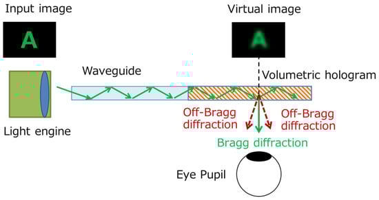
Figure 1.
HMD optical system with volume holographic waveguide and conceptual diagram of degraded image resolution by off-Bragg diffraction.
Figure 1 shows the conceptual diagram of the effect of the off-Bragg diffraction on the display-image quality. In volume holograms, diffracted light is generated even under conditions that do not entirely match Bragg conditions, and this diffraction is called off-Bragg diffraction [30,31,32]. Each readout light ray is propagated in the waveguide at a slightly different angle; therefore, the off-Bragg diffraction generated unintended, reproduced light from readout rays other than the Bragg-matching ray. Therefore, the off-Bragg diffraction may have reduced the visibility of the displayed contents, such as characters and figures. It is essential to analyze and evaluate these effects and clarify the requirements for developing practical volume holographic waveguides.
To accurately evaluate the display performance, the off-Bragg diffraction process in the waveguide was formulated and incorporated into the previous analytical model of the observed virtual image for the volume holographic waveguide.
The analytical model is described below (see Figure 2), with a specific, single pixel as an example. The ray angle for the single pixel was uniquely determined by the pixel’s position and the focal length of the lens. Once the eye’s pupil position was selected, the output position of the reproduced light from the waveguide surface was also determined. The reproduced light contained the Bragg and off-Bragg diffraction lights, and the sum of these lights determined the observed light intensity for the single pixel.
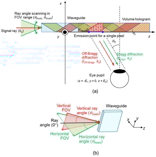
Figure 2.
(a) Schematic of analytical model of the waveguide with off-Bragg diffraction; (b) Geometric definition of ray angles of readout light (θHcalc and θVcalc).
The Bragg diffraction intensity from the volume hologram depended on the volume of the illuminated hologram areas. When the Bragg condition was satisfied, the diffraction intensity was proportional to the square of the volume of the illuminated hologram area based on the first-born approximation [33,34,35]. Conversely, the off-Bragg diffraction intensity depended on the off-Bragg vector (δKg) and the volume of the illuminated holographic areas [30,31]. Thus, the diffraction light intensity, (Idiff) including the Bragg and off-Bragg diffractions, is given by
where r is the position vector, Δn is the holographic strength, Ein is the amplitude of the electric field of the readout light, and V is the illuminated volume of the hologram, which is determined by the position and size of the eye’s pupil and the diffraction light’s direction [29]. Notably, if the illuminated volume hologram is split into several areas, each diffracted electrical field should be summed up to account for the phase differences, as in the reported model [29]. The off-Bragg vector, δKg, is defined by
where Kg is the grating vector, and ks, kr, kp, and kd are the wave vectors inside the waveguide for the signal, reference, readout, and diffracted (reproduced) light, respectively. For the Bragg-matching condition, kd = ks, and kp = kr; thus, δKg becomes zero. Considering the coordinate axis (Figure 2), the wave vector of the readout light, kp, is expressed as
where λ is the wavelength of the signal light, θVcalc and θHcalc are the vertical and horizontal ray angles of the input image outside the waveguide, respectively, and ngl is the refractive index of the waveguide.
In our volume holographic waveguide, we assumed that many gratings were recorded so that all of the readout light rays in the waveguide could be diffracted as if they were reflected by a single mirror tilted at 45°. For example, the signal light propagating along the z-axis was diffracted to the −x direction. In this case, the wave vector, kd, of the diffracted light is given by
where θV and θH are the vertical and horizontal ray angles outside the waveguide, respectively. They also represent the viewing angles of the observed virtual image.
The grating vectors lie on the xz-surface and are inclined at 45° with respect to the x-axis. Thus, the grating vector, Kg, is written as
Using the aforementioned wave vector expressions, δKg is transformed as follows:
Finally, the light intensity at the specific, single pixel in the observed virtual image is calculated as follows:
For simplicity, we assumed that the gratings required to display the entire virtual image were equally recorded, and that their hologram strength, Δn, was independent of the ray angle and position vector r. In our calculation, the eye relief, Er (the distance from the output surface of the waveguide to the eye’s pupil along the x-axis), was set to 22 mm, and the eye position, Ep (the distance from the input edge surface of the waveguide to the eye’s pupil along the z-axis), was 25 mm. The diameter of the eye’s pupil generally varied according to the brightness of the surrounding environment [36]. An intermediate size of 3 mm was used. The light-source wavelength was assumed to be a single wavelength of 555 nm. The refractive index of the waveguide was 2.3, characteristic of an ideal photorefractive material.
3. Results and Discussions
The display-resolution performance of the virtual image was investigated using the concept of the point-spread function. A point image, in which only one specific pixel was turned on, was input on the edge surface of the waveguide. Thereafter, the spread of the output virtual image was evaluated in terms of the full-width at half-maximum (FWHM) viewing angle. First, we evaluated it by varying the waveguide thickness, t, from 0.3 to 4.0 mm, while maintaining the ray angle of the point image at 0.1°. Figure 3 shows the calculation results for the ordinary volume holographic waveguide without using the line-symmetric image-input method. The result indicated that the FWHM angle width was virtually inversely proportional to t because the thicker the waveguide, the higher the angular selectivity of the Bragg diffraction, and the more the off-Bragg diffraction will be suppressed. Therefore, the display resolution can be improved by increasing the waveguide thickness although this will increase the device’s weight.
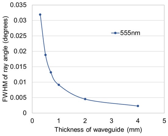
Figure 3.
Calculation results of display resolution by conventional volume holographic waveguide with one-sided image input.
Next, the ray-angle dependence of the display-resolution performance was investigated. The calculation results are shown in Figure 4. In this calculation, t was set at 1 mm. The spread of the point image varied periodically as a function of the ray angle, and fatal resolution-deterioration ray angles were observed. The International Council of Ophthalmology defines a visual acuity of 0.8 or higher as characteristic of normal vision [37]. We defined a criterion for the required resolution performance of the waveguide as an FWHM angle width of less than 0.02°, corresponding to a visual acuity of 0.8. At a ray angle of 4.6°, which was the worst resolution ray angle in our calculation, the FWHM was 0.13°. Therefore, a waveguide thickness of 1 mm was found to be insufficient for the ordinary volume holographic waveguide. Although the resolution performance can be improved by increasing the waveguide thickness, sufficient resolution cannot be achieved with a realistic thickness.
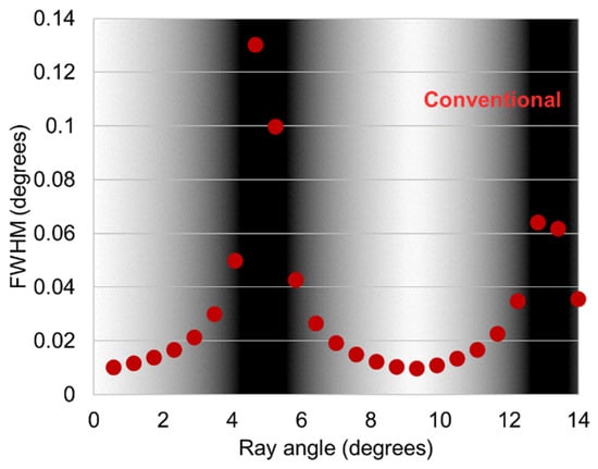
Figure 4.
Calculation results of ray-angle dependence of display resolution (red circle dots) and luminance distribution according to each ray angle (background shading) with conventional one-sided image input.
A factor responsible for the periodic deterioration of the resolution performance is the variation in the interaction volume of the signal light during holographic diffraction, as previously clarified [29]. The angle selectivity of the Bragg diffraction depends on the volume of the illuminated hologram. Thus, the influence of the off-Bragg diffraction becomes more pronounced at viewing angles where the interaction volume decreases. In addition, the diffracted intensity is reduced even for the Bragg-matching ray angles in these small-interaction volume regions, indicating a close relationship between the luminance uniformity of the virtual image and the display-resolution performance.
The luminance distribution of the virtual image is shown in the background of Figure 4. Comparing the display resolution (FWHM) and luminance distributions showed that the display-resolution performance had remarkably deteriorated at the ray angle with low luminance. It indicated that, if the luminance distribution of the virtual image were improved using the previously proposed line-symmetric image-input method [29], the display resolution could be improved.
The following is a brief description of the line-symmetric image-input method, and Figure 5 depicts a schematic of our proposed method. In our previous report, the identified issue of the dark lines, which are generated on the virtual image due to the changes in the volume of the signal-light-illuminated volume hologram area, depends on the location on the waveguide [29]. Therefore, we focused on a pair of signal-light rays with a horizontal ray angle, +a° and −a°, and we observed that these signal-light rays propagated in the volume holographic waveguide with the same TIR period but with a half-cycle phase shift. This indicated that the two rays had a complemental relation to the interaction hologram volume. Therefore, if we input a line-symmetric image with a symmetry axis of a horizontal ray angle of 0°, another diffracted light from the line-symmetric point within the input image compensated for the variation in the diffracted light intensity.
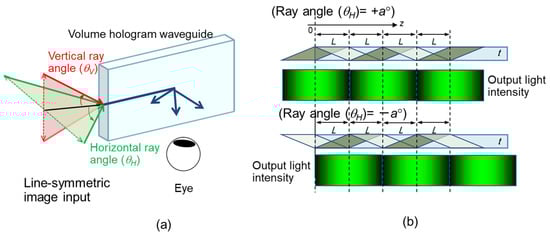
Figure 5.
Schematic of (a) line-symmetric image input; (b) light-propagation pass and output-light intensity at each position of the waveguide.
Similar to the improvement in the luminance uniformity, the display-resolution performance can be improved using the line-symmetric image-input method. Figure 6 shows the normalized intensity distribution in the virtual image for the input-point image, with and without the line-symmetric image-input method. In this calculation, t was 1 mm, and the input-point image was placed at the position corresponding to a ray angle of approximately 4.6°, which is the lowest-resolution ray angle (Figure 4). The FWHM angle width for the line-symmetric image-input method was reduced to 0.01°, which was a sufficient resolution for a person with a visual acuity of 0.8, whereas it was 0.13° in the conventional one-sided image input, as shown earlier. Therefore, the line-symmetric image-input method improved the display-resolution performance by a factor of 10.
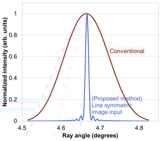
Figure 6.
Luminance distribution of point image with line-symmetric image input (blue line).
Figure 7 shows the ray-angle dependence of the display-resolution performance for the line-symmetric image-input method. The waveguide thickness, t, varied from 0.7 to 3.0 mm. For reference, the result for the conventional one-sided input method is shown again. The line-symmetric image-input method did not completely compensate for the variation in the interaction volume; therefore, even in the line-symmetric input method, the FWHM angle width slightly varied depending on the ray angle. The thicker the waveguide, the longer the TIR period [29]; thus, the cycle of change in the resolution also became longer in the thicker waveguide. When t = 0.7 mm, the FWHM angle width became larger than the resolution criterion of 0.02° in a periodic manner. However, for a waveguide thickness exceeding 1.0 mm, the display-resolution performance satisfied the criterion at all ray angles. Therefore, when the line-symmetric image-input method was employed, the volume holographic waveguide provided sufficient resolution across the entire FOV with a realistic thickness.
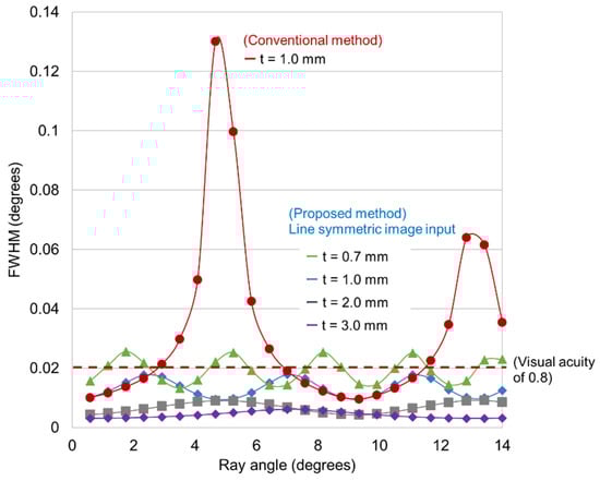
Figure 7.
Waveguide thickness and FOV-dependence of display resolution with line-symmetric image input.
4. Conclusions
We built a mathematical model of a volume holographic waveguide and analyzed the display resolution of the observed virtual image, considering the off-Bragg diffraction. The display-resolution performance was better in the thicker waveguide because the angular selectivity of the Bragg diffraction was higher in the thicker hologram. The performance periodically varied with the viewing angle of the virtual image because the interaction hologram volume periodically varied with the ray angle in the volume holographic waveguide. With the conventional one-sided input, the input-point image significantly spread at a particular ray angle, at which a rather low level of luminance was observed in the virtual image because of the small interaction volume during the holographic diffraction. At the lowest-resolution ray angle, the input-point image was broadened more than 0.1° for a 1-mm-thick waveguide. Therefore, a volume holographic waveguide with adequate resolution performance and realistic thickness cannot be realized using the conventional one-sided input method.
Contrarily, our previously proposed line-symmetric image-input method significantly improved the resolution performance. In this method, the input image was symmetrically arranged with respect to the horizontal ray angle of 0°, and another diffracted light from the line-symmetric point within the input image compensated for the variation in the diffracted-light intensity. We discovered that the spread of the point image was suppressed to 0.01°, which is a sufficient resolution for a person with a visual acuity of 0.8. Therefore, using the line-symmetric image-input method, the volume holographic waveguide provided sufficient resolution with a realistic thickness. Thus, we clarified that the line-symmetrical image-input method that compensates for the interaction region between the signal light and volume hologram is mandatory to achieve a practical display resolution and luminance uniformity for the volume holographic waveguide.
Author Contributions
Conceptualization, T.N. and R.F.; Methodology, T.N. and R.F.; Software, T.N.; Validation, T.N. and R.F.; Formal Analysis, T.N.; Investigation, T.N.; Writing—original draft preparation, T.N.; Writing—Review and Editing, T.N. and R.F.; Visualization, T.N.; Supervision, R.F. All authors have read and agreed to the published version of the manuscript.
Funding
This research received no external funding.
Institutional Review Board Statement
Not applicable.
Informed Consent Statement
Not applicable.
Data Availability Statement
Not applicable.
Conflicts of Interest
The authors declare no conflict of interest.
References
- Van Krevelen, D.W.F.; Poelman, R. A survey of augmented reality technologies, applications and limitations. Int. J. Virtual Real. 2010, 9, 1–20. [Google Scholar] [CrossRef]
- Sutherland, I.E. The ultimate display. Proc. IFIP 1965, 65, 506–508. [Google Scholar]
- Kress, B.C. Optical Architectures for Augmented-, Virtual-, and Mixed-Reality Headsets; SPIE Press: Bellingham, WA, USA, 2020. [Google Scholar]
- Popovich, M.; Sagan, S. Application specific integrated lenses for displays. In SID International Symposium Digest of Technical Papers; The Society for Information Display: Campbell, CA, USA, 2000; pp. 1060–1063. [Google Scholar]
- Levola, T. Diffractive optics for virtual reality displays. J. Soc. Inf. Disp. 2006, 14, 467–475. [Google Scholar] [CrossRef]
- Levola, T.; Laakkonen, P. Replicated slanted gratings with a high refractive index material for in and outcoupling of light. Opt. Express 2007, 15, 2067–2074. [Google Scholar] [CrossRef]
- Kress, B.C.; Cummings, W.J. Towards the ultimate mixed reality experience: HoloLens display architecture choices. In SID International Symposium Digest of Technical Papers; The Society for Information Display: Campbell, CA, USA, 2017; pp. 127–131. [Google Scholar]
- Grey, D.; Talukdar, S. Exit Pupil Expanding Diffractive Optical Waveguide Device. International Patent Application WO 020643, 11 February 2016. [Google Scholar]
- Nakamura, T.; Takashima, Y. Design of discretely depth-varying holographic grating for image guide based see-through and near-to-eye displays. Opt. Express 2018, 26, 26520–26533. [Google Scholar] [CrossRef]
- Li, Z.; Lin, P.; Huang, Y.W.; Park, J.S.; Chen, W.T.; Shi, Z.; Qiu, C.W.; Cheng, J.X.; Capasso, F. Meta-optics achieves RGB-achromatic focusing for virtual reality. Sci. Adv. 2021, 7, eabe4458. [Google Scholar] [CrossRef]
- Lee, G.Y.; Hong, J.Y.; Hwang, S.; Moon, S.; Kang, H.; Jeon, S.; Kim, H.; Jeong, J.H.; Lee, B. Metasurface eyepiece for augmented reality. Nat Commun. 2018, 9, 4562. [Google Scholar] [CrossRef]
- Zhou, Y.; Kravchenko, I.I.; Wang, H.; Zheng, H.; Gu, G.; Valentine, J. Multifunctional metaoptics based on bilayer metasurfaces. Light Sci. Appl. 2019, 8, 80. [Google Scholar] [CrossRef]
- Gabor, D. A new microscopic principle. Nature 1948, 161, 777–778. [Google Scholar] [CrossRef]
- Kogelnik, H. Coupled wave theory for thick hologram gratings. Bell Syst. Tech. J. 1969, 48, 2909–2947. [Google Scholar] [CrossRef]
- Van Heerden, P.J. Theory of optical information storage in solids. Appl. Opt. 1963, 2, 393–400. [Google Scholar] [CrossRef]
- Külich, H.C. A new approach to read volume holograms at different wavelengths. Opt. Commun. 1987, 64, 407–411. [Google Scholar] [CrossRef]
- Ashkin, A.; Boyd, G.D.; Dziedzic, J.M.; Smith, R.G.; Ballman, A.A.; Levinstein, J.J.; Nassau, K. Optically-induced refractive index inhomogeneities in LiNbO3 and LiTaO3. Appl. Phys. Lett. 1966, 9, 72–74. [Google Scholar] [CrossRef]
- Fujimura, R.; Shimura, T.; Kuroda, K. Multiplexing capability in polychromatic reconstruction with selective detection method. Opt. Express 2010, 18, 1091–1098. [Google Scholar] [CrossRef]
- Wakunami, K.; Hsieh, P.Y.; Oi, R.; Senoh, T.; Sasaki, H.; Ichihashi, Y.; Okui, M.; Huang, Y.P.; Yamamoto, K. Projection-type see-through holographic three-dimensional display. Nat. Commun. 2016, 7, 12954. [Google Scholar] [CrossRef]
- Mukawa, H.; Akutsu, K.; Matsumura, I.; Nakano, S.; Yoshida, T.; Kuwahara, M.; Aiki, K. A full-color eyewear display using planar waveguides with reflection volume holograms. J. Soc. Inf. Disp. 2009, 17, 185–193. [Google Scholar] [CrossRef]
- Kasai, I.; Tanijiri, Y.; Endo, T.; Ueda, H. A practical see-through head mounted display using a holographic optical element. Opt. Rev. 2001, 8, 241–244. [Google Scholar] [CrossRef]
- Ayres, M.R.; Anderson, K.; Urness, A.; Schlottau, F. Skew Mirrors, Methods of Use, and Methods of Manufacture. U.S. Patent 10,180,520, 15 January 2019. [Google Scholar]
- Han, J.; Liu, J.; Yao, X.; Wang, Y. Portable waveguide display system with a large field of view by integrating freeform elements and volume holograms. Opt. Express 2015, 23, 3534–3549. [Google Scholar] [CrossRef]
- Draper, C.T.; Bigler, C.M.; Mann, M.S.; Sarma, K.; Blanche, P.A. Holographic waveguide head-up display with 2-D pupil expansion and longitudinal image magnification. Appl. Opt. 2019, 58, A251–A257. [Google Scholar] [CrossRef]
- Utsugi, T.; Sasaki, M.; Ono, K.; Tada, Y. Volume holographic waveguide using multiplex recording for head-mounted display. ITE Transact. Media Tech. Appl. 2020, 8, 238–244. [Google Scholar] [CrossRef]
- Shen, Z.; Zhang, Y.; Liu, A.; Weng, Y.; Li, X. Volume holographic waveguide display with large field of view using a Au-NPs dispersed acrylate-based photopolymer. Opt. Mater. Express 2020, 10, 312–322. [Google Scholar] [CrossRef]
- Xiao, J.; Liu, J.; Lv, Z.; Shi, X.; Han, J. On-axis near-eye display system based on directional scattering holographic waveguide and curved goggle. Opt. Express 2019, 27, 1683–1692. [Google Scholar] [CrossRef] [PubMed]
- Wu, Y.; Chen, C.P.; Zhou, L.; Li, Y.; Yu, B.; Jin, H. Design of see-through near-eye display for presbyopia. Opt. Express 2017, 25, 8937–8949. [Google Scholar] [CrossRef] [PubMed]
- Nakamura, T.; Fujimura, R. Field of view enlargement with line symmetric image input technique of volumetric hologram waveguide for head mounted displays. Opt. Rev. 2021, 28, 693–703. [Google Scholar] [CrossRef]
- Coufal, H.J.; Psaltis, D.; Sincerbox, G.T. Holographic Date Storage; Springer: Berlin/Heidelberg, Germany, 2000. [Google Scholar]
- Fujimura, R.; Shimura, T.; Kuroda, T. Theory of Polychromatic Reconstruction for Volume Holographic Memory, Holograms—Recording Materials and Applications; IntechOpen: London, UK, 2011. [Google Scholar]
- Solymar, L.; Webb, D.J.; Grunnrt-Jepsen, A. The Physics and Applications of Photorefractive Materials; Clarendon Press Oxford: Oxford, UK, 1996. [Google Scholar]
- Born, M.; Wolf, E. Principle of Optics: 60th Anniversary Edition; Cambridge University Press: Cambridge, UK, 2019. [Google Scholar]
- Harthong, J.; Medjahed, A. Thickness measurement for volume holograms by analysis of first-order diffraction. Appl. Opt. 1992, 31, 1803–1809. [Google Scholar] [CrossRef]
- Gombkoto, B.; Koppa, P.; Suto, A.; Lorincz, E. Computer simulation of reflective volume gratings holographic data storage. J. Opt. Soc. Am. A 2007, 24, 2075–2081. [Google Scholar] [CrossRef]
- Andrew, B.; Watson, A.B.; Yellott, J.I. A unified formula for light-adapted pupil size. J. Vis. 2012, 12, 12. [Google Scholar]
- International Council of Ophthalmology. Visual Acuity Measurement Standard. 1984. Ital. J. Ophthalmol. 1988, II/I, 1–15. [Google Scholar]
Publisher’s Note: MDPI stays neutral with regard to jurisdictional claims in published maps and institutional affiliations. |
© 2022 by the authors. Licensee MDPI, Basel, Switzerland. This article is an open access article distributed under the terms and conditions of the Creative Commons Attribution (CC BY) license (https://creativecommons.org/licenses/by/4.0/).