Article

The Investigation of Underwater Wireless Optical Communication Links Using the Total Reflection at the Air-Water Interface in the Presence of Waves

1
Department of Electrical and Computer Engineering, Southern University of Science and Technology, Shenzhen 518055, China
2
Sino-German College of Intelligent Manufacturing, Shenzhen Technology University, Shenzhen 518118, China
*
Author to whom correspondence should be addressed.
These authors contributed equally to this work.
Photonics 2022, 9(8), 525; https://doi.org/10.3390/photonics9080525
Submission received: 30 January 2022 / Revised: 18 July 2022 / Accepted: 19 July 2022 / Published: 28 July 2022
(This article belongs to the Special Issue Next-Generation Optical Wireless Communication (OWC))

Abstract

:
With the development of underwater exploration, underwater networking is in urgent demand. At present, underwater wireless optical communication (UWOC) is primarily based on line-of-sight (LOS) communication links. However, the underwater environment is so complicated that LOS communication links are easily affected by a couple of factors such as air bubbles, turbidity, oceanic turbulence, and so on. We put forward novel UWOC links using the total reflection at the air-water interface, which can mitigate those phenomena. This paper aims to investigate a UWOC link based on the total reflection at the air-water interface. In our work, we achieved the maximum data rate of 300 Mb/s and a bit error rate (BER) of 3.10 × 10⁻³ under the forward error correction (FEC) with the total reflection angle of 7°. Furthermore, we verified the performance of the total reflection-based UWOC links at the air-water interface in the presence of waves and evaluated the impact on the UWOC links when the frequency and amplitude of the waves varied.

1. Introduction

Recently, underwater wireless optical communication (UWOC) has attracted the attention of researchers due to its large bandwidth, high data rates, and lack of electromagnetic interference [1,2]. Traditionally, underwater acoustic communication (UAC) and radio frequency (RF) communication are the two main methods of underwater wireless communication (UWC). Although UAC has the overwhelming advantage of long-distance transmission [3], it is hard to achieve high-speed communication because of the narrow bandwidth of the acoustic wave. Compared to UAC, RF communication can offer a larger bandwidth and a higher data rate. However, RF communication is limited to short-distance transmissions because of the high conductivity of seawater to radio frequencies [4,5].
As novel underwater wireless communication technologies, UWOC can balance long-distance transmission and high data rates [6,7,8,9,10,11]. When targeting long-distance UWOC, it is possible to exploit the low-attenuation window in the electromagnetic spectrum, which locates in the visible spectrum the approximate peak wavelength of 522 nm, as shown in Figure 1. With the expansion of Internet-of-Things (IoT) technology, the ocean will be explored deeply by humans. Ocean buoys, satellites, aircraft, vessels, and vehicles have formed the satellite-terrestrial network, which will cover the ocean using the UWOC network in the near future [12].
Despite UWOC having significant achievements, the complexity of the underwater environment still raises challenges for UWOC. There are a couple of unforeseen factors such as fish schools, seabed rocks, turbidity, and oceanic turbulence [13,14,15,16]. These greatly degrade the performance of the UWOC links, which primarily utilize line-of-sight (LOS) communication [17,18,19,20]. For example, seabed rocks block the communication link so that the UWOC transmission is interrupted, as shown in Figure 2. To keep UWOC links reliable and robust, many researchers have made some progress in non-line-of-sight (NLOS) UWOC [21,22,23,24,25,26,27]. Sun et al. experimentally demonstrated a UWOC system at a data rate of 85 Mb/s within a transmission distance of 30 cm in emulated highly turbid harbor water by using an NLOS link [28]. Noha Anous et al. evaluated the proposed models of LOS and NLOS vertical underwater transmission links [20]. Tang et al. discussed the path loss of NLOS on UWOC links [29]. Liu et al. proposed an NLOS-scattering-channel model for the UWOC system [30]. In this paper, we demonstrated a novel NLOS UWOC link using the total internal reflection at the air-water interface and further investigated the impact on the UWOC links when the frequency and amplitude of the waves varied.

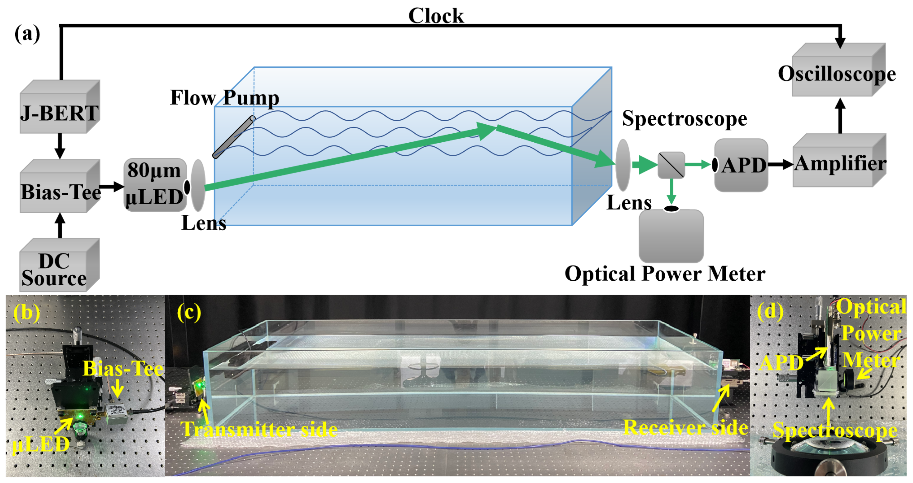
2. Materials and Methods

InGaN green micro-LEDs with a size of 80 μm × 80 μm were fabricated from commercial III-nitride LED wafers grown on a c-plane sapphire substrate by metalorganic chemical vapor deposition (Xiamen Changelight Co., Ltd., Xiamen, China). The LED had a typical p-i-n structure with an u-GaN buffer layer, n-GaN layer, InGaN/GaN multiple quantum wells (MQWs), and a p-GaN layer. Photolithography and inductively coupled plasma (ICP) etching, with SiO2 as a hard mask, were performed to define the mesa structure [31]. Then, current spreading layer (CSL) was deposited with a 100 nm indium-tin-oxide (ITO) layer by sputter. In order to achieve ohmic contact between CSL and p-GaN, rapid thermal processing (RTP) was used in an atmosphere of nitrogen and oxygen. A Ti (20 nm)/Al (100 nm)/Ti (20 nm)/Au (50 nm) stack layer was evaporated onto the CSL and n-GaN as the p-electrodes and n-electrodes by E-Beam Evaporator. The pictures of the 80 μm × 80 μm InGaN-based micro-LED are shown in Figure 3.
Figure 4 demonstrates the UWOC system using an InGaN-based micro-LED light source and non-return-to-zero on-off keying (NRZ-OOK) modulation. At the transmitter end, the micro-LED was driven by a bias tee (mini-circuits ZFBT-6GW+) that combines a direct current (DC) from KEYSIGHT B2902A with pseudo-random binary sequences (PRBS) from Agilent J-BERT E8403A. The emission light was collimated by a plano-concave lens and then transmitted through a water tank of dimensions 1.8 m × 0.5 m × 0.3 m. In the water tank, we achieved the communication links by utilizing the total internal reflection at the air-water interface. At the receiver end, the optical output signal was focused by a Convex lens and then captured by a 100 MHz bandwidth photodetector (Hamamatsu C12702-11). The distance between the light source to the lens, the lens to tank entrance, tank length, tank end to collection lens, and collection lens to the detector were 1 cm, 10 cm, 180 cm, 10 cm, and 4 cm, respectively. The electrical output signal of the detector was amplified by the power amplifier (mini-circuits ZHL-6A-S+) and then tested by Agilent E8403A error detector to obtain BER. In this proposed UWOC system, a wave generator (SCP-150M) was used to achieve waves. Its power consumption is 50 W at maximum. It can make square waves or sine waves by changing the frequency and the magnitude.

3. Results and Discussion

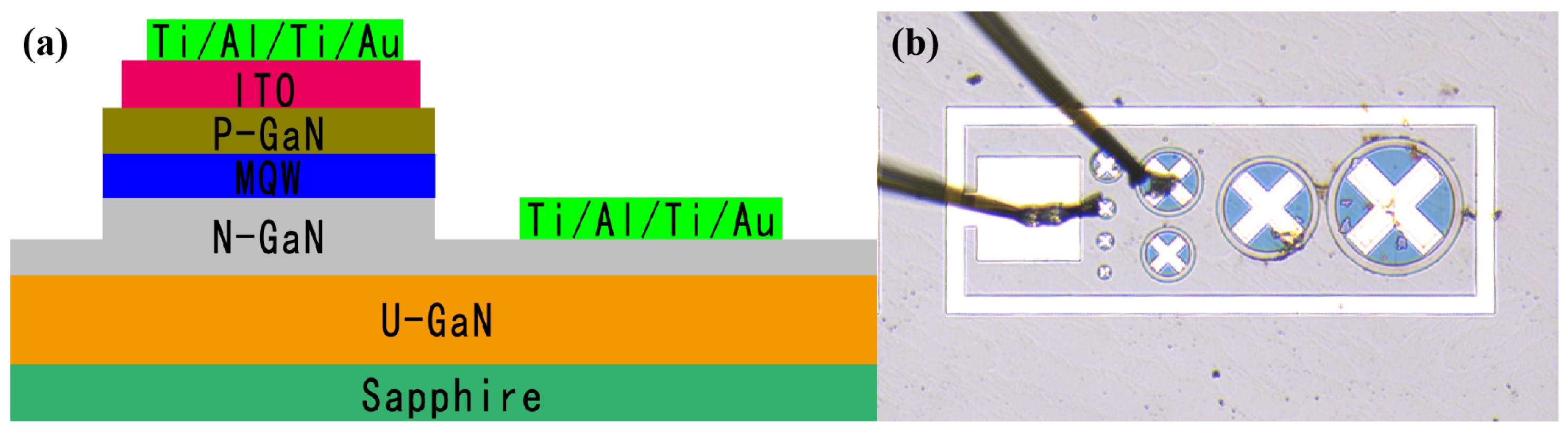
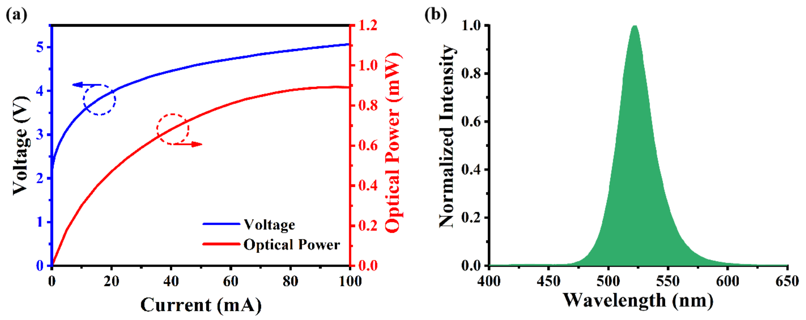
3.1. Characteristic of InGaN-Based Micro-LED

The results of the light-output power versus current (LI) and current versus voltage (IV) test of InGaN-based Micro-LED are shown in Figure 5a. It can be observed that the threshold voltage of the micro-LED is about 2.4 V, and as the voltage increases, the LI curve gradually becomes linear. When a small AC modulated signal is added, the optical power will change linearly; therefore, micro-LED modulation performance is very suitable for UWOC systems [32,33].
The electroluminescence (EL) spectra in Figure 5b were measured using a JETI Spectraval 1501 Spectrometer. The experimental results show the InGaN-based mcro-LED peak wavelength at 80 mA is around 522 nm with a full-width at half-maximum (FWHM) of 33 nm.
Figure 6a presents the performance of the InGaN-based micro-LED frequency response and summarizes the characteristic of −3 dB modulation bandwidth at different injection currents from 10mA to 100 mA [34,35]. The dashed line indicates the −3 dB bandwidth level. Figure 6b shows that with the injection current increasing from 10 mA to 100 mA; the −3 dB bandwidth is also increasing from 26.3 MHz to 98.1 MHz. Note that the APD photodetector used for the frequency response test only has a bandwidth of 100 MHz, which limits the maximum measured −3 dB modulation bandwidth of the InGaN-based micro-LED. In consideration of the working life of the InGaN-based micro-LED, we chose 80 mA, which corresponds to a voltage of 5.1 V combined with the alternating voltage of 1.4 V for the operation point of the UWOC system.
Moreover, we put forward a UWOC system using InGaN micro-LED arrays, including 5000 pixels packaged by flip-chip technology. The pitch size of the micro-LED is 15 μm by 15 μm. The InGaN micro-LED arrays in parallel have an optical power of up to 3.5 mW at a 300 mA drive current. The system achieved a high data rate of 92 Mb/s with a BER of 3.41 × 10⁻³ and was estimated to reach 50 m in tap water and 10 m in seawater. Thus, we balanced the high bandwidth and the optical power in UWOC links.

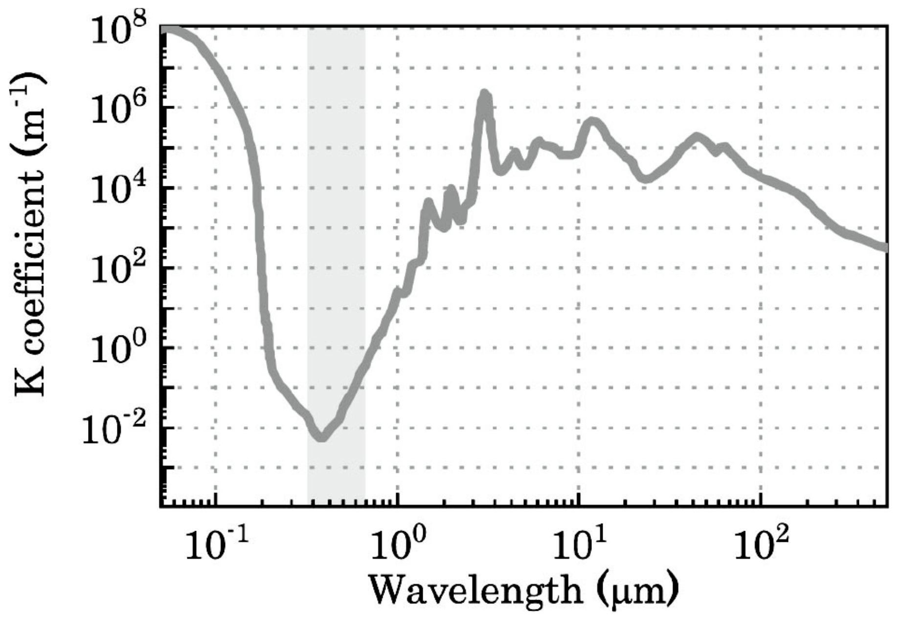
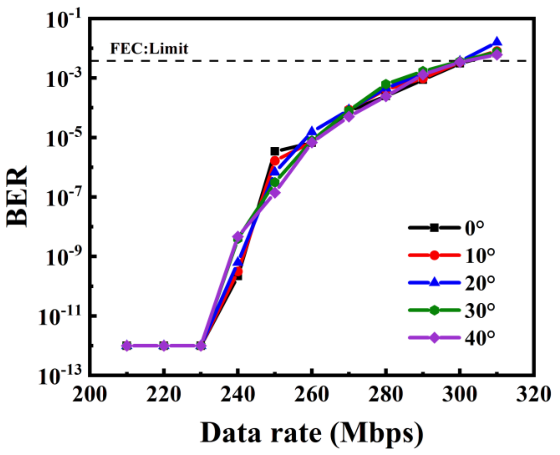
3.2. Selection of Total Reflection Angle

To select a suitable total reflection angle, we firstly conducted a total-reflection-angle test experiment. A tilt was used to achieve total reflection. By adjusting the distance between the transmitter and the receiver, and using the long or short sides of the water tank, we achieved a UWOC link based on a random total internal reflection angle. In this experiment, 0° to 40° were chosen for the total-reflection experiment test; the experimental results are shown in Figure 7.
Figure 7 shows that total reflection angles of 0° to 40° has little effect on the experimental results. Therefore, any total reflection angle from 0° to 40° will have a similar effect on the performance of the UWOC system. We selected a UWOC link with a total reflection angle of 7° for the following frequency and amplitude experiments. In order to compare the results with the subsequent experiments under non-ideal conditions, the optical power curve and waveform under ideal 7° experimental conditions were tested. The experimental results are shown in Figure 8, we obtained the optical power as 80 μW, the amplitude of the waveform diagram is between −0.4 V and 0.4 V.

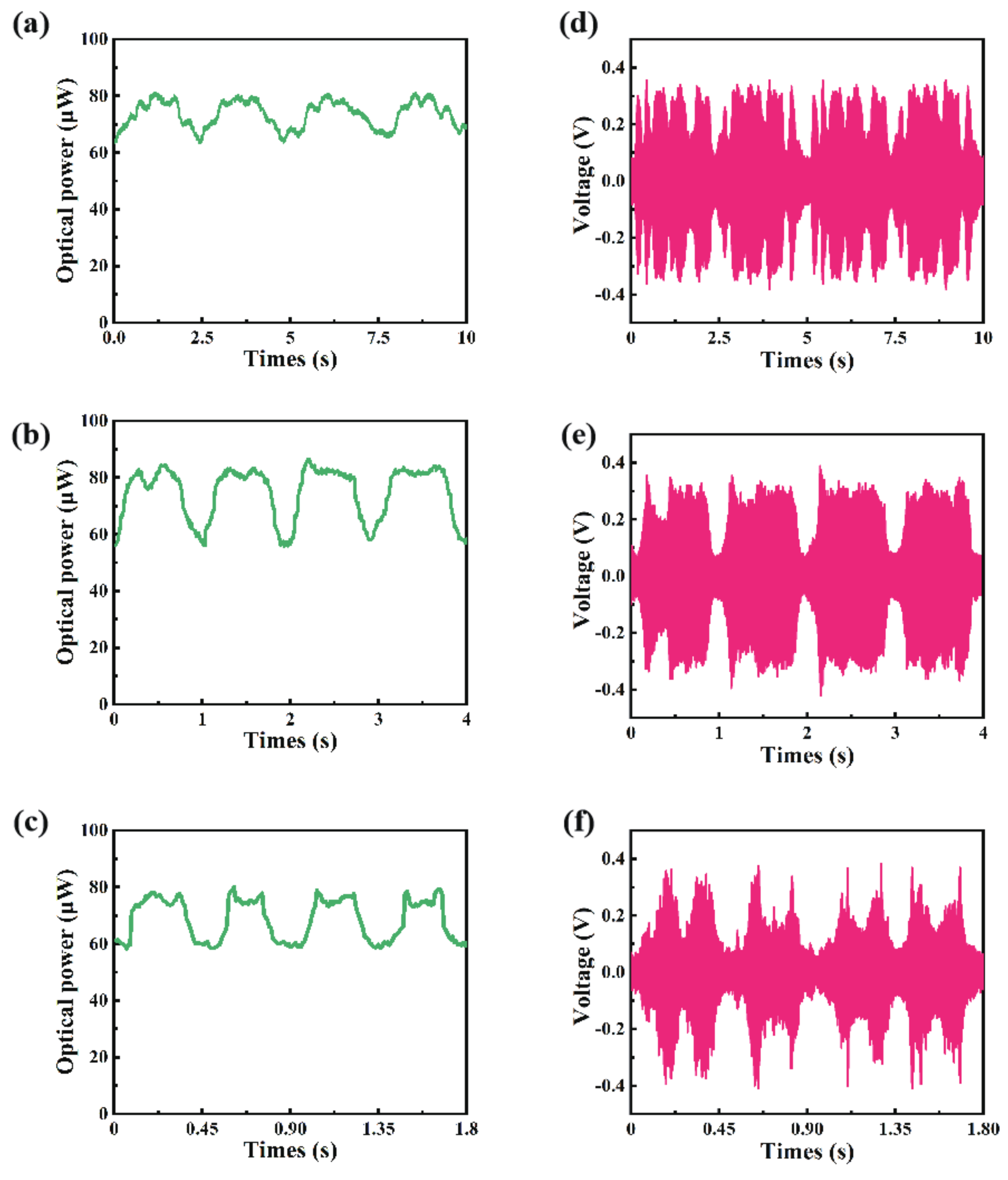
3.3. Research on Wave Frequencies

To investigate the impact of wave frequency on the UWOC link, waves of different frequencies were obtained by adjusting the flow pump power. Since the power of the flow pump is not continuously adjustable, we finally obtained three different frequencies, 0.4 Hz, 1 Hz, and 2.2 Hz. Based on these three different frequency conditions, the performance of the UWOC link with a total reflection angle of 7° was experimentally proved; Figure 9 shows the test results.
The corresponding optical power curves at three wave frequencies are illustrated in Figure 9a–c, and the amplitude variation ub the optical power at this experimental condition is 20 μW. Due to the periodic fluctuations of waves, the optical power curve also shows periodic changes, and the value of the optical power directly affects the photoelectric conversion of the photodetector. Figure 9d–f shows the waveform diagram with a data rate of 240 Mb/s at frequencies of 0.4 Hz, 1 Hz, 2.2 Hz, respectively. Note that the change in the waveform is very similar to the change in the optical power curve.
Figure 10 presents the relationship between data rates and BER under experimental conditions where the frequencies of optical power are different. Note that, in this part of the experiment, we controlled the optical power amplitude; only the frequency of the optical power was different. In Figure 10, we can clearly see that, although the frequency of optical power has changed, the relationship between data rate and BER is basically the same. Compared to Figure 7, the maximum data rate in the case of water surface fluctuations is only about 230 Mb/s, which is lower than 300 Mb/s when the water surface is stationary. Therefore, we draw a conclusion that the frequency variation of the optical power has an impact on the performance of the UWOC link, but the influence of different frequency variations on the UWOC link seems similar.

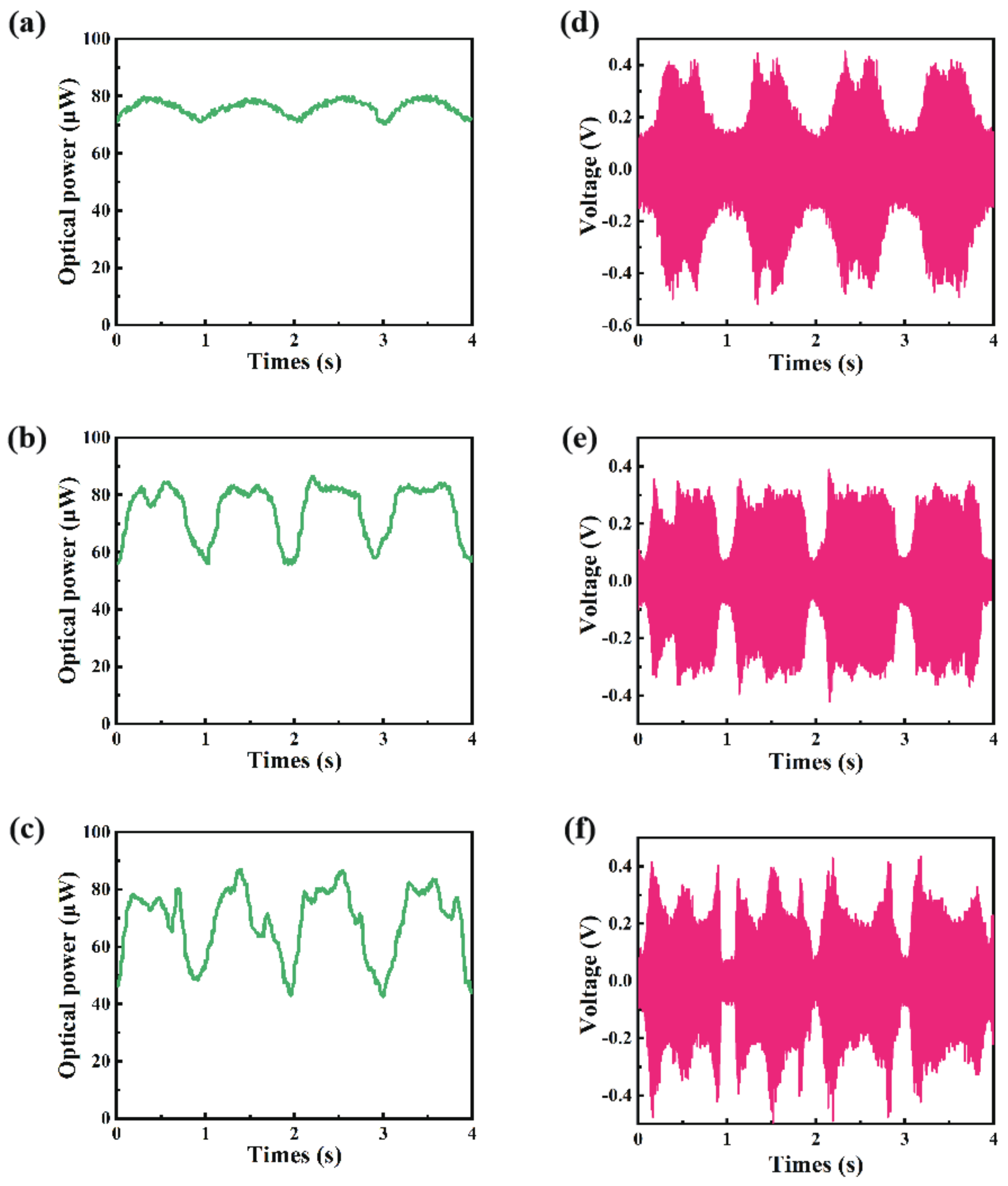
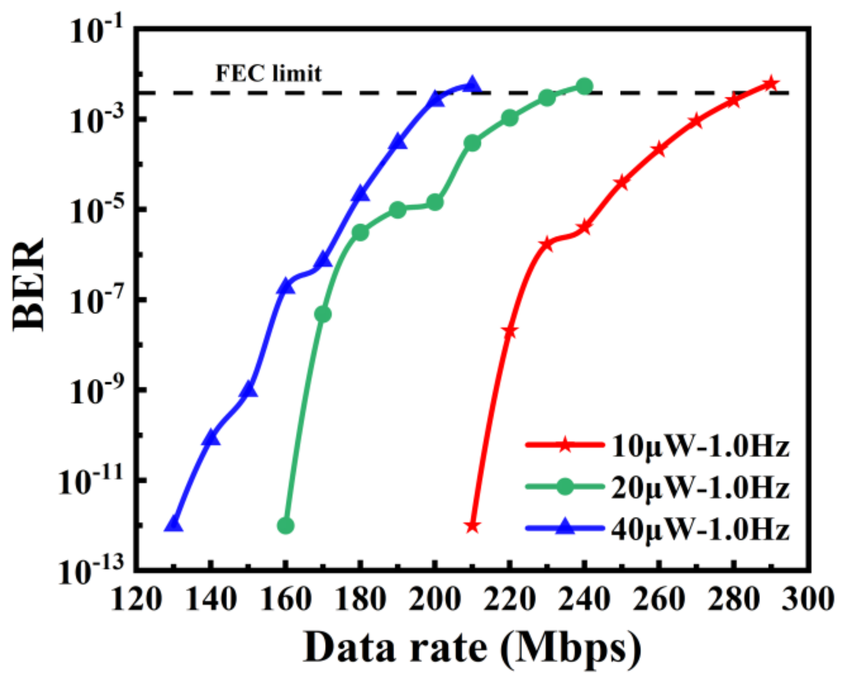
3.4. Research on Wave Amplitudes

Since different optical power fluctuation frequencies have little effect on the UWOC link, we further studied the influence of the optical power amplitude on the UWOC link. Over time, the waves will become increasingly smaller fluctuations, but the frequency variation of the waves is basically the same. Damped vibration can be used to explain this phenomenon. We finally observed three optical power variation amplitudes, 10 μW, 20 μW, and 40 μW. Based on these three different optical power variation amplitudes, we verified the performance of the UWOC link with a total reflection angle of 7°. The experimental results are shown in Figure 11.
Figure 11a–c shows the optical power variation curve with the optical power frequency of 1 Hz and the amplitude variation of 10 μW, 20 μW, and 40 μW, respectively. Figure 11d–f is their corresponding waveform diagram, respectively. Note that the data rate in Figure 11d is 290 Mb/s, the data rate in Figure 11e is 240 Mb/s, and the data rate in Figure 11f is 210 Mb/s.
Figure 12 shows the relationship between the data rate and BER under experimental conditions where the optical power vibration is at the same frequency but the optical power amplitude vibration is different. Due to the different magnitudes of the optical power amplitude, the maximum data rate that the UWOC link with a total reflection angle of 7° can reach under different experimental conditions of amplitude vibration is also different. Under the experimental condition where the optical power frequency is 1 Hz, the maximum achievable data rates of up to 280 Mb/s, 230 Mb/s, and 200 Mb/s were obtained at the optical power amplitudes variation of 10 μW, 20 μW, and 40 μW with the corresponding BERs of 2.63 × 10⁻³, 3.42 × 10⁻³, and 2.57 × 10⁻³, respectively.

4. Conclusions

In summary, we employed a single InGaN-based micro-LED with an 80 μm diameter and a 522 nm peak emission wavelength to build a UWOC link based on the total reflection at the air-water interface. It offered an alternative way to transmit data when the LOS UWOC link was interrupted. With the total reflection angle, a maximum data rate of 300 Mb/s UWOC link was achieved at a BER of 3.10 × 10⁻³. A flow pump was applied to simulate waves to create frequency and amplitude variation at the air-water interface. The experimental results showed that the highly controlled water with its waves can result in limited data rates of 200 Mb/s and a BER of 2.57 × 10⁻³. For data-rate performance, an NLOS optical link approach for seawater conditions is very challenging and will require a future detailed investigation. Since the modulation mode in this experiment was NRZ-OOK, the amplitude would affect the SNR and the BER of UWOC links easily. Furthermore, we will bring in the PPM modulation mode to improve the communication performance of our UWOC system, which is insensitive to amplitude variation.

Author Contributions

Conceptualization, Z.L. (Zhijian Lv) and G.H.; methodology, Z.L. (Zhijian Lv); software, H.Y.; validation, G.H., R.C. and Y.L.; formal analysis, H.Y.; investigation, G.H.; resources, G.H.; data curation, G.H.; writing-original draft preparation, G.H.; writing-review and editing, Z.L. (Zhijian Lv); visualization, G.H.; supervision, W.Z.; project administration, C.Q.; funding acquisition, Z.L. (Zhaojun Liu). All authors have read and agreed to the published version of the manuscript.

Funding

This work was supported by Special Funds for the Cultivation of Guangdong College Students’ Scientific and Technological Innovation (“Climbing Program” Special Funds, Project No. pdjh2020b0521), Key-Area Research and Development Program of GuangDong Province (Grant No. 2019B010925001), Shenzhen Overseas High-level Talent Innovation Team (Project Name: Micro-LED Displays Technology and Demonstration Innovation Team for Novel VR/AR Applications, Grant No. KQTD201708101103-13773), Guangdong Science and Technology funding (Project Name: High Speed Visible Light Communications based on RGB Micro-LED Arrays, Grant No. 2017B010114002), and Natural Science Foundation of Top Talent of SZTU (Grant No. GDRC202108).

Institutional Review Board Statement

Not applicable.

Informed Consent Statement

Not applicable.

Data Availability Statement

Not applicable.

Acknowledgments

The authors wish to thank Hao-Chung Kuo, Ke Zhang, and Lijiang Huang for their valuable suggestions and supports. Thanks also to Chiao Tung University, Hong Kong University of Science and Technology, and Shenzhen Sitan Technology Co., Ltd.

Conflicts of Interest

The authors declare no conflict of interest.

References

  1. Wei, Z.; Mao, S.; Li, Z.; Pepe, A.; Zhang, L.; Liu, X.; Chen, Y.; Dong, Y.; Fu, H.Y. Propagation analysis and experiment of near-infrared VCSEL-based diffuse optical wireless communication. Appl. Opt. 2020, 59, 6094–6101. [Google Scholar] [CrossRef] [PubMed]
  2. Burchardt, H.; Serafimovski, N.; Tsonev, D.; Videv, S.; Haas, H. VLC: Beyond point-to-point communication. IEEE Commun. Mag. 2014, 52, 98–105. [Google Scholar] [CrossRef]
  3. Song, A.; Stojanovic, M.; Chitre, M. Editorial Underwater Acoustic Communications: Where We Stand and What Is Next? IEEE J. Ocean. Eng. 2019, 44, 1–6. [Google Scholar]
  4. Palmeiro, A.; Martin, M.; Crowther, I.; Rhodes, M. Underwater Radio Frequency Communication. In Proceedings of the OCEANS 2011 IEEE-Spain, Santander, Spain, 6 June 2011; pp. 1–8. [Google Scholar]
  5. Chaitanya, D.E.; Sridevi, C.V.; Rao, G.S.B. Path Loss Analysis of Underwater Communication Systems. In Proceedings of the IEEE Technology Students’ Symposium, Kharagpur, India, 14–16 January 2011; pp. 65–70. [Google Scholar]
  6. Oubei, H.M.; Shen, C.; Kammoun, A.; Zedini, E.; Park, K.; Sun, X.; Liu, G.; Kang, C.; Ng, T.K.; Alouini, M.; et al. Light Based Underwater Wireless Communications. Jpn. J. Appl. Phys. 2018, 57, 8. [Google Scholar] [CrossRef]
  7. Zeng, Z.; Fu, S.; Zhang, H.; Dong, Y.; Cheng, J. A Survey of Underwater Optical Wireless Communications. IEEE Commun. Surv. Tutor. 2017, 19, 204–238. [Google Scholar] [CrossRef]
  8. Frank, H.; Radic, S. High bandwidth underwater optical communication. Appl. Opt. 2008, 47, 277–283. [Google Scholar]
  9. Arnon, S. Underwater optical wireless communication network. Opt. Eng. 2010, 49, 015001. [Google Scholar] [CrossRef]
  10. Farr, N.; Bowen, A.; Ware, J.; Pontbriand, C.; Tivey, M. An integrated, underwater optical/acoustic communications system. In Proceedings of the OCEANS’10 IEEE SYDNEY, Sydney, Australia, 24–27 May 2010; pp. 1–6. [Google Scholar]
  11. Elibol, A.; Garcia, R.; Gracias, N. A new global alignment approach for underwater optical mapping. Ocean Eng. 2011, 38, 1207–1219. [Google Scholar] [CrossRef]
  12. Domingo, M.C. An Overview of the Internet of Underwater Things. J. Netw. Comput. Appl. 2012, 35, 1879–1890. [Google Scholar] [CrossRef]
  13. Jamali, M.V.; Mirani, A.; Parsay, A.; Abolhassani, B.; Nabavi, P.; Chizari, A.; Khorramshahi, P.; Abdollahramezani, S.; Salehi, J.A. Statistical Studies of Fading in Underwater Wireless Optical Channels in the Presence of Air Bubble, Temperature, and Salinity Random Variations. IEEE Trans. Commun. 2018, 66, 4706–4723. [Google Scholar] [CrossRef]
  14. Oubei, H.M.; ElAfandy, R.T.; Park, K.; Ng, T.K.; Alouini, M.; Ooi, B.S. Performance Evaluation of Underwater Wireless Optical Communications Links in the Presence of Different Air Bubble Populations. IEEE Photonics J. 2017, 9, 7903009. [Google Scholar] [CrossRef] [Green Version]
  15. Elamassie, M.; Uysal, M. Performance Characterization of Vertical Underwater VLC Links in the Presence of Turbulence. In Proceedings of the 11th IEEE/IET International Symposium on Communication Systems, Networks Digital Signal Processing (CSNDSP18), Budapest, Hungary, 18–20 July 2018; pp. 1–6. [Google Scholar]
  16. Yi, X.; Li, Z.; Liu, Z. Underwater Optical Communication Performance for Laser Beam Propagation through Weak Oceanic Turbulence. Appl. Opt. 2015, 54, 1273–1278. [Google Scholar] [CrossRef]
  17. He, G.; Lv, Z.; Qiu, C.; Liu, Z. Performance Evaluation of 520nm Laser Diode Underwater Wireless Optical Communication Systems in the Presence of Oceanic Turbulence. In Proceedings of the SID International Symposium Digest of Technical Papers, Wuhan, China, 11–14 October 2020; Volume 51, pp. 47–50. [Google Scholar]
  18. Lu, Z.; Tian, P.; Chen, H.; Izak, B.; Fu, H.; Huang, X.; Jossue, M.; Fan, Y.; Wang, H.; Liu, X.; et al. Active Tracking System for Visible Light Communication Using a GaN-based micro-LED and NRZ-OOK. Opt. Express 2017, 25, 17971–17981. [Google Scholar] [CrossRef] [PubMed]
  19. Lv, Z.; He, G.; Qiu, C.; Fan, Y.; Wang, H.; Liu, Z. CMOS monolithic photodetector with a built-in 2-dimensional light direction sensor for laser diode based underwater wireless optical communications. Opt. Express 2021, 29, 16197–16204. [Google Scholar] [CrossRef]
  20. Anous, N.; Abdallah, M.; Uysal, M.; Qaraqe, K. Performance Evaluation of LOS and NLOS Vertical Inhomogeneous Links in Underwater Visible Light Communications. IEEE Access 2018, 6, 22408–22420. [Google Scholar] [CrossRef]
  21. Kedar, D.; Arnon, S. Non-line-of-sight optical wireless sensor network operating in multiscattering channel. Appl. Opt. 2006, 45, 8454–8461. [Google Scholar] [CrossRef]
  22. Marraccini, P.J.; Riza, N.A. Smart multiple-mode indoor optical wireless design and multimode light source smart energy-efficient links. Ocean Eng. 2013, 52, 055001. [Google Scholar] [CrossRef]
  23. Yuan, R.; Ma, J. Review of ultraviolet non-line-of-sight communication. China Commun. 2016, 13, 63–75. [Google Scholar] [CrossRef]
  24. Zhang, X.; Cao, Z.; Li, J.; Ge, D.; Chen, Z.; Vellekoop, I.M.; Koonen, A.M.J. Wide-coverage beam-steered 40-Gbit/s non-line-of-sight optical wireless connectivity for Industry 4.0. J. Light. Technol. 2020, 38, 6801–6806. [Google Scholar] [CrossRef]
  25. Jagadeesh, V.K.; Choudhary, A.; Bui, F.M.; Muthuchidambaranathan, P. Characterization of Channel Impulse Responses for NLOS Underwater Wireless Optical Communications. In Proceedings of the 2014 Fourth International Conference on Advances in Computing and Communications, Delhi, India, 24–25 May 2014; pp. 77–79. [Google Scholar]
  26. Lu, Z.; Tian, P.; Fu, H.; Jossue, M.; Huang, X.; Chen, H.; Zhang, X.; Liu, X.; Liu, R.; Zheng, L.; et al. Experimental Demonstration of Non-line-of-sight Visible Light Communication with Different Reflecting Materials Using a GaN-based micro-LED and Modified IEEE 802.11ac. AIP Adv. 2018, 8, 105017. [Google Scholar] [CrossRef] [Green Version]
  27. Sun, X.; Cai, W.; Alkhazragi, O.; Ooi, E.; He, H.; Chaaban, A.; Shen, C.; Oubei, H.M.; Khan, M.Z.M.; Ng, T.K.; et al. 375-nm Ultraviolet-laser Based Non-line-of-sight Underwater Optical Communication. Opt. Express 2018, 26, 12870–12877. [Google Scholar] [CrossRef]
  28. Sun, X.; Kong, M.; Alkhazragi, O.; Shen, C.; Ooi, E.; Zhang, X.; Buttner, U.; Ng, T.K.; Ooi, B.S. Non-line-of-sight Methodology for High-speed Wireless Optical Communication in Highly Turbid Water. Opt. Commun. 2020, 461, 125264. [Google Scholar] [CrossRef]
  29. Tang, S.; Dong, Y.; Zhang, X. On Path Loss of NLOS Underwater Wireless Optical Communication Links. In Proceedings of the 2013 MTS/IEEE OCEANS, Bergen, Norway, 10–14 June 2013; pp. 1–3. [Google Scholar]
  30. Liu, W.; Zou, D.; Xu, Z.; Yu, J. Non-line-of-sight scattering channel modeling for underwater optical wireless communication. In Proceedings of the IEEE International Conference on Cyber Technology in Automation, Shenyang, China, 8–12 June 2015; pp. 1265–1268. [Google Scholar]
  31. Liu, Z.; Lin, C.; Hyun, B.; Sher, C.; Lv, Z.; Luo, B.; Jiang, F.; Wu, T.; Ho, C.; Kuo, H.; et al. Micro-light-emitting diodes with quantum dots in display technology. Light-Sci. Appl. 2020, 9, 83. [Google Scholar] [CrossRef]
  32. Arvanitakis, G.N.; Bian, R.; McKendry, J.J.D.; Cheng, C.; Xie, E.; He, X.; Yang, G.; Islim, M.S.; Purwita, A.A.; Gu, E.; et al. Gb/s Underwater Wireless Optical Communications Using Series-Connected GaN micro-LED Arrays. IEEE Photonics J. 2020, 12, 1–10. [Google Scholar] [CrossRef]
  33. Liu, X.; Tian, P.; Wei, Z.; Yi, S.; Huang, Y.; Zhou, X.; Qiu, Z.; Hu, L.; Fang, Z.; Cong, C.; et al. Gbps Long-Distance Real-Time Visible Light Communications Using a High-Bandwidth GaN-Based micro-LED. IEEE Photonics J. 2017, 9, 7204909. [Google Scholar] [CrossRef]
  34. Fu, H.; Lu, Z.; Zhao, Y. Analysis of Low Efficiency Droop of Semipolar InGaN Quantum Well Light-emitting Diodes by Modified Rate Equation with Weak Phase-space Filling Effect. AIP Adv. 2016, 6, 65013. [Google Scholar] [CrossRef]
  35. Pan, C.; Yan, Q.; Fu, H.; Zhao, Y.; Wu, Y.; Walle, C.V.D.; Nakamura, S.; DenBaars, S.P. High Optical Power and Low-efficiency Droop Blue Light-emitting Diodes Using Compositionally Step-graded InGaN Barrier. Electron. Lett. 2015, 51, 1187–1189. [Google Scholar] [CrossRef] [Green Version]
Figure 1. Underwater attenuation at different wavelengths.
Photonics 09 00525 g001
Figure 2. Illustration of underwater vehicles using total reflection communication links at the air-water interface.
Photonics 09 00525 g002
Figure 3. Image of the 80 μm × 80 μm InGaN-based Micro-LED: (a) schematic diagram, (b) microscope image.
Photonics 09 00525 g003
Figure 4. Experiment setup of the proposed UWOC system based on an 80 μm × 80 μm InGaN-based Micro-LED: (a) schematic diagram, (b) transmitter side, (c) image of the proposed UWOC system based on a 80 μm × 80 μm InGaN-based MFicro-LED, (d) receiver side.
Photonics 09 00525 g004
Figure 5. (a) The I-V and L-I characteristics of the InGaN-based Micro-LED, (b) electroluminescence spectra of the InGaN-based Micro-LED.
Photonics 09 00525 g005
Figure 6. (a) Normalized frequency responses of the InGaN-based micro-LED and (b) the extracted −3 dB modulation bandwidth characteristics of the InGaN-based micro-LED at different bias currents from 10mA to 100 mA.
Photonics 09 00525 g006
Figure 7. BER versus data rate at the total reflection angle of 0° to 40°.
Photonics 09 00525 g007
Figure 8. The experimental data of the UWOC link with total reflection angle of 7°: (a) optical power curve, (b) waveform diagram.
Photonics 09 00525 g008
Figure 9. Optical power variation curve versus different waves frequencies of (a) 0.4 Hz, (b) 1 Hz and (c) 2.2 Hz; waveform diagram versus different optical power frequencies of (d) 0.4 Hz, (e) 1 Hz and (f) 2.2 Hz at a data rate of 240 Mb/s.
Photonics 09 00525 g009
Figure 10. BER versus data rate at the different optical power frequencies and same amplitude.
Photonics 09 00525 g010
Figure 11. Optical power variation curve versus different waves amplitudes of (a) 10 μW, (b) 20 μW and (c) 40 μW; waveform diagram versus different optical power variation amplitudes of (d) 10 μW at data rate of 290 Mb/s, (e) 20 μW at data rate of 240 Mb/s and (f) 40 μW at a data rate of 210 Mb/s.
Photonics 09 00525 g011
Figure 12. BER versus data rate at the different optical power variation amplitudes and same frequency.
Photonics 09 00525 g012
Publisher’s Note: MDPI stays neutral with regard to jurisdictional claims in published maps and institutional affiliations.

