Abstract
This paper investigates the employment of reconfigurable intelligent surfaces (RISs) to improve the asymptotic capacity of the multiple-input single-output (MISO) visible light communication (VLC) system in the case of high signal-to-noise (SNR). For the RIS-aided MISO-VLC system based on mirror array, we regard the high-SNR asymptotic capacity with the input subject to peak-intensity constraints as a goal and formulate an asymptotic capacity maximization problem to find the optimal orientations of mirrors. As for the non-convex optimization problem, we convert it into a quadratic programming (QP) problem with hemispherical constraints and prove that it can be solved by computing the maximum eigenvalue of an equivalent matrix. Simulation results indicate that the asymptotic capacity is able to be improved significantly by adopting RIS in MISO-VLC systems. Meanwhile, we observe that the proper deployment scheme of RIS is able to enhance the degree of improvement through several simulations.
1. Introduction
Visible light communication (VLC) attracts researchers’ extensive attention because of the characteristics of lighting and communication. Compared with traditional wireless communications, VLC has unique importance. Firstly, even with the spatial reuse and efficient frequency, the current radio frequency (RF) spectrum has been too insufficient to meet the growing business demands. However, the visible spectrum contains hundreds of terabytes of Hertz’s free bandwidth that is completely unused for communications. Consequently, we can consider VLC as a complementary scheme for RF to design mobile data networks with higher capacity. Secondly, most objects and walls cannot be penetrated by visible light, which can guarantee secure communication [1].
Due to the characters of low cost and simplicity, intensity-modulation and direct-detection (IM/DD) is employed in VLC to transmit signals. On account of this transmitting mode and consideration in operation, safety, and lighting eta, modulated signals should be subject to average and/or peak-power constraints [2]. We major in the input-independent Gaussian noise channel because it is the most common channel used to model IM/DD optical wireless channel in the literature. Meanwhile, on account of the channel model, the transmitted signals should be subject to some constraints. We assume the input signals are real-valued, non-negative, peak-constrained in the paper. This channel is adapted to modeling VLC channel with strong ambient light and thermal noise [3]. It is hard to solve the problem of the closed-form solution for the channel capacity in VLC due to the constraints on input signals. Unlike wireless communications, we can only derive capacity bounds in VLC based on information theory to analyze IM/DD Gaussian channel. It can be found that the channel capacity bounds are asymptotically tight given the condition of high signal-to-noise ratio (SNR) or low SNR, and both of them are suitable for engineering practice [4,5,6,7]. To enhance the capacity, traditional methods are adopted to update technology of coding and decoding in transmitter and receiver, respectively. However, it needs the endogenous mechanism to obtain a higher gain.
Recently, the use of reconfigurable intelligent surface (RIS) in RF communication systems has gained researchers’ significant interest due to the ability to control the wireless propagation enviroment, and therefore, enhances the communication quality [8]. RIS consists of lots of passive reflector elements which are low-cost, and meanwhile, can control reflection intelligently to reconfigure the wireless propagation environment [9]. So as to improve the communication performance, RIS is able to reflect incident signals intelligently by configuring each element. The principle of RIS is to control the induced current waveform after the surface consisting of a two-dimensional plane formed regularly by artificial atoms is striked by the electromagnetic wave. RIS is a new technology that can improve the system performance based on the endogenous mechanism, and therefore, enlightens us to apply it to VLC.
Meanwhile, note the feature that the reflection direction of VLC can be controlled precisely due to the high spatial resolution provided by the nanoscale of the visible light [10]. This seems to be an advantage to apply RIS to VLC. Nevertheless, RIS cannot be applied to VLC directly due to the constraints on input signals (non-negative and real-valued). Nowadays, VLC RIS can be implemented by electro-mechanical mirror-array [11,12], and meta-surface [13]. The former is realized on account of geometric optics such as Snell’s law of reflection, and each element in this kind of RIS is able to rotate around two orthogonal and independent axes. The latter is achieved through using subwavelength metallic or dielectric structures to manipulate wireless propagation behavior abnormally. Facilities of VLC RIS in the visible light and near infrared ranges have been developed in [14,15], respectively. The derivation of irradiance expressions and focusing capabilities are first studied in [13]. It can be found in the simulation results that the mirror array outperforms the meta-surface in VLC systems. A RIS-aided security VLC system is proposed in [16] and the energy efficiency maximization problem for an analogical system model is investigated in [17]. The effectiveness of RIS in overcoming the line-of-sight (LoS) blockage problem is demonstrated in [18]. Inspired by [13], we proposed a RIS-assisted multiple-input single-output (MISO) VLC system to investigate the capacity improvement in VLC. As far as we know, there is no literature on the RIS-aided MISO-VLC channel model and capacity optimization. Our main contributions are organized as follows.
- A controllable mirror array is used intelligently as RIS, and therefore, we model the RIS-aided MISO-VLC channel. An optimization problem is formulated for this system model to reconfigure the direction on each element of RIS.
- For this system model, we regard the asymptotic capacity in high SNR of the RIS-aided MISO-VLC system employing IM/DD with peak-power constraints as a goal. The optimization problem is formulated with the rotation angle of each mirror in RIS as the decision variable and the asymptotic capacity maximation as the goal. As for this non-convex optimization problem, we convert it into a quadratic programming (QP) problem with hemispherical constraints, and prove that the problem can be solved by calculating the maximum eigenvalue of an equivalent matrix.
- Simulation results indicate that the asymptotic capacity of the MISO-VLC channel can be improved with RIS. Additionally, the impact of the distance between the receiver and RIS, the deployment scheme of RIS, are considered in the last part of this paper, which may guide our deployment of RIS in the future.
2. Channel Model
A typical indoor scenario is considered in the paper. We take an indoor MISO-VLC channel for example with RIS deployed on one of the walls. As shown in Figure 1, a controller is adopted to connect the RIS and transmitter to achieve the configuration in real time. The transmitters consist of n LED arrays and the receiver contains one PD. We assume the norm vectors of all transmitters are the same, denoted by . The norm vector of the receiver is represented by . In this scenario, the LoS links are represented by the solid lines while the dotted denote non-LoS (NLoS) links, respectively. The Cartesian coordinate system has been built in the Figure 1.
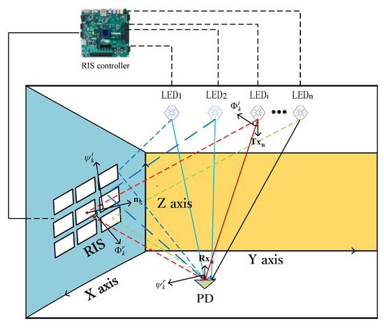
Figure 1.
RIS-aided indoor MISO-VLC system.
RIS in this scene contains identical rectangular mirrors, and the size of each element is . The center point of each mirror is located in a plane perpendicular to the y axis. Each mirror’s direction can be rotated on one’s own, and we define the angle which rotates clockwise in the positive direction of the x axis as roll angle and yaw angle to the z axis, as shown in Figure 2.
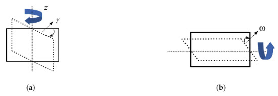
Figure 2.
(a) The mirror’s yaw rotation angle. (b) The mirror’s roll rotation angle.
According to [19], we can model the LoS process as a Lambertian model. Based on the contents in [20], we can observe that the intensity of the reflected light is significantly reduced compared with the direct light after being reflected from objects such as walls, and, consequently, can be ignored. According to the contents in [16], RIS based on mirror array can intelligently adjust the rotation angle of each mirror to change the reflection path of the optical link and realize the beamforming of the multi-mirror reflection link. Based on the derivation of RIS channel gain in [16], the RIS-aided MISO-VLC system model is expressed as:
where Y denotes the channel output, represents the channel input, n is the number of transmitters, and is additive Gaussian noise. Then, the channel input needs to meet some constraints due to the feature of VLC. The inputs should be subject to peak-power constraints:
where A is the peak-intensity constraint, the vector is the channel matrix and . Meanwhile, and are the channel gain of the LoS and NLoS path from the transmitter to the receiver, respectively. For the NLoS links, we only consider the component provided by RIS and ignore the diffused light [20]. Details of the channel gain are discussed as follows.
2.1. Channel Gain of the LoS Paths
The LoS channel gain of this model is expressed as [19]
where is the physical area of the PD, m represents the index of Lambertian model calculated by with the half-power semiangle of the LED, denotes the distance from the transmitter to the receiver, and are the angle of incidence and irradiance from the LED to the receiver, respectively. denotes the gains of the optical filter and is the optical concentrator gain towards the light from the LED. We assume the gains are constant for different LEDs. In addition, the optical concentrator gain can be expressed as [19]
where a is the refractive index at the PD and represents the field-of-view (FoV).
2.2. Channel Gain of the NLoS Paths
The NLoS paths provided by RIS can be considered as two parts: the RIS element is regarded as a receiver to accept the signals from LEDs; The RIS element is deemed to be a point source to retransmit the optical signal gathered in the previous step scaled by the reflection coefficient. We only consider first-order reflections in this paper based on the fact that high-order reflections have an unconsidered impact on VLC systems [21]. In this paper, it is assumed that the incident light from the LED is projected to the center of the mirror array element. Meanwhile, we suppose that the RIS contains K elements and the area of each element is . According to the derivation in [13], the channel gain through the RIS reflection is derived as
where is calculated according to (4), denotes the RIS element’s reflection coefficient, and we assume the coefficient of all elements is the same. represents the distance from the RIS element to the LED, denotes the distance between the RIS element and the receiver. and are the angle of irradiance and incidence from the LED to the reflective element, respectively. is the angle of irradiance from the RIS element towards the receiver, is the angle of incidence of the reflected signal from the RIS element to the receiver. The angles of irradiance and incidence are illustrated in Figure 1. Only and are charactered by the RIS element’s yaw and roll angle. It is easy to know that the norm vector of the RIS element is . The cosine of the angle of irradiance can be expressed as
where and denote the roll angle and the yaw angle of the reflective element, represents the coordinates of the RIS element where denotes the coordinates of the receiver. Similarly, the cosine of the angle of incidence can be expressed as
where denotes the transmitter’s coordinates. Consequently, the channel gain of the RIS-aided MISO-VLC channel is given by
3. Problem Formulation and Solution
In this section, the main task is to formulate an optimization problem and propose a solution to configure RIS.
3.1. Primary Problem
Moser et al. characterize the high-SNR asymptotic capacity of the IM/DD Gaussian channel model with inputs subject to peak-intensity constraints [22]. We choose the high SNR regime to analyse due to the reason that this kind of regime is the pattern of many VLC systems [23]. According to the asymptotic results derived in [24], we assume , , and the asymptotic capacity in high SNR of the RIS-aided MISO-VLC channel can be given by
where A is introduced in (2), denotes the of the vector. Note that the decision variable can only influence the NLoS channel gain produced by RIS. To maximize this improvement, according to the definition of the norm and (8), the capacity maximization problem can be equivalent to maximize the of the NLoS channel, which can be formulated as
3.2. Equivalent Problem
Since each element is independent of the other elements, we can know that
Consequently, we can maximize the NLoS gain reflected by each element to achieve the goal of capacity maximization. As for the element, the unit vector of it is , and in the following, we let (i.e., , , ). The unit vector from the element to the LED is , the unit vector from the element to the receiver is . Both of them are constant after the LED, mirror array and receiver are fixed. We assume the positions of the LED, the element and the receiver are , and . In addition, the unit vector and can be expressed as
where denotes . Combined with (5)–(7), as for the RIS element, the NLoS channel gain maximization problem is transformed into
where , denotes the inner product of vectors and , is the coefficient which is only determined by the position of the LED, the element, and the receiver. Consequently, has no concern with the decision variable. More precisely, can be calculated by
Consequently, we can solve (10) by solving K quadratic programming problems with hemispherical constraints just like (13), and adding all the results of them. Furthermore, we can transform the objective function in (13) into
we assume that , and consequently, is a matrix determined by the coordinates of LED, receiver and the RIS element. It keeps constant after fixing the position of LED, receiver and RIS. The optimization problem is transformed into
Obviously, this optimization problem can be further simplified as
Theorem 1.
Proof of Theorem 1.
First, it is convenient to be aware of the fact that the values of and are the same. Meanwhile, they are also the same as . We assume and we can get . At the same time, is a real symmetric matrix that can be diagonalized by similarity. Consequently, there exists a matrix satisfying and , where denotes identity matrix and is the eigenvalue of . Without loss of generality, we suppose that . Consequently,
we assume , and thus . Consequently, the Equation (18) can be further deduced as
the inequality becomes equal when . At the same time, is the unit eigenvector (i.e., ) corresponding to the maximum eigenvalue . This is reasonable because
Note that the constraints on (16) . The eigenvector in the dimension of can be converted to non-negative to meet the limitations. However, this operation does not change the final value. This completes the proof of Theorem 1. □
Consequently, after fixing the position of the transmitters, the receiver and RIS, the optimization problem can be solved by computing the matrix and calculating its maximum eigenvalue. At this point, the eigenvector corresponding to the maximum eigenvalue is the optimal orientation of the RIS. The process of calculating the equivalent matrix’s maximum eigenvalue and eigenvector corresponding to the eigenvalue is easy to achieve. This process can be realized by combining the functions in the MATLAB Toolbox. The maximum eigenvalue can be calculated by the functions “eig” and “max” in the MATLAB Toolbox. The eigenvector corresponding to the maximum eigenvalue is calculated by the function “eig” and the method of cyclic search. The detailed process of calcualting the maximum eigenvalue and the normalized eigenvector corresponding to it is summarized in Algorithm 1.
| Algorithm 1: The Cyclic Search Algorithm. |
| Input:
The equivalent matrix ; The dimension of the equivalent matrix ; The cyclic variable ; Output: The maximum eigenvalue ; the normalized eigenvector corresponding to ;
|
4. Simulation Results
A room model is considered with two transmitters and one PD (i.e., ). Without loss of generality, we set . This is reasonable since the noise variance can be absorbed into by normalization. In the simulation process, we normalize the channel matrix by letting each channel gain divide by the maximum channel gain . Hence, each channel gain can be given by . The maximum channel gain can be expressed as . Consequently, the maximum received power is A. Combined with the noise variance , we can consider A as the SNR in the receiver side and analyze the channel capacity. For the RIS-aided MISO-VLC system, the RIS consists of mirrors at most and the area of each mirror is at least. The normal vector of the receiver is upward towards the ceiling while the transmitters is downward towards the floor. The transmitters are fixed while the PD can be moved in the room. For comparison, we set up a scenario without RIS. Table 1 summarizes the parameters.

Table 1.
Simulation parameter.
In the simulations below, RIS elements’ orientations are adjusted adaptively according to the optimization method we proposed before. This is resonable because of two reasons. Firstly, according to the proof in the paper, the method we adopt in this paper can help the RIS-aided MISO-VLC system achieve the goal that capacity maximization. Secondly, as shown in Figure 1, based on the available information on the geometrical positioning of the PD and the LEDs, the RIS controller can send several types of instructions to the corresponding control units according to the optimization method after synthesizing the information (RIS’s position, LEDs’ position, PD’s position, etc.). Consequently, RIS can control the elements’ orientations in real time. Meanwhile, each adaptively adjustment of RIS can help the RIS-aided MISO-VLC system achieve the goal of capacity maximization.
Figure 3 shows the asymptotic capacity of the MISO-VLC channel in a high SNR scenario. In the figure, “no RIS” denotes that the received signal is only from the LoS channel, and contrastively, “RIS-aided” indicates that the received signal contains two parts: LoS channel and NLoS channel based on RIS. We set up several scenarios including different SNR to analyze the influence on adding RIS in MISO-VLC channel, and additively, we investigate the impact on the number of RIS elements. We place RIS units evenly in a rectangle to avoid the influence of other factors. In order to facilitate the analysis, the channel gain and noise variance are normalized. Since the channel model is based on the point source assumption restricting the RIS unit area to being too small [13]. We assume the minimum area of each mirror is . From this figure, we can observe that RIS can improve capacity performance and the capability enchances with the number of RIS elements. What’s more, we can know that the capacity improvement is no longer significant when K is large enough. This is due to the marginal benefit and the constraints on the model’s assumption. The results show that asymptotic capacity has been dramatically improved with the assistance of RIS due to the ability to provide a large improvement in the channel gain. Table 2 summarizes the numerical results in the channel domain. The proportion represents the ratio of the NLoS channel gain to the LoS channel gain.
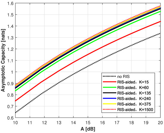
Figure 3.
Asymptotic capacity of MISO-VLC channel in High-SNR scenario versus SNR with different number of mirrors.
Table 2.
Numerical values of LoS and NLoS links with different K.
Figure 4 shows the asymptotic capacity of the MISO-VLC channel in a high SNR scenario. We can observe that the degree of the performance improvement decreases with the number of mirrors. This is due to the marginal benefit and the constraints on the model’s assumption. The results show that asymptotic capacity has been improved with the assistance of RIS due to the ability to provide a large improvement in the channel gain.
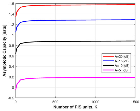
Figure 4.
Asymptotic capacity of MISO-VLC channel in High-SNR scenario versus number of mirrors with different SNR.
The asymptotic capacity of the MISO-VLC channel in each position of the room was investigated. Figure 5 indicates the influence of the horizontal distance between the receiver and RIS. In this scenario, we consider a fixed and to compare the capacity in different positions between “no RIS” and “RIS-aided”. We fix the positions of the transmitters and place them symmetrically between the center of the ceiling. Meanwhile, we mobile the receiver in one direction. We suppose that the performance improvement is denoted by the growth rate shown in Figure 5, which can be calculated by the quotient of the capacity provided by RIS and the capacity provided by the LoS channel. It can be observed that the RIS-aided MISO-VLC system earns superb capacity performance in contrast with the system without RIS, even up to gain. We find that the closer the receiver is to the RIS, the more obvious the performance improvement. The results bring us guidance for deploying RIS in the future. Owing to the constraint, we only deploy RIS on one wall, and the performance may be better if we adopt an appropriate deployment scheme such as deploying RIS on four walls or distributing RIS more uniform on one wall.
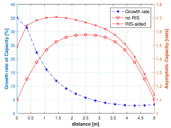
Figure 5.
Asymptotic capacity and growth versus horizontal distance between receiver and RIS.
To analyze the influence of the RIS deployment scheme on capacity improvement, we make several simulations given a certain number of mirrors. Figure 6 displays the asymptotic capacity performance under the circumstance of . In order to investigate the influence of RIS, we assume that the transmitters and the receiver are fixed. We divide the RIS into 150 mirrors and organize them in different ways (e.g., , , ). Where the former denotes the number of rows while the latter represents the number of columns. In the process of simulation, RIS units are fixed in a rectangle.
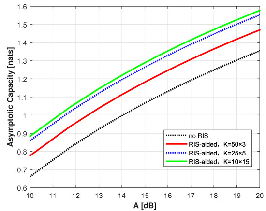
Figure 6.
Asymptotic capacity versus deployment of RIS.
It can be known from the figure that the more uniform you lay RIS out, the better performance you can obtain. Consequently, we can further examine how RIS can be deployed within a limited area of the wall to maximize performance gains in the future. Table 3 summarizes the numerical results in the channel domain. The proportion represents the ratio of the NLoS channel gain to the LoS channel gain.
Table 3.
Numerical Values of LoS and NLoS links with different deployment of RIS.
5. Discussion
In this paper, we construct a novel indoor RIS-aided MISO-VLC system. Compared with the prior research works on SISO-VLC systems [10,16,17,18,25], applying RIS to MISO-VLC system is our innovation. For the RIS-aided MISO-VLC system based on mirror array, we formulate an asymptotic capacity maximization problem to find the optimal orientations of mirrors. Different traditional solutions (e.g., heuristic algorithm [16,18], assuming that all mirrors have identical angles [18]) to solve the non-convex optimization problem, we convert it into a quadratic programming (QP) problem with hemispherical constraints and prove that it can be solved by computing the maximum eigenvalue of an equivalent matrix. This method can help us calculating the optimal configuration of RIS and has low complexity. Meanwhile, we investigate the influence of RIS deployment and the distance between RIS and the receiver on performance improvement. As far as we know, there is no literature in this area, and the investigation will guide our research work on RIS deployment in the future.
6. Conclusions
In the paper, a RIS-aided MISO-VLC channel is modeled. We consider the asymptotic capacity maximization as an optimization problem and provide appropriate deployment schemes of RIS. As for this non-convex optimization problem, we adopt an efficient solution to transform the complex problem into an equivalent problem which is easy to solve. Simulation results reveal that integrating RIS in the MISO-VLC channel can enchance the asymptotic capacity in high SNR scenarios, and the deployment scheme of RIS may influence the degree of performance improvement. The number of the mirrors can influence the degree of the performance. With the increase of the number of mirrors, the performance of VLC systems can be improved. However, when the number of mirrors is large enough, the degree of the performance improvement provided by RIS is not obvious. Meanwhile, through the simulation results, we find that the deployment of RIS is another influence factor for the performance improvement. The closer the receiver is to the RIS and the more uniform RIS is laid out, the more obvious the performance improvement. Hence, RIS should be a prospective solution to improve the capacity in VLC systems and we will investigate the deployment of RIS in the future to enhance the performance provided by RIS.
Author Contributions
Conceptualization, Q.W.; methodology, J.G.; software, Q.W.; validation, Q.W.; formal analysis, Q.W.; investigation, Q.W.; resources, Q.W.; data curation, J.G.; writing—original draft preparation, Q.W.; writing—review and editing, J.Z.; visualization, Q.W.; supervision, J.Z.; project administration, J.Z.; funding acquisition, J.Z. All authors have read and agreed to the published version of the manuscript.
Funding
This research was supported by the National Natural Science Foundation of China (NSFC) under Grant (62071489) and the National Key Research and Development Project (2018YFB1801903).
Institutional Review Board Statement
Not applicable.
Informed Consent Statement
Not applicable.
Data Availability Statement
Not applicable.
Acknowledgments
The author acknowledges Ruhan Chen’s help to find the topic of optical RIS and contribution in Section 3.2. Meanwhile, Ruhan Chen has contribution in polishing the language and finding the defect of format of this paper.
Conflicts of Interest
The authors declare no conflict of interest.
References
- Pathak, P.H.; Feng, X.; Hu, P.; Mohapatra, P. Visible light communication, networking, and sensing: A survey, potential and challenges. IEEE Commun. Surv. Tutorials 2015, 17, 2047–2077. [Google Scholar] [CrossRef]
- Kartalopoulos, S.V. Free Space Optical Networks for Ultra-Broad Band Services; John Wiley & Sons: Hoboken, NJ, USA, 2011. [Google Scholar]
- Kahn, J.M.; Barry, J.R. Wireless infrared communications. Proc. IEEE 1997, 85, 265–298. [Google Scholar] [CrossRef] [Green Version]
- Chaaban, A.; Rezki, Z.; Alouini, M.S. On the capacity of intensity-modulation direct-detection Gaussian optical wireless communication channels: A tutorial. IEEE Commun. Surv. Tutorials 2021, 24. [Google Scholar] [CrossRef]
- Li, L.; Moser, S.M.; Wang, L.; Wigger, M. On the capacity of MIMO optical wireless channels. IEEE Trans. Inf. Theory 2020, 66, 5660–5682. [Google Scholar] [CrossRef] [Green Version]
- Hranilovic, S.; Kschischang, F.R. Capacity bounds for power-and band-limited optical intensity channels corrupted by Gaussian noise. IEEE Trans. Inf. Theory 2004, 50, 784–795. [Google Scholar] [CrossRef]
- Chaaban, A.; Rezki, Z.; Alouini, M.S. Capacity bounds and high-SNR capacity of MIMO intensity-modulation optical channels. IEEE Trans. Wirel. Commun. 2018, 17, 3003–3017. [Google Scholar] [CrossRef] [Green Version]
- Liu, Y.; Liu, X.; Mu, X.; Hou, T.; Xu, J.; Di Renzo, M.; Al-Dhahir, N. Reconfigurable intelligent surfaces: Principles and opportunities. IEEE Commun. Surv. Tutorials 2021, 23, 1546–1577. [Google Scholar] [CrossRef]
- Wu, Q.; Zhang, R. Towards smart and reconfigurable environment: Intelligent reflecting surface aided wireless network. IEEE Commun. Mag. 2019, 58, 106–112. [Google Scholar] [CrossRef] [Green Version]
- Sun, S.; Yang, F.; Song, J. Sum rate maximization for intelligent reflecting surface-aided visible light communications. IEEE Commun. Lett. 2021, 25, 3619–3623. [Google Scholar] [CrossRef]
- Wang, H.; Zhang, Z.; Zhu, B.; Dang, J.; Wu, L.; Wang, L.; Zhang, K.; Zhang, Y. Performance of wireless optical communication with reconfigurable intelligent surfaces and random obstacles. arXiv 2020, arXiv:2001.05715. [Google Scholar]
- Najafi, M.; Schmauss, B.; Schober, R. Intelligent reflecting surfaces for free space optical communication systems. IEEE Trans. Commun. 2021, 69, 6134–6151. [Google Scholar] [CrossRef]
- Abdelhady, A.M.; Salem, A.K.S.; Amin, O.; Shihada, B.; Alouini, M.S. Visible light communications via intelligent reflecting surfaces: Metasurfaces vs mirror arrays. IEEE Open J. Commun. Soc. 2020, 2, 1–20. [Google Scholar] [CrossRef]
- Shirmanesh, G.K.; Sokhoyan, R.; Wu, P.C.; Atwater, H.A. Electro-optically tunable multifunctional metasurfaces. ACS Nano 2020, 14, 6912–6920. [Google Scholar] [CrossRef] [PubMed]
- Hu, Y.; Ou, X.; Zeng, T.; Lai, J.; Zhang, J.; Li, X.; Luo, X.; Li, L.; Fan, F.; Duan, H. Electrically tunable multifunctional polarization-dependent metasurfaces integrated with liquid crystals in the visible region. Nano Lett. 2021, 21, 4554–4562. [Google Scholar] [CrossRef] [PubMed]
- Qian, L.; Chi, X.; Zhao, L.; Chaaban, A. Secure visible light communications via intelligent reflecting surfaces. In Proceedings of the ICC 2021-IEEE International Conference on Communications, Montreal, QC, Canada, 14–23 June 2021; pp. 1–6. [Google Scholar]
- Cao, B.; Chen, M.; Yang, Z.; Zhang, M.; Zhao, J.; Chen, M. Reflecting the light: Energy efficient visible light communication with reconfigurable intelligent surface. In Proceedings of the 2020 IEEE 92nd Vehicular Technology Conference (VTC2020-Fall), Virtual, 18 November–16 December 2020; pp. 1–5. [Google Scholar]
- Aboagye, S.; Ngatched, T.M.; Dobre, O.A.; Ndjiongue, A.R. Intelligent reflecting surface-aided indoor visible light communication systems. IEEE Commun. Lett. 2021, 25, 3913–3917. [Google Scholar] [CrossRef]
- Komine, T.; Nakagawa, M. Fundamental analysis for visible-light communication system using LED lights. IEEE Trans. Consum. Electron. 2004, 50, 100–107. [Google Scholar] [CrossRef]
- Barry, J.R.; Kahn, J.M.; Krause, W.J.; Lee, E.A.; Messerschmitt, D.G. Simulation of multipath impulse response for indoor wireless optical channels. IEEE J. Sel. Areas Commun. 1993, 11, 367–379. [Google Scholar] [CrossRef] [Green Version]
- Tang, T.; Shang, T.; Li, Q. Impact of multiple shadows on visible light communication channel. IEEE Commun. Lett. 2020, 25, 513–517. [Google Scholar] [CrossRef]
- Lapidoth, A.; Moser, S.M.; Wigger, M.A. On the capacity of free-space optical intensity channels. IEEE Trans. Inf. Theory 2009, 55, 4449–4461. [Google Scholar] [CrossRef] [Green Version]
- Kazemi, H.; Haas, H. Downlink cooperation with fractional frequency reuse in DCO-OFDMA optical attocell networks. In Proceedings of the 2016 IEEE International Conference on Communications (ICC), Kuala Lumpur, Malaysia, 22–27 May 2016; pp. 1–6. [Google Scholar]
- Moser, S.M.; Wang, L.; Wigger, M. Capacity results on multiple-input single-output wireless optical channels. IEEE Trans. Inf. Theory 2018, 64, 6954–6966. [Google Scholar] [CrossRef] [Green Version]
- Sun, S.; Yang, F.; Song, J.; Han, Z. Joint resource management for intelligent reflecting surface-aided visible light communications. IEEE Trans. Wirel. Commun. 2022. [Google Scholar] [CrossRef]
Publisher’s Note: MDPI stays neutral with regard to jurisdictional claims in published maps and institutional affiliations. |
© 2022 by the authors. Licensee MDPI, Basel, Switzerland. This article is an open access article distributed under the terms and conditions of the Creative Commons Attribution (CC BY) license (https://creativecommons.org/licenses/by/4.0/).