Abstract
The orbital angular momentum (OAM) holography has been marked a path to achieving ultrahigh capacity holographic information systems. However, the practical applicability of the OAM holography is limited by the complicated optical setup and unadjustable image intensity and position. Here, a decoding method is proposed by using a binarized phase map derived from an autofocusing Airy beam. By adjusting the parameters of the phase map, the position and intensity distribution of the reconstructed image become flexibly adjustable. In addition, the cross-talk between different image channels can be effectively reduced thanks to the abruptly autofocusing capability of the Airy beams. As a result, the quality and practicability of the OAM holography can be greatly enhanced.
1. Introduction
Holography was proposed by Dennis Gabor in 1948, and it provides a way to reconstruct the amplitude and phase information of a 3D object [1]. Up to now, holography has been widely used in the fields of optical display [2,3], optical manipulation [4], optical communications [5,6,7], optical encryption [8,9,10] and machine learning [11,12]. Recently, the OAM holography proposed by Gu et al. has been identified as a vital platform for achieving ultrahigh-capacity holographic multiplexation and high-security encryption without a theoretical limit of helical mode index [9]. After that, complex-amplitude metasurface-based OAM holography [13], polarization-encrypted OAM metasurface holography [10], modulated OAM holography [14], and high-dimensional nonlinear holography [15,16] have been proposed, which paves the way for optical communication, optical storage, and ultrahigh-security optical encryption.
However, in the work mentioned above, a Fourier lens with a specific focal length should be placed behind the hologram to reconstruct the desired image at a given plane. The lens needs to be changed when adjusting the reconstruction distance. In addition, when changing the image intensity, the laser power or the optical attenuation devices should be manually adjusted. The complicated optical setup and unadjustable position and intensity of the reconstructed images limit the flexible application of conventional OAM holography. Although a programmable phase lens can be used to adjust the reconstruction distance [13], there exists severe cross-talk between different OAM modes, which degrades the quality of the reconstructed images.
Abruptly autofocusing beams have attracted lots of interest in the last decades because these beams can autofocus during propagation, and the peak intensity at the focal plane can increase by several orders of magnitude [17,18,19]. An example of such beams is the circular Airy beam [17]. The abruptly autofocusing property makes these beams applicable in many areas, including biomedical treatment [17], optical manipulation [20,21,22], light bullets [23] and so on.
Based on the abruptly autofocusing beams, we develop a binarized phase lens and apply it to the OAM holography; then, the reconstruction distance and intensity are made adjustable. The rest of the paper is organized as follows. The theoretical explanation of flexible decoding is presented in Section 2. A decoding experiment is presented in Section 3, and the paper is summarized in Section 4.
2. Principle and Implementation
An Airy beam can be expressed as [18,24],
where A0 is the amplitude of the input electric field, Ai(∙) represents the Airy function, r0 is a radius constant, w is a scaling coefficient, a is a decay factor, r = sqrt(x2 + y2) denotes the radial coordinate, and x and y are the abscissa coordinates. The electric field is shown in Figure 1a. This beam can abruptly focus during propagation, while the peak intensity can be increased by several orders of magnitude [17,19].
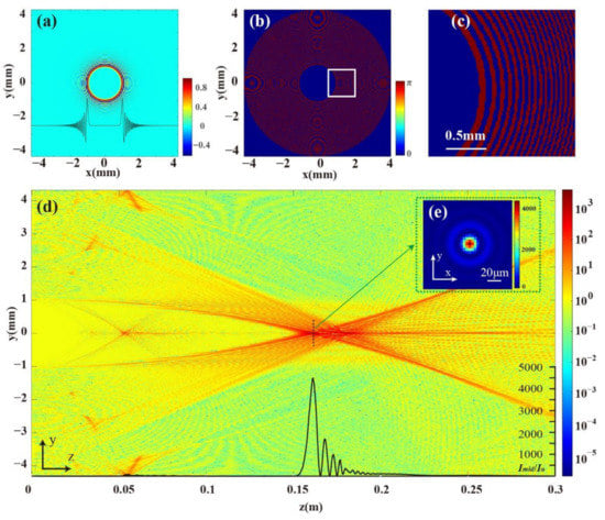
Figure 1.
Propagation properties of eiBp(x, y). (a) The initial electric field of a circular Airy beam. (b) The Bp phase map. (c) Partial detail of (b). (d) The side view of the beam propagation at the y–z plane. (e) The relative intensity distribution of the focal spot.
We introduce the binarized phase Bp
which can be called a “binarized Airy lens” (BAL).
Theoretically, an OAM hologram encoded by multiple image channels can be expressed as [9], where N presents the number of image channels, φ is the azimuth angle, and Hn is the n-th image channel, which is obtained by the inverse Fourier transform on the sampled target image [1]. When the m-th image channel Hm needs to be decoded, a beam with lde = −lm is used to illuminate the OAM multiplexing hologram, and the resulting electric distribution can be expressed as
After a transmission distance, the electric distribution at an arbitrary position can be expressed as
where denotes the Fourier transform, represents the diffraction operator and * is a convolution operator. The term (Hm) * (eiBp) can be converted into quasi-Gaussian spots at the focal plane, which yields a desired spot-pattern image. As for the other channels in the latter term, each spot is converted into a doughnut-shaped structure with much lower intensity, which can be regarded as background. The term with lde = −lm can be regarded as the decoding BAL mode here. As a result, the reconstruction result is determined by the evolution of eiBp(x, y).
Under the framework of paraxial approximation, the evolution of a slowly varying envelope uBp(x, y) = eiBp(x, y) can be described by angular spectrum theory [25]. The calculation results of the propagation of uBp(x, y, z) with the settings of r0 = 1 mm, w = 4 × 10⁻⁵, a = 0.1, and λ = 632.8 nm are shown in Figure 1. According to the specifications of the spatial light modulator (SLM), the diameter of the beam is set to be 8.64 mm, the pixel size is 8 μm, and the number of pixels is 1080 × 1080. A planar beam carrying a BAL can abruptly autofocus during propagation, and the peak intensity can be increased by about 4.5 × 10³ times the initial intensity, which shows a much stronger focusing capability (Figure 1). Notably, this beam has secondary foci (Figure 2a,b), which can be calculated as fm = f1/(2m − 1), and f1 is the primary focal length. But the secondary foci can be weakened or eliminated by altering the parameters r0 and w.
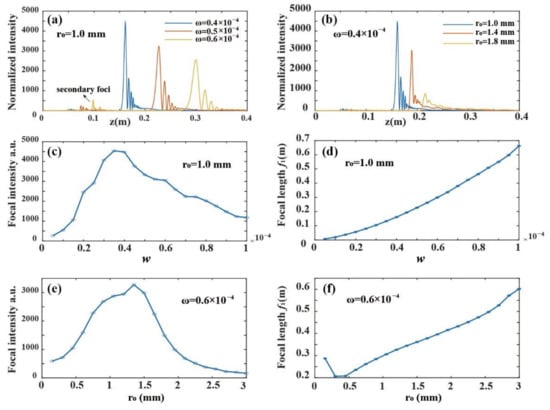
Figure 2.
Adjustable focal length and focal intensity. (a) The peak intensity as a function of z with different w at r0 = 1 mm; (b) The peak intensity as a function of z with different r0 at w = 0.4 × 10⁻⁴. (c) The focal intensity as a function of w. (d) The focal length as a function of w. (e) The focal intensity as a function of r0. (f) The focal length is a function of r0.
Moreover, The focal length and intensity of uBp(x, y) at the focal plane can be easily adjusted by changing the parameters r0 and w, as shown in Figure 2a,b. For example, when r0 = 1.0 mm, the relationships of Imax − w and f1−w are provided in Figure 2c,d, where Imax and f1 are the peak intensity and focal length, respectively. As the scaling factor w increases, the peak intensity will increase gradually and then degrease (Figure 2c). Meantime, the focal length will increase gradually (Figure 2d). They are fitted quantitatively as
In addition, the radius r0 can affect the focal intensity and focal length when w is fixed (Figure 2e,f). The desired intensity and focal length of the kernel function can be obtained by choosing suitable parameters w and r0. Due to the convolution relationship between the adjustable kernel function and target image, the reconstruction distance and image intensity can thus be flexibly controlled.
Simulation is then conducted to compare the signal-to-noise ratios between the proposed decoding method and the traditional method [9] by setting the pixel number 1080 × 1080, the pixel size 8 μm, and the hologram size 8.64 mm, as shown in Figure 3. Under the encoded helical difference Δl = 5 and r0 = 1 mm, the radio can achieve 8.2 dB, while the traditional decoding method can only achieve about 4.39 dB (Table 1). A greater interval Δl can enhance the reconstruction of SNR in both cases. However, the BAL decoding method can improve by about 2.5 dB when the encoded helical difference Δl is 10. Thus, the new decoding method not only makes the reconstruction distance and intensity adjustable but also improves the image quality. In the traditional decoding method, the doughnut-shaped cross-talk is determined by the index difference of encoded helical phase modes [9]. However, in the proposed method, the reconstruction quality is determined by the autofocusing capability of the BAL beam, which is associated with the parameter w (Figure 2).
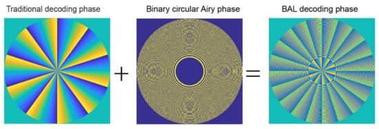
Figure 3.
Comparison of traditional and BAL decoding phases.

Table 1.
Numerical comparison of the reconstruction SNR of different decoding methods.
3. Experimental Demonstration
An OAM-multiplexing hologram is designed and sampled as discrete spots in its spatial frequency domain to conduct an experimental demonstration. Figure 4 illustrates the design procedure of a hologram. For example, three target images, namely letters ‘F’, ‘D’ and ‘U’ of SF Square Head font with 1080 × 1080 pixels, are used to generate a hologram. Three helical phase modes with l = −10, 10, and 20 are adopted for encoding. The sampling constant is 40 pixels in the experiment. Three OAM holograms can be generated by conducting an iterative inverse Fourier transform on the sampled target images [9,26]. By combining the three holograms into one, an OAM-multiplexing hologram can be finally obtained, as shown in Figure 4b.
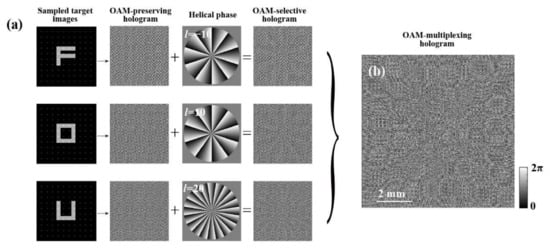
Figure 4.
Generation of an OAM-multiplexing hologram. (a) The design procedure. (b) The generated hologram.
An experimental system is built to demonstrate the image reconstruction at different distances, as shown in Figure 5a. A He-Ne laser with a central wavelength of 632.8 nm is applied as the light source. The laser passes through a half-wave plate and a polarizer to ensure that the polarization direction of the beam is consistent with the spatial light modulator (SLM). After passing through a beam splitter, the beam arrives at an SLM Holoeye PLUTO-NIR-011 with 1080 × 1920 pixels and a pixel size of 8 μm. After being modulated by the SLM and passing through a polarizer, the beam arrives at a CCD with 2048 × 2048 pixels and a pixel size of 5.5 μm. The polarizer in this step can filter out unwanted polarized light except for the modulating one, which improves the reconstruction quality.
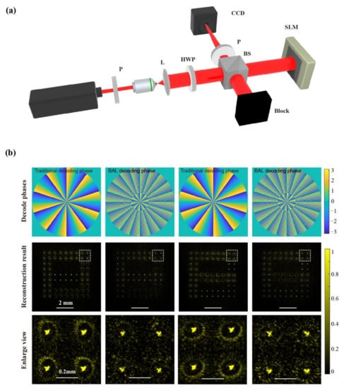
Figure 5.
Experimental implementation. (a) Optical setup. P: linear polarizer; L: lens; BS: beam splitter; HWP: half-wave plate. (b) Decoding the OAM multiplexing hologram with traditional and BAL decoding methods with the same exposure time, the top row of pictures is the decoding phase, and the following two lines of pictures are the decoding results.
Two letters, ‘F’ and ‘D,’ are used to design the OAM multiplexing hologram with the encoded helical phase index 10 and −10. The reconstruction results of this method and the traditional method are depicted in Figure 5b. Clearly, the doughnut-shaped cross-talk remaining in the reconstruction image can be suppressed greatly. Moreover, the focal length can be flexibly controlled by adjusting the parameter of the BAL phase map, as shown in Figure 6. By using three decoding BAL phases with distinct parameters w = 0.58 × 10⁻⁴, w = 0.60 × 10⁻⁴, and w = 0.62 × 10⁻⁴, three images can be reconstructed with high quality and great stability at different distances of 0.300 m, 0.315 m, and 0.330 m, respectively (bottom of Figure 6b). It is worth noting that the image magnification gradually increases as the reconstruction distance increases. The size of the reconstructed image ‘U’ is about 1.08 times that of ‘F’. When decoding one image channel of the OAM multiplexing hologram, the desired reconstruction image suffers from cross-talk with the other two image channels. In addition, due to the light intensity oscillations behind the focal plane (Figure 1 and Figure 2), several secondary focal planes occur. Therefore, the primary reconstruction distance should be chosen in practical applications to avoid cross-talks in the reconstruction images.
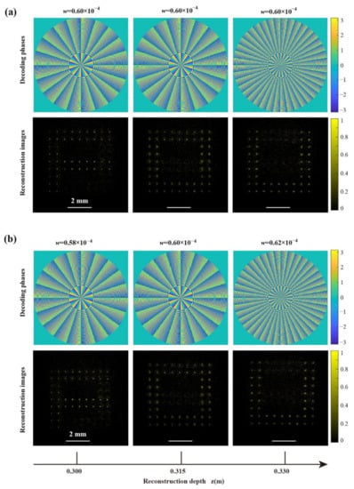
Figure 6.
Decoding the OAM multiplexing hologram by BAL method. (a) Reconstruction results at a distance of 0.315 m. (b) Reconstruction results at different distances by adjusting BAL parameters.
4. Discussion
By employing a circular Airy beam for image decoding, the image position and intensity of the reconstructed images are made flexibly controllable by adjusting the BAL parameters. On the one hand, the doughnut-shaped cross-talk can be suppressed thanks to the autofocusing property of the BAL beam greatly.
The SNR of the BAL decoding method is influenced by the parameters w, r0 and the difference of the helical phase indices Δl = ln − ln−1. At r0 = 1 mm, the SNR will decrease first and then increase gradually as w increases (Figure 7). However, when w > 0.5 × 10⁻⁴, the reconstruction SNR can be improved by about 2dB compared to the conventional method. Notably, a smaller scaling coefficient w will cause greater background intensity and oscillation variation, leading to a much lower reconstruction SNR. Therefore, a greater w is preferred in terms of SNR. In addition, the BAL phase is directly imposed on the OAM multiplexing hologram for decoding; thus, the quality of reconstructed images is not worsened when the encoded helical index increases.
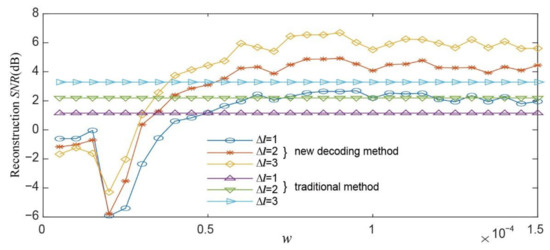
Figure 7.
Comparisons of SNR of different decoding methods.
It should be emphasized that as the intensity distributions of the BAL phase mode and the traditional helical phase mode have the same diameter, the OAM hologram does not need to be redesigned, and the image reconstruction can be directly conducted on the conventional OAM hologram. But interestingly, the BAL decoding method provides a more universal approach for image decoding, which will enhance the flexible applications of the OAM holography.
5. Conclusions
In summary, a method of decoding OAM holograms with a binarized Airy lens is proposed and experimentally demonstrated. By changing the parameters of this binarized phase map, the reconstruction distance and image intensity can be adjusted flexibly. In addition, the cross-talk between different OAM modes can be effectively suppressed. As a result, the proposed decoding method will enhance the practicability of the OAM holography. The decoding method will find widespread applications in 3D displays, image reconstruction [27,28,29], optical manipulation [4], optical trapping [21,30,31], biomedical treatment [17], super-resolution microscopy [32] and so on. Future research will be focused on the layer-by-layer reconstruction of three-dimensional objects by using the BAL method, and the high-quality image reconstruction of the OAM holography in the turbulent media or obscured objects will be investigated as well.
Author Contributions
Conceptualization, F.W. and X.Z.; writing—original draft preparation, F.W. and X.Z.; writing—review and editing, F.W., X.Z., R.X., X.M., H.Y., L.L. and X.J.; supervision, X.Z.; funding acquisition, X.Z. All authors have read and agreed to the published version of the manuscript.
Funding
This research was funded in part by the National Natural Science Foundation of China under Grant 51875107, partly by the Key Research and Development Program of Jiangsu Province under Grant BE2021035, and partly by the SAST Fund under Grant 2019-086.
Data Availability Statement
Data underlying the results presented in this paper are not publicly available at this time but may be obtained from the authors upon reasonable request.
Conflicts of Interest
The authors declare no conflict of interest.
References
- Gabor, D. A New Microscopic Principle. Nature 1948, 161, 777–778. [Google Scholar] [CrossRef] [PubMed]
- Downing, E.; Hesselink, L.; Ralston, J.; Macfarlane, R. A Three-Color, Solid-State, Three-Dimensional Display. Science 1996, 273, 1185–1189. [Google Scholar] [CrossRef]
- Tay, S.; Blanche, P.A.; Voorakaranam, R.; Tunç, A.V.; Lin, W.; Rokutanda, S.; Gu, T.; Flores, D.; Wang, P.; Li, G.; et al. An Updatable Holographic Three-Dimensional Display. Nature 2008, 451, 694–698. [Google Scholar] [CrossRef] [PubMed]
- Grier, D.G. A Revolution in Optical Manipulation. Nature 2003, 424, 810–816. [Google Scholar] [CrossRef]
- Wang, J.; Yang, J.Y.; Fazal, I.M.; Ahmed, N.; Yan, Y.; Huang, H.; Ren, Y.; Yue, Y.; Dolinar, S.; Tur, M.; et al. Terabit Free-Space Data Transmission Employing Orbital Angular Momentum Multiplexing. Nat. Photonics 2012, 6, 488–496. [Google Scholar] [CrossRef]
- Willner, A.E.; Huang, H.; Yan, Y.; Ren, Y.; Ahmed, N.; Xie, G.; Bao, C.; Li, L.; Cao, Y.; Zhao, Z.; et al. Optical Communications Using Orbital Angular Momentum Beams. Adv. Opt. Photonics 2015, 7, 66–106. [Google Scholar] [CrossRef] [Green Version]
- Yao, A.M.; Padgett, M.J. Orbital Angular Momentum: Origins, Behavior and Applications. Adv. Opt. Photonics 2011, 3, 161–204. [Google Scholar] [CrossRef] [Green Version]
- Ren, H.; Briere, G.; Fang, X.; Ni, P.; Sawant, R.; Héron, S.; Chenot, S.; Vézian, S.; Damilano, B.; Brändli, V.; et al. Metasurface Orbital Angular Momentum Holography. Nat. Commun. 2019, 10, 102–108. [Google Scholar] [CrossRef]
- Fang, X.; Ren, H.; Gu, M. Orbital Angular Momentum Holography for High-Security Encryption. Nat. Photonics 2020, 14, 102–108. [Google Scholar] [CrossRef]
- Zhou, H.; Sain, B.; Wang, Y.; Schlickriede, C.; Zhao, R.; Zhang, X.; Wei, Q.; Li, X.; Huang, L.; Zentgraf, T. Polarization-Encrypted Orbital Angular Momentum Multiplexed Metasurface Holography. ACS Nano 2020, 14, 5553–5559. [Google Scholar] [CrossRef]
- Ren, H.; Shao, W.; Li, Y.; Salim, F.; Gu, M. Three-Dimensional Vectorial Holography Based on Machine Learning Inverse Design. Sci. Adv. 2020, 6, eaaz4261. [Google Scholar] [CrossRef] [PubMed] [Green Version]
- Gu, M.; Fang, X.; Ren, H.; Goi, E. Optically Digitalized Holography: A Perspective for All-Optical Machine Learning. Engineering 2019, 5, 363–365. [Google Scholar] [CrossRef]
- Ren, H.; Fang, X.; Jang, J.; Bürger, J.; Rho, J.; Maier, S.A. Complex-Amplitude Metasurface-Based Orbital Angular Momentum Holography in Momentum Space. Nat. Nanotechnol. 2020, 15, 948–955. [Google Scholar] [CrossRef] [PubMed]
- Wang, F.; Zhang, X.; Yuan, H.; Xiong, R.; Jiang, X. Enhancing the Information Capacity with Modulated Orbital Angular Momentum Holography. IEEE Photonics J. 2022, 14, 3146189. [Google Scholar] [CrossRef]
- Fang, X.; Wang, H.; Yang, H.; Ye, Z.; Wang, Y.; Zhang, Y.; Hu, X.; Zhu, S.; Xiao, M. Multichannel Nonlinear Holography in a Two-Dimensional Nonlinear Photonic Crystal. Phys. Rev. A 2020, 102, 43506. [Google Scholar] [CrossRef]
- Fang, X.; Yang, H.; Yao, W.; Wang, T.; Zhang, Y.; Gu, M.; Xiao, M. High-Dimensional Orbital Angular Momentum Multiplexing Nonlinear Holography. Adv. Photonics 2021, 3, 015001. [Google Scholar] [CrossRef]
- Efremidis, N.K.; Christodoulides, D.N. Abruptly Autofocusing Waves. Opt. Lett. 2010, 35, 4045–4047. [Google Scholar] [CrossRef]
- Efremidis, N.K.; Chen, Z.; Segev, M.; Christodoulides, D.N. Airy Beams and Accelerating Waves: An Overview of Recent Advances. Optica 2019, 6, 686–701. [Google Scholar] [CrossRef] [Green Version]
- Jiang, Y.; Huang, K.; Lu, X. Propagation Dynamics of Abruptly Autofocusing Airy Beams with Optical Vortices. Opt. Express 2012, 20, 18579–18584. [Google Scholar] [CrossRef]
- Chremmos, I.; Zhang, P.; Prakash, J.; Efremidis, N.K.; Christodoulides, D.N.; Chen, Z. Fourier-Space Generation of Abruptly Autofocusing Beams and Optical Bottle Beams. Opt. Lett. 2011, 36, 3675–3677. [Google Scholar] [CrossRef]
- Zhang, P.; Prakash, J.; Zhang, Z.; Mills, M.S.; Efremidis, N.K.; Christodoulides, D.N.; Chen, Z. Trapping and Guiding Microparticles with Morphing Autofocusing Airy Beams. Opt. Lett. 2011, 36, 2883–2885. [Google Scholar] [CrossRef]
- Jiang, Y.; Huang, K.; Lu, X. Radiation Force of Abruptly Autofocusing Airy Beams on a Rayleigh Particle. Opt. Express 2013, 21, 24413–24421. [Google Scholar] [CrossRef]
- Panagiotopoulos, P.; Papazoglou, D.G.; Couairon, A.; Tzortzakis, S. Sharply Autofocused Ring-Airy Beams Transforming into Non-Linear Intense Light Bullets. Nat. Commun. 2013, 4, 2622. [Google Scholar] [CrossRef] [Green Version]
- Jiang, Y.; Zhu, X.; Yu, W.; Shao, H.; Zheng, W.; Lu, X. Propagation Characteristics of the Modified Circular Airy Beam. Opt. Express 2015, 23, 29834–29841. [Google Scholar] [CrossRef]
- Shen, D.; Zhao, D. Measuring the Topological Charge of Optical Vortices with a Twisting Phase. Opt. Lett. 2019, 44, 2334–2337. [Google Scholar] [CrossRef]
- Gerchberg, R.W.; Saxton, W. A Practical Algorithm for the Determination of Phase from Image and Diffraction Plane Pictures. Optik 1971, 35, 237–250. [Google Scholar]
- Dan, D.; Wang, Z.; Zhou, X.; Lei, M.; Zhao, T.; Qian, J.; Yu, X.; Yan, S.; Min, J.; Bianco, P.R.; et al. Rapid Image Reconstruction of Structured Illumination Microscopy Directly in the Spatial Domain. IEEE Photonics J. 2021, 13, 3900411. [Google Scholar] [CrossRef]
- Lei, X.; Ma, X.; Yang, Z.; Peng, X.; Yun, L.; Zhao, M.; Fan, M. Improving Compressed Sensing Image Reconstruction Based on Atmospheric Modulation Using the Distributed Cumulative Synthesis Method. IEEE Photonics J. 2021, 13, 3108194. [Google Scholar] [CrossRef]
- Liu, Z.; Shen, C.; Tan, J.; Liu, S. A Recovery Method of Double Random Phase Encoding System with a Parallel Phase Retrieval. IEEE Photonics J. 2016, 8, 2527699. [Google Scholar] [CrossRef]
- Gahagan, K.T.; Swartzlander, G.A. Optical Vortex Trapping of Particles. Opt. Lett. 1996, 21, 827–829. [Google Scholar] [CrossRef]
- Ng, J.; Lin, Z.; Chan, C.T. Theory of Optical Trapping by an Optical Vortex Beam. Phys. Rev. Lett. 2010, 104, 103601. [Google Scholar] [CrossRef] [Green Version]
- Jia, S.; Vaughan, J.C.; Zhuang, X. Isotropic Three-Dimensional Super-Resolution Imaging with a Self-Bending Point Spread Function. Nat. Photonics 2014, 8, 302–306. [Google Scholar] [CrossRef] [Green Version]
Publisher’s Note: MDPI stays neutral with regard to jurisdictional claims in published maps and institutional affiliations. |
© 2022 by the authors. Licensee MDPI, Basel, Switzerland. This article is an open access article distributed under the terms and conditions of the Creative Commons Attribution (CC BY) license (https://creativecommons.org/licenses/by/4.0/).