2. RDE Induced by a Rotating Vortex Optical Beam
The RDE was first demonstrated based on the rotation of a circularly polarized beam with spin angular momentum (SAM). In 1981, Garetz attributed the frequency shift previously observed as a rotating half-wave plate [
9] to a special Doppler effect, named the angular Doppler effect [
10]. In 1992, Allen, et al. demonstrated a vortex beam with an azimuthal phase distribution as
eilφ, such as the nonzero-order Laguerre–Gaussian (LG) laser mode [
11]. A vortex beam exhibits the orbital angular momentum (OAM) of
in per photon, where
l is the topological charge,
φ is the azimuth, and
is the reduced Planck constant. The vortex beam has a spiral wave front, with a phase singularity on the axis and a typical intensity distribution of concentric rings [
12]. Soon after, in 1996, Nienhuis predicted that a rotating mode converter that consists of three parallel cylindrical lenses could change the sense of the OAM, as well as the frequency of the beam [
13]. It was demonstrated theoretically that a LG beam with mode number
l can form a frequency difference of 2
lΩ after passing through a mode converter with the rotation speed Ω, which also indicates the potential of a vortex beam to detect rotational motion. Courtial, et al. carried out experiments by rotating the millimeter wave beam based on a rotating Dove prism in 1998 [
14,
15]. As shown in
Figure 1, the interference beam coming from the superposition of two vortex beams passing the stationary and rotating prism exhibits a periodic change of intensity because of the additional frequency shift induced by the rotating the vortex beam. The rotation of the beam will change the number of wave fronts passing through a certain plane in a unit of time by the parameter of
l. Hence, the frequency shift is simply equal to
lΩ. They also showed that both the OAM and SAM can influence the rotational frequency shift as ∆ω = (
l + σ)Ω, where σ = ±1 corresponds to the left- and right-handed circularly polarized light.
In addition to rotating the Dove prism, I.V. Basistiy, et al. demonstrated the RDE of a vortex beam based on a spiral zone plate (SZP) in 2002 [
16]. It was demonstrated that the angular frequency shift can be expressed as ∆ω =
NlΩ, where Ω is the angular velocity of the SZP rotating about the system axis, and
N is an integer indicating the diffraction order. In 2003, I.V. Basistiy, et al. reported an all-optical detection method for the recognition of LG mode spectra, based on the frequency beats induced by the RDE of an optical vortex (OV) [
17]. The Gaussian beam and LG
01 beam are coaxially superposed as off-axis OV and rotated together. By detecting the localized variations of intensity distribution in the rotating beam, the equivalence between the observable off-axis OV rotation and the frequency shift of the corresponding LG mode is verified as follows:
where
EG is the amplitude of the Gaussian superposition beam,
ELG is the amplitude of
LG01,
w is the waist parameter, and
ρ is the radial coordinate in cylindrical coordinates. It can be concluded based on Equation (1) that the local light intensity oscillates with a frequency ∆ω/2π, which is similar to the frequency beat that appears during the measurement of rotational Doppler frequency shift in a dual beam scheme. When rotating the beam coaxially superimposed by the Gaussian beam and LG
01 beam, the Gaussian beam does not experience a frequency shift, while a frequency shift appears in LG
01 beam. The frequency difference between the two superposed beams leads to the beat signal. Differently from the beat frequency obtained by the two-path system with additional reference light, this off-axis OV can directly induce a beat signal in a single-path system. This scheme can reduce the complexity of the experimental system to obtain an RDE signal, which has potential applications for communication systems at either the classical [
15] or quantum level [
18].
3. RDE for Detecting the Rotation of Micro Targets
As a frequency response of rotational motion, the RDE appears not only when the optical elements are rotating, the rotational Doppler shift of a vortex beam when scattering from rotating objects has a wider range of prospective applications for precision measurement and remote sensing. When the vortex beam carrying the OAM is vertically incident on the rotating object surface, the Doppler frequency shift related to the rotational angular velocity appears in its scattered wave. A simple model to understand this phenomenon is to place a watch in the center of the rotary table, the pointer of the watch rotates faster than normal [
19]. When the beam carries OAM, the rotation of scatterer around the propagation axis can accelerate or decelerate the rotation of its electric field vector, resulting in a frequency offset related to the rotation speed. Related technologies initially focus on the microscopic targets and are used in the detection of particle motion and flow vorticity.
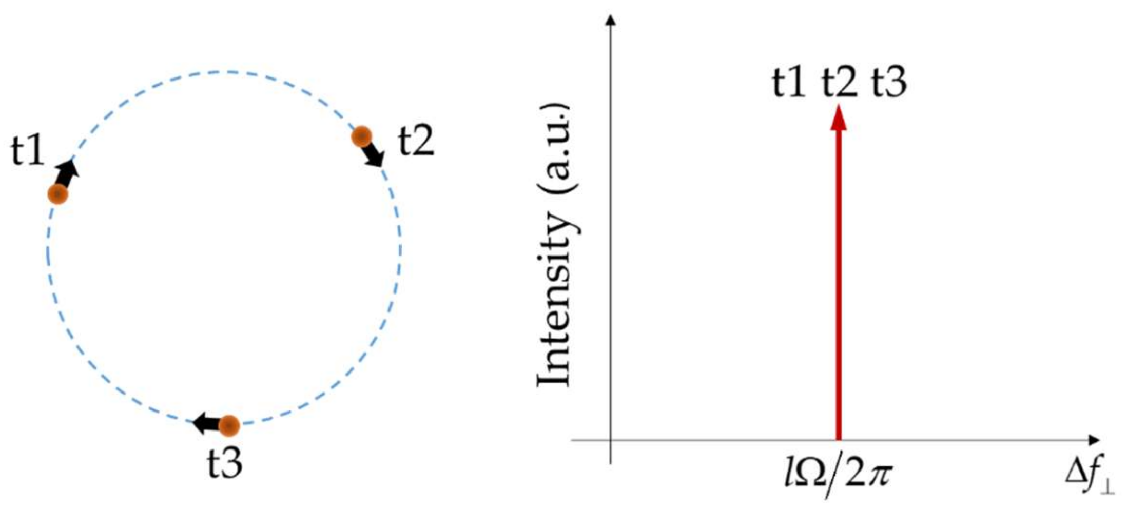
In 2011, Belmonte, et al. proposed a new method to directly measure the lateral velocity component of particles [
20] using structured light as an illumination source [
21]. In this scheme, the illumination beam in a fixed direction is wide enough in the transverse plane to cover all possible moving particles, and spatial phase profiles are tailored to adapt to the motion of targets. A new lateral Doppler shift related to the motion of the scatterer in the plane perpendicular to the beam axis can be expressed as
where the vectors on the right side are the transverse gradient of the spatially varying beam phase and the transverse velocity of the moving particle, respectively. As shown in
Figure 2, when the particle has a circular uniform motion around the beam axis, the spectral content of the returned signal from the scatterer is characterized by a single spectral line with a difference of ∆
f =
lΩ/2
π from the original frequency, where Ω is the instantaneous angular velocity of the scatterer. The distinct frequency shift makes it easy to identify the angular velocity, which can simplify the process of measuring rotational motion.
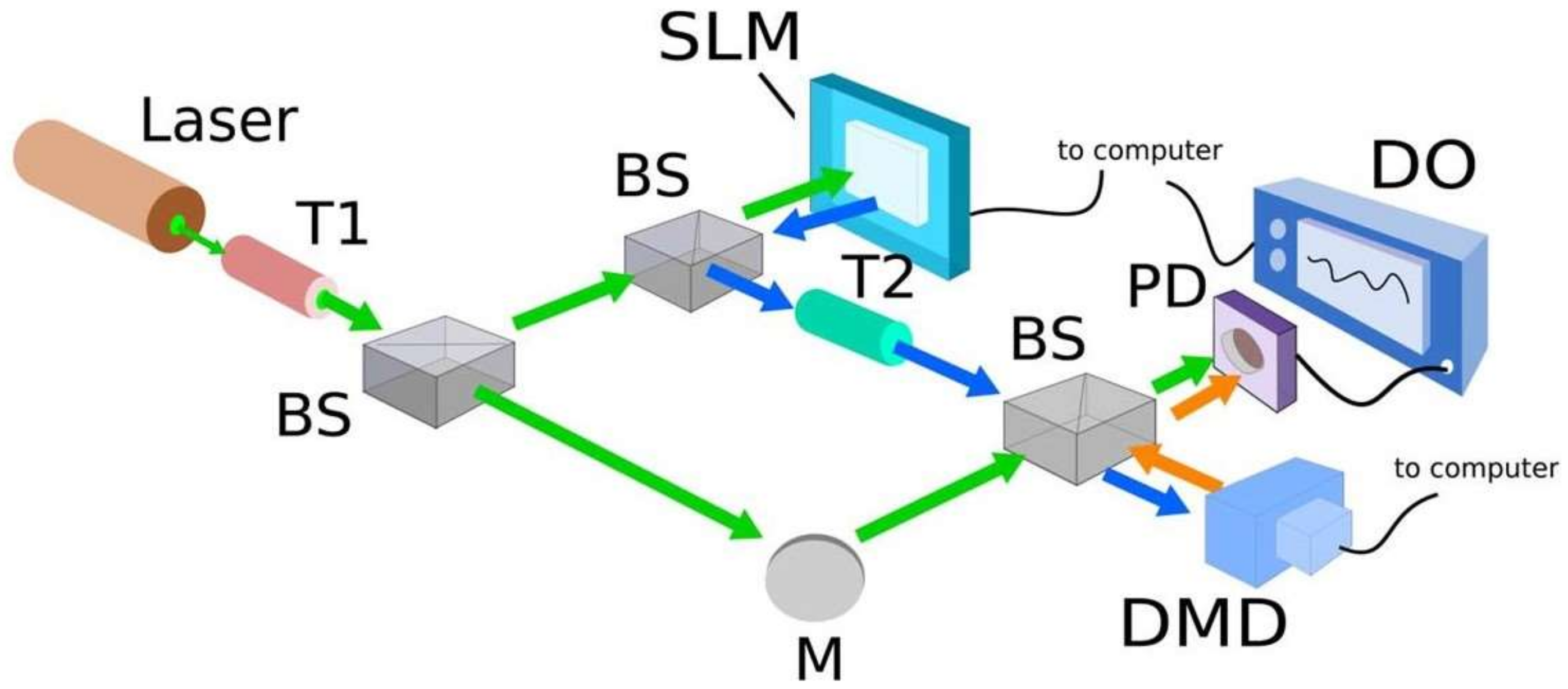
In order to verify the above method, in 2013, Belmonte, et al. used a digital micromirror device (DMD) to simulate the transverse motion of particles along a circular trajectory [
21]. The simulated moving particles are illuminated by a vortex beam and the scattered light is collected on a photoelectric detector (PD). By constructing an experimental system as shown in
Figure 3, the original beam is divided into two beams through the beam splitter (BS). One beam is used as the reference light, and the other beam carries the special phase distribution after being reflected from the spatial light modulator (SLM) as the detection light. The scattered light will carry the additional phase information related to the particle motion and, thus, its frequency will change when it reaches the detector, while the frequency of the reference beam is unchanged. When these two beams reach the PD simultaneously, a beat signal will be generated due to their different frequencies. Finally, after being filtered and processed to remove noise and unwanted signals with a digital oscilloscope, the beat signal can be obtained and its spectrum can be analyzed, as shown in
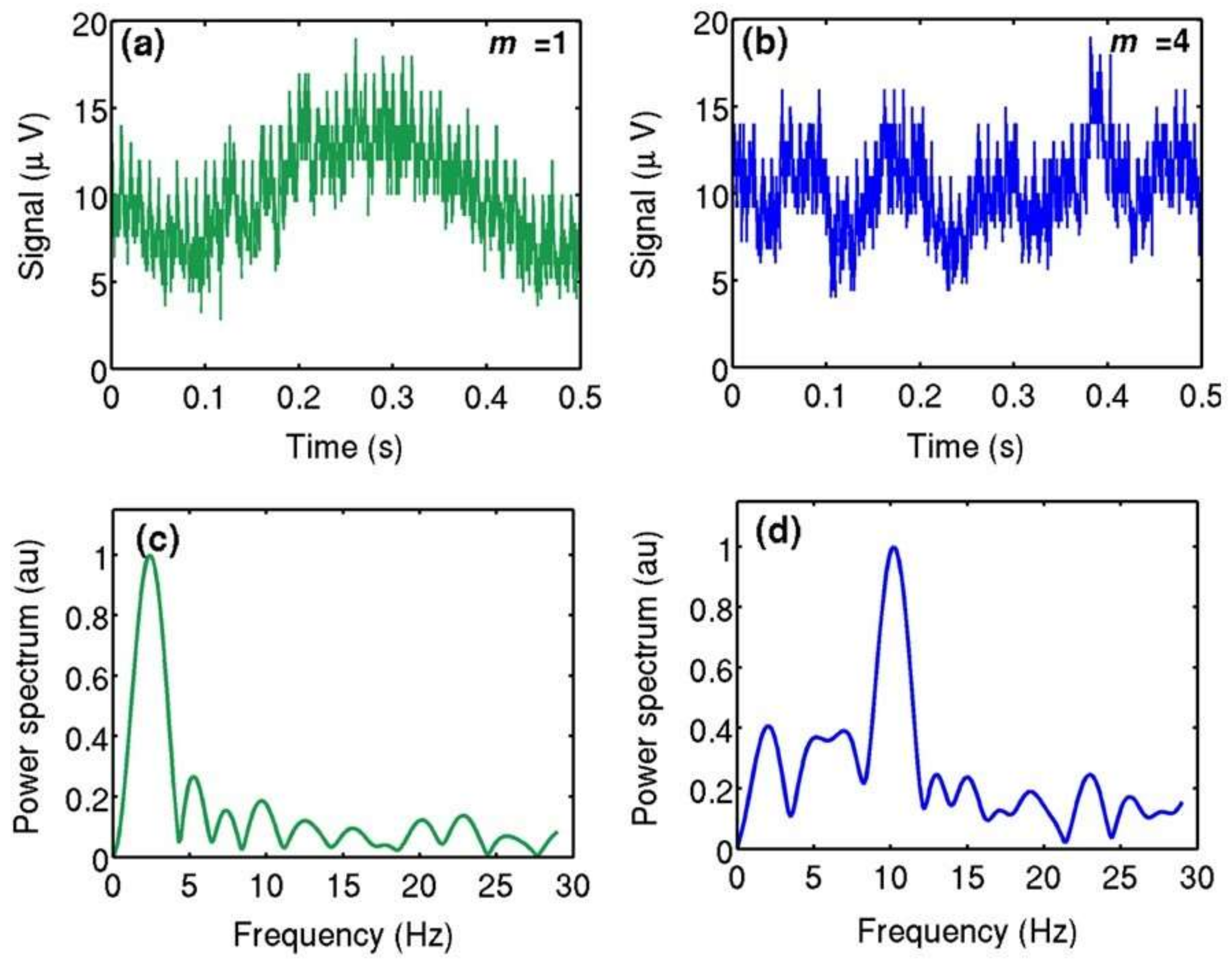
Figure 4. A specific peak can be observed in the frequency domain, which indicates the Doppler frequency shift associated with the velocity of the scatterer.
In 2014, C. Rosales-Guzmán, et al. demonstrated a method to determine the rotational direction of particles [
22]. Based on dynamically controlling the wavefront helicity of a vortex beam, the direction of a particles’ motion can be determined by comparing the frequency shifts of scattered light in two situations: with and without the probing beam rotation. When the phase of the vortex beam with topological charge
l is stable, the frequency shift of the scattered light is ∆
f =
lΩ
t/2π, where particle Ω
t denotes the angular velocity of particle. When the beam phase rotates with an angular velocity of Ω
s, the frequency shift becomes
It can be seen from Equation (3) that when the rotation direction particle is the same as the rotation direction of the vortex beam, the signs of Ωt and Ωs are the same, so |Δf′| < |Δf|. At this time, the frequency shift will be reduced compared with the situation when the beam phase is stable. On the contrary, when the target rotates in the opposite direction to the beam, Ωt and Ωs have opposite signs, and a higher frequency shift will be detected.
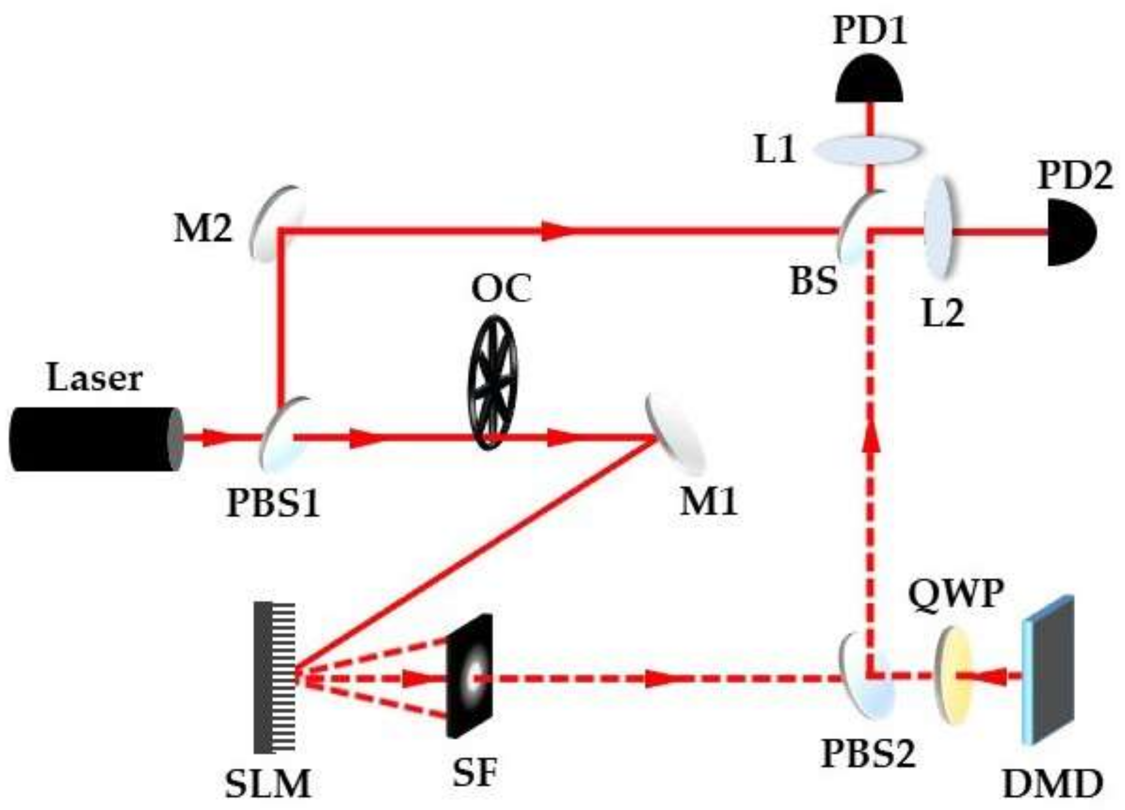
As shown in
Figure 5, a He-Ne laser beam is divided into a signal beam and reference beam using a polarization beam splitter (PBS) after collimation and beam expansion. The signal beam converts the frequency to the high frequency domain through an optical chopper (OC) to suppress the low-frequency noise, and then illuminates the SLM after the mirror M1. The first-order diffracted beam with a spiral wavefront is selected by the spatial filter (SF) and illuminates the DMD. Changing the hologram loaded on SLM with time induces the rotation of the generated vortex beam. The scattered light interferes with the reference signal through a beam splitter (BS), and balance detection is implemented using PD1 and PD2. First set the rotational velocity of the beam to 0 to obtain the rotation speed of the particle, and then observe the beat spectrum as the beam is rotated in opposite directions. It can be found that when the rotation direction of the beam is the same as that of the particles, the frequency shift decreases. On the contrary, when the rotational directions of the beam and target are opposite, the frequency shift increases, which is consistent with the theoretical analysis. Although this method can effectively detect the rotation speed and direction, at least two measurements are required, which may limit applications in real-time monitoring.
In 2021, Z.M. Li, et al. demonstrated a single sampling method to determine the direction, as well as the angular velocity, of a spinning object using a dual-frequency vortex light [
23]. When a dual-frequency (
f1 and
f2) 2-fold multiplexed vortex light is used to illuminate a rotating object, the frequency of intensity modulation can be expressed as
where
fref = |
f1 −
2| and
fD =
lΩ/π is the frequency of beat signal induced by RDE. Since the phase of a dual frequency 2-fold multiplexed optical vortex is time-varying, it will lead to continuous rotation of light, and the corresponding angular velocity can be expressed as ω = 2π(
f1 −
f2)/2
l. When
f1 >
f2, ω is a positive value, which leads to an anti-clockwise rotation of the superposed beam. If
f1 <
f2, the superposed beam will rotate clockwise. The relative velocity of a rotating beam and object will decrease when their rotation direction is the same, and the frequency difference between two vortex beams is reduced, leading to
fmod <
fref. When the rotational direction of a superposed beam is opposite to the object, their relative velocity is the sum of their velocities. Therefore, the frequency difference between the two vortex beams increases, and
fmod >
fref. By comparing the value of
fmod with the pre-set
fref, the rotation direction and angular velocity of the object can be determined using only a single measurement. Moreover, this method can automatically transfer the beat signal to the high-frequency domain and eliminate low-frequency disturbance, which is of great significance to obtain the precise rotation angular velocity.
In the above experiments, the researchers mainly focused on the detection of two-dimensional (2-D) transverse motion [
24,
25,
26]; however, the detection technology based on RDE has the potential to achieve three-dimensional (3-D) motion detection. In 2014, C.R. Guzmán, et al. measured the rotational and longitudinally translational velocity components of spirally moving particles under vortex beam illumination [
27]. The used experimental setup was similar with that shown in
Figure 5, and an additional translation stage was integrated with the DMD to simulate the longitudinal motion.
Spiral motion is the combination of longitudinal translation along the line of sight and rotation in the transverse plane. The longitudinal velocity component is determined by Gaussian beam illumination, while the angular velocity of rotational motion can be obtained when using a vortex beam as a probe. Besides the frequency shift caused by longitudinal motion, an additional frequency offset proportional to the rotation speed in the transverse plane can be obtained when the particle moves along a spiral trajectory, which can be expressed as
where
vz is the velocity of the target along the line of sight,
k = 2π/λ is the wave vector, and
λ is the wavelength of light. By measuring the frequency shift corresponding to the longitudinal and rotational motion, respectively, the full velocity of particles in spiral motion can be evaluated. This technology needs to select the appropriate spatial mode of structured light, which depends on the specific type of motion. By properly selecting the transverse phase profile of the illumination beam, this technology can be extended to the detection of microorganisms with a complete 3D movement.
Optical methods are widely used to measure vorticity in a flow, including particle image velocimetry (PIV) [
28,
29] and laser Doppler velocimetry (LDV) [
30,
31]. However, the accuracy of these methods needs to be improved [
8]. In 2015, Belmonte, et al. proposed a new optical sensing technology that can realize the accurate measurement of the local vorticity of a fluid without relying on the finite difference method or using probe particles [
8]. When the scatterer flows through the annular illumination area of OV, the vorticity information can be obtained from the transverse Doppler shift [
19,
20,
31] in the reflected signal, so as to realize the accurate measurement of vorticity.
In 2014, D.B. Phillips, et al. measured the angular velocity of one-micron sized particles in an optical trap using fringe interferometry [
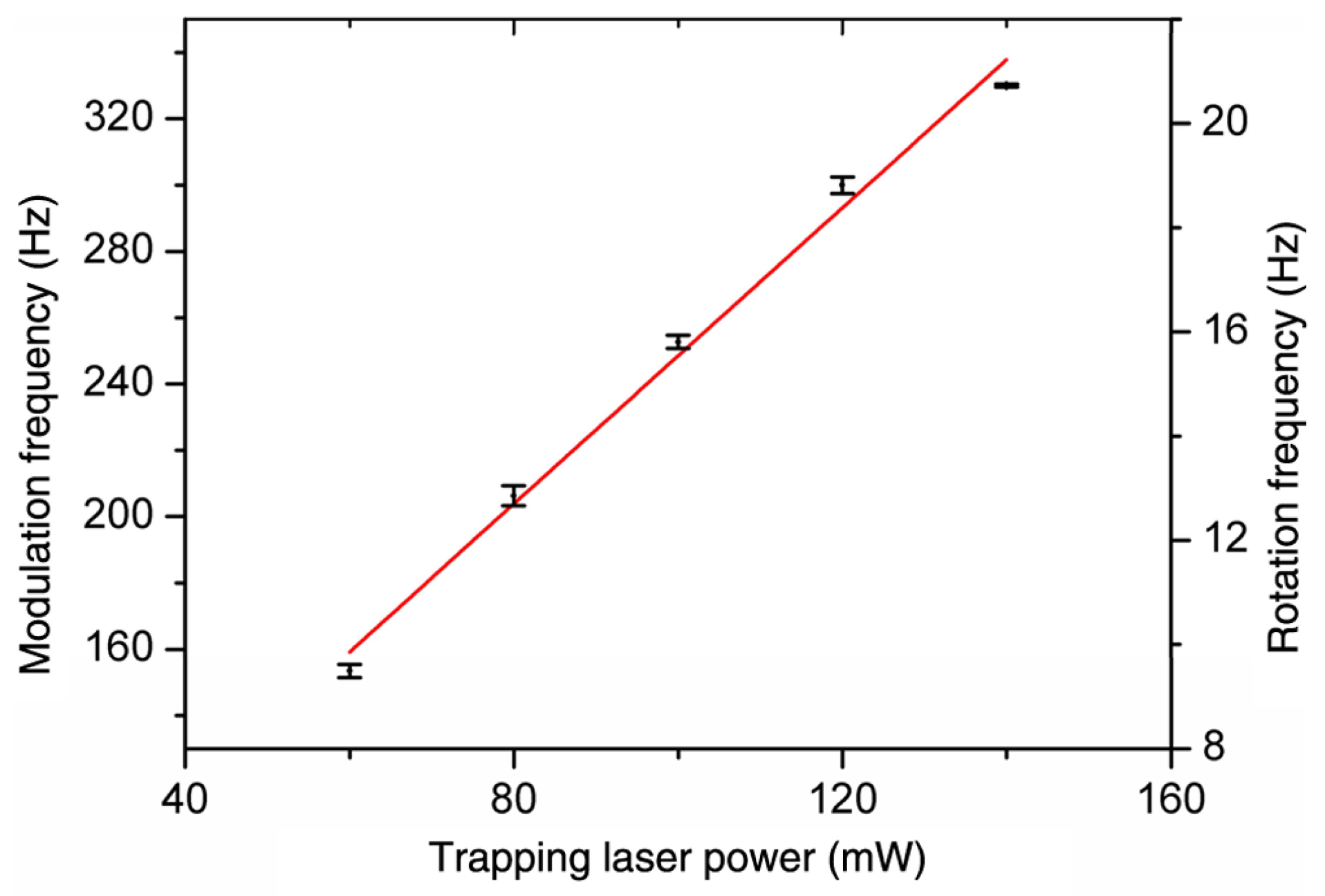
32]. This was the first report to combine RDE with an optical trap. The advantage of this detection method based on RDE is that the chirality, transparency, and birefringence of particles do not influence the measured results. However, the measurement accuracy is limited by the unstable speed and particle Brownian motion. In order to further improve the measurement accuracy of the rotational angular velocity of trapped particles, in 2018, X.L. Chen, et al. illuminated trapped hexagonal lead-acid microspheres with a superposed beam, consisting of vortex beams with opposite topological charge [
33]. By analyzing the spectral characteristics of scattered light, it can be observed that the frequency shift has a relation with the rotation rate of hexagonal soil microspheres, as
fmod = 2
lΩ. They proposed that the measurement accuracy could be further improved if the topological charge
l was increased, as shown in
Figure 6. When the topological charge becomes larger, the illumination area of the incident beam also increases, which can more widely include the roughness of the particle surface. Thus, a narrower width of spectral peak can be obtained in the beat spectrum, which means the accurate value of the modulation frequency is easier to locate. As shown in
Figure 7, when the trapping power is changed, the results are still in good agreement with the theoretical values. Therefore, it is more beneficial to analyze the spectrum characteristics of scattered light by illuminating trapped particles with superposed vortex beams with large and mutually opposite topological charges. This method is promising for detecting the torsional characteristics of a micro object.
4. RDE for Detecting the Rotation of Macro Targets
In the classical double-path methods for achieving rotation detection based on RDE, where the superposition of the scattering of the probe vortex beam and the fundamental Gaussian mode reference is constructed, the biggest problem is that the scattered light must be filtered and only the fundamental mode in the scattered light is used, which will greatly limit the detection efficiency for practical measurement. The all-optical detection method proposed by I.V. Basistiy, et al. uses superposed modals with different vortex topological charges as illumination and directly collects all of the rotating beam to form the beat signal in the signal-path detection [
17]. This method is instructive for solving the problem of the inefficiency in the double-path method and beneficial for achieving the angular velocity measurement of a practical macro rotating surface. At the macro level, the research on detecting the rotational angular velocity of practical objects, based on RDE, is also in full swing.
In 2013, M. Lavery, et al. detected the speed of a practical rotating surface based on RDE for the first time [
34]. According to the longitudinal Doppler frequency shift formula, the rotating Doppler frequency shift formula is
where
α = l/kr = lλ/2πr is the angle between the Poynting vector and the propagation axis of light [
35],
l is the topological charge number corresponding to the OAM of each photon
lh, and
k is the wave number; while,
λ is the wavelength and
r is the beam radius.
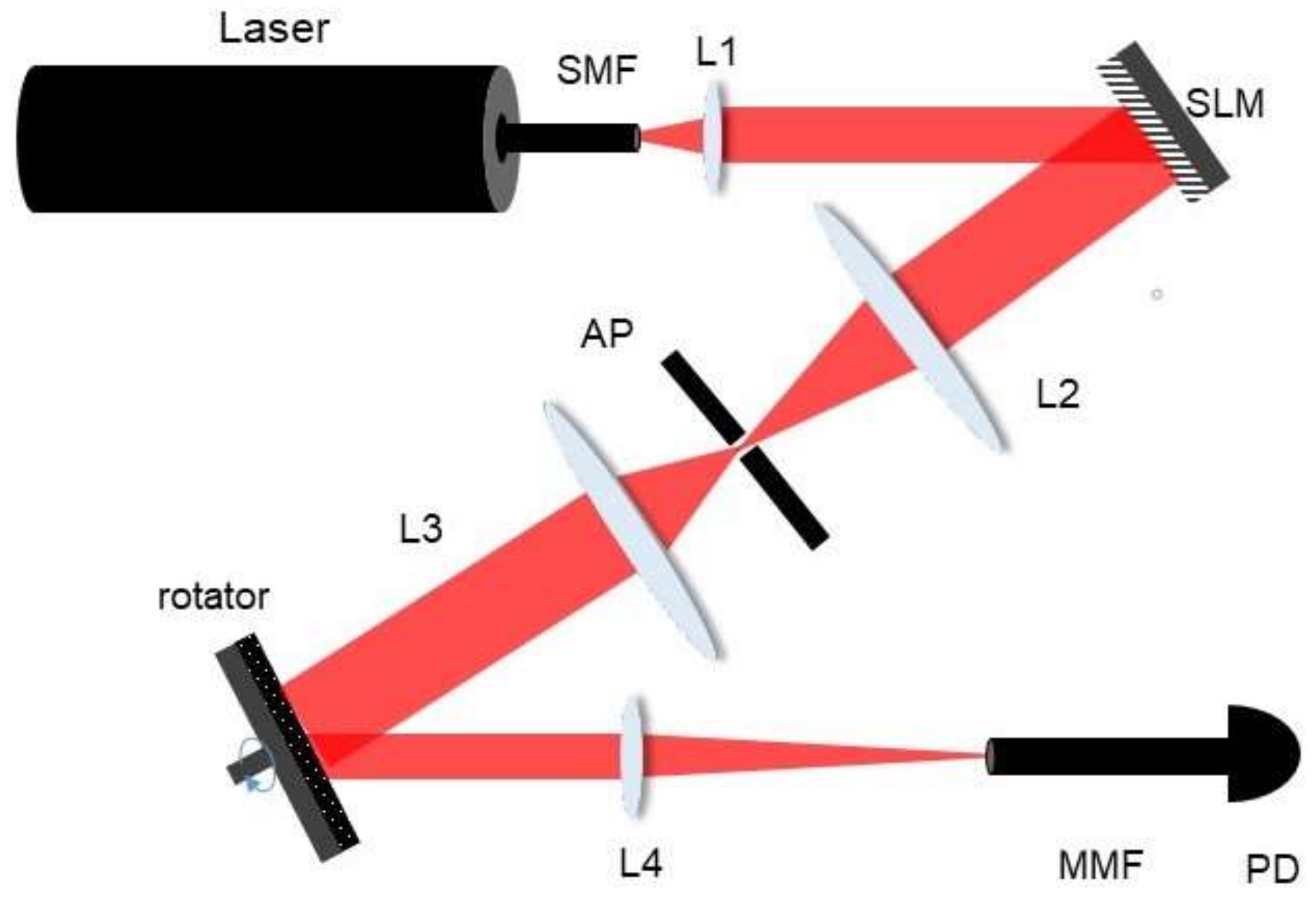
The experimental setup is shown in
Figure 8, the He-Ne laser beam is coupled into a single-mode fiber (SMF) and illuminates the SLM. The first-order diffracted beam is selected by the aperture (AP) and reimaged onto the center of the rotating rough surface. The scattered light is focused by a lens and collected by the PD. The illumination light consists of two helical phased beams with opposite vortex topological charges. As the rotating surface is rough, the scattered light from the rotating surface will theoretically contain all the vortex modes, regardless of the incident modal. For a specific detection mode, these two vortex beams experience different rotational Doppler shifts; however, the difference of these two frequency shifts is fixed, which leads to a stable frequency of intensity modulation, as
From the results demonstrated by M. Lavery, et al., a distinct peak corresponding to the desired beat frequency can be observed, based on which the accurate rotation angular velocity can be inferred. In addition, based on further analysis of the frequency variation of intensity modulation with time, the angular acceleration of a non-uniform spinning target can also be determined [
36].
In 2014, M. Lavery, et al. demonstrated the achromatic property of RDE, which is different from the liner Doppler frequency shift [
37]. In other words, the rotational Doppler frequency shift is independent of the illumination frequency, and each spectral component of white light has the same shift value in frequency after being scattered from a rotating object. The magnitude of the frequency shift is directly proportional to the OAM of the light and rotation angular velocity. When the rotating surface is illuminated by a superposed white light vortex beam with opposite topological charges, an obvious peak can be found in the spectrum of the intensity modulation of scattered light. There are a series of additional peaks near the modulation frequency, which originate from the lateral offset or tilt illumination of vortex beams on the rotating surface. In addition, it was demonstrated that the instability of the angular velocity of the rotating surface and the error in measurement will also lead to the emergence of additional peaks. It was also found that the rotation angular velocity of the object has a good linear relationship with the beat frequency when changing the topological charge of white vortex light, which is suitable for the remote sensing of rotating objects in astronomy [
38] and terrestrial applications, and has been applied for these purposes. Furthermore, in this work, M. Lavery, et al. put forward the idea of OAM mode decomposition, to explain and calculate the rotational Doppler frequency shift.
Over the years, the mechanism of RDE has been discussed from different aspects [
14,
17,
27,
37,
39]. In 2004, A.Y. Bekshaev, et al. demonstrated that the rotating optical image can be decomposed into a series of LG modes, and the frequency shift of the LG components caused by the RDE can be effectively observed in the beat spectrum, which is related to the rotating angular velocity of the beam [
40,
41,
42]. Similarly, in 2016, H.L. Zhou, et al. proposed and verified a theoretical model to fully explain the RDE on the rotating rough surface based on a modal decomposition method [
43]. The influence of a rough surface on the content of different frequency shifts, as well as the relationship between incident light, scattered light, and the object surface, were clarified [
44]. It was found that the frequency shift content is only determined by the surface, which has a linear relationship with the changed modal index between incident light and scattered light as follows:
where
l is the mode index of the incident light, while
m is the azimuthal index of the scattered mode reflected from the rough surface rotating at a fixed speed Ω. As shown in
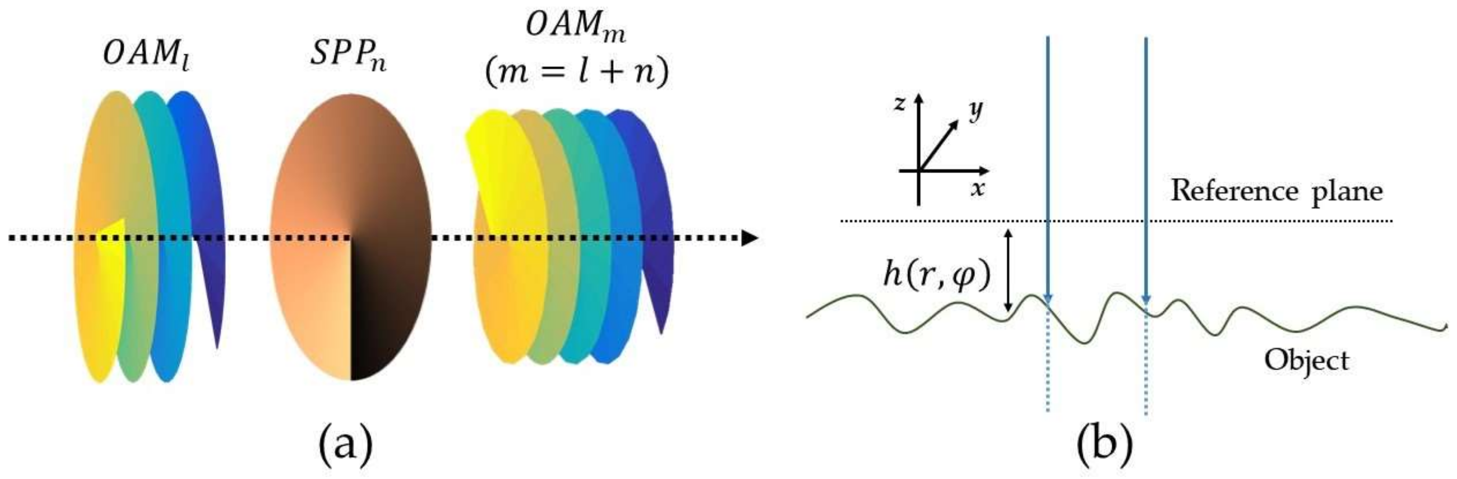
Figure 9a, the mode conversion can be realized by an ideal spiral phase plate (SPP), which can conduct a special phase modulation as
einφ [
43,
45,
46]. Assuming that the reflectivity of the spinning object is homogeneous, the rotating object can be regarded as a series of vortex phase modulators that only depend on the surface roughness. The roughness of stationary surface, as shown in
Figure 9b, can be written as
h(r,φ), and the modulated phase is given by Φ(
r,φ) = 4π
h(r,φ)/
λ. The modulation function in Fourier expansion form is as follows [
25]:
where
An(r) is the complex amplitude of
n-order harmonic,
n is the integer, and ∑|A
n(
r)|
2 = 1. When an incident vortex beam at frequency
f expressed by
B(
r)exp(−
i2πft)exp(
ilφ) is normally incident on the spinning object, the scattered light can be expressed as
It can be seen that the scattered mode with
m = n + l corresponds to a frequency shift of Δ
f =
nΩ, which is only determined by the surface of the rotating object and does not depend on the incident mode. The incident light only determines the mode content of scattered light, so the rotational Doppler frequency shift will also occur when the topological charge of the incident light equals 0 [
33]; as shown in
Figure 10, the power of the beating signal is directly proportional to the weight of the
n-order harmonic component of the spinning object, which is consistent with the results of the theoretical model. The theoretical model is helpful to better understand the physical process of RDE. By optimizing the modal properties of incident light, better RDE performance can be obtained.
Beyond the classical 2D detection of rotational motion, X.B. Hu, et al. demonstrated a technique based on an RDE of a vector optical beam to measure the 3D motion of a practical rough surface in a single measurement [
47], differently from the previous method that measures longitudinal and angular speed individually [
27]. The vector beam can be regarded as a superposition of orthogonally circularly polarized beams with different distributions of complex amplitude. A Gaussian beam with left-hand circular polarization is used to measure the longitudinal velocity of a moving object, while the petal beam with the right-hand circular polarization generated by the superposition of a vortex beam with opposite topological charges is used to measure the angular velocity of the moving object. Since two orthogonal polarizations are used, the information stored in each polarization can be clearly separated during detection, but collected simultaneously by the PD. The vector optical beam can be expressed as
where
and
represent the unit vectors of the circular polarization, and the coefficients
A = cos
β and
B = sin
β (
β ∈ [0, π/2]) enable a continuous variation, from a fully scalar beam (
β = 0, π/2) to a fully vector beam (
β = π/4). The Doppler shift of this vector beam after scattering from a 3D moving object can be expressed as
The superposed vortex beam can directly form a beat signal after scattering from a rotating object without reference light, while the Gaussian beam can provide information about the longitudinal velocity component after the interference with a left-hand circularly polarized reference beam.
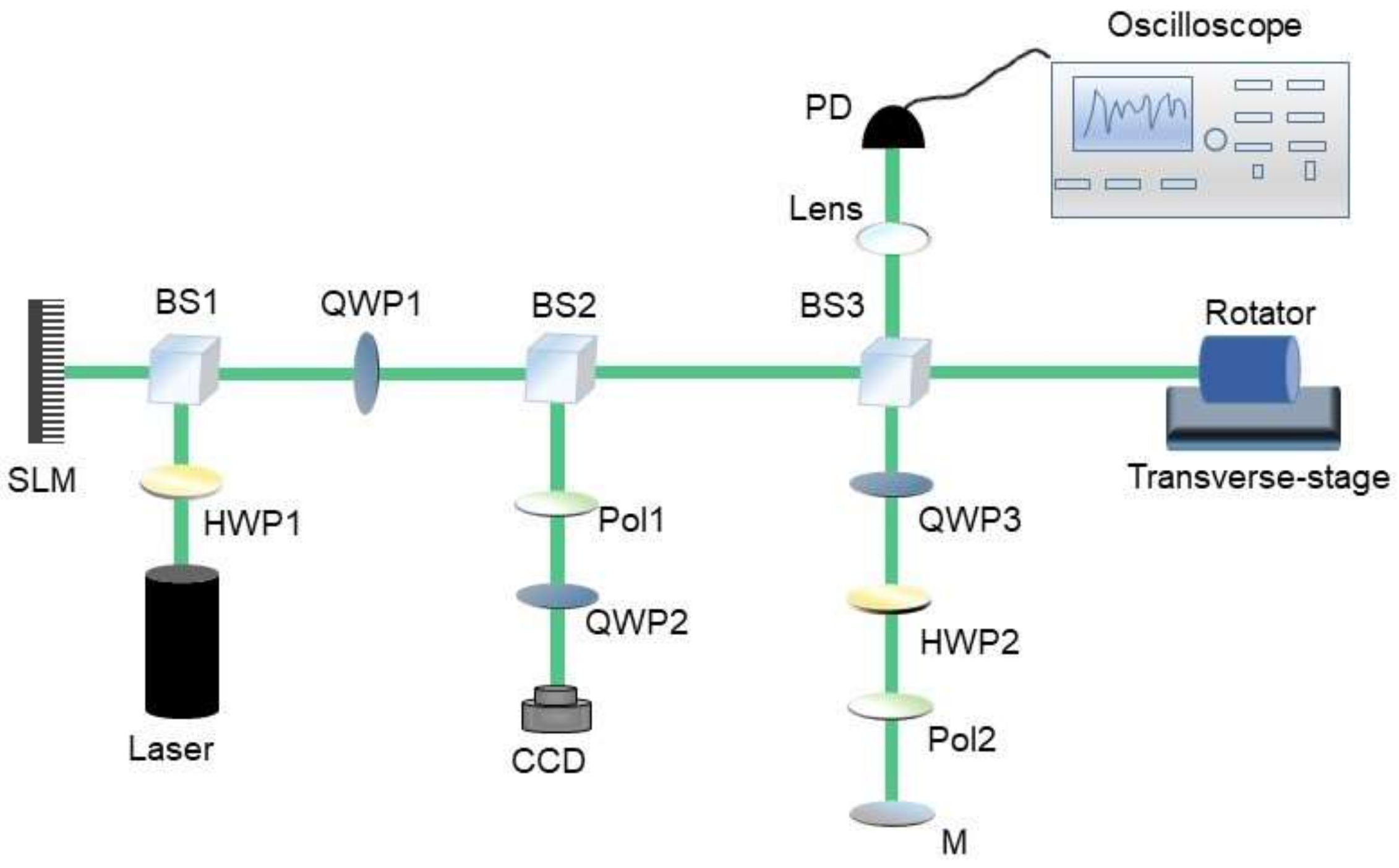
A diagram of the experimental set-up is shown in
Figure 11. According to the polarization sensitivity of SLM, the horizontally polarized beam is modulated as a petal-like structure, while the vertically polarized light remains a Gaussian beam. The linear polarizations are converted into circular polarizations by a 45° QWP, and the desired vector optical beam is generated. After passing through the BS3, the vector beam is divided into a reference beam and a detection beam. The beam containing the vortex light structure in the detection beam does not need a reference light to obtain the rotational Doppler frequency shift, and the angular velocity can be inferred based on the generated beat signal. After passing through 45° QWP, 45° HWP, and a horizontal LP, the right-hand polarized component in the vector optical beam is removed and the remaining light functions as a reference beam. The beat signal that is used to measure the longitudinal motion is generated from the interference right-hand polarized detection beam and reference beam. The detection signal is focused on the PD through a lens and connected to a digital oscilloscope to observe its spectrum characteristics.
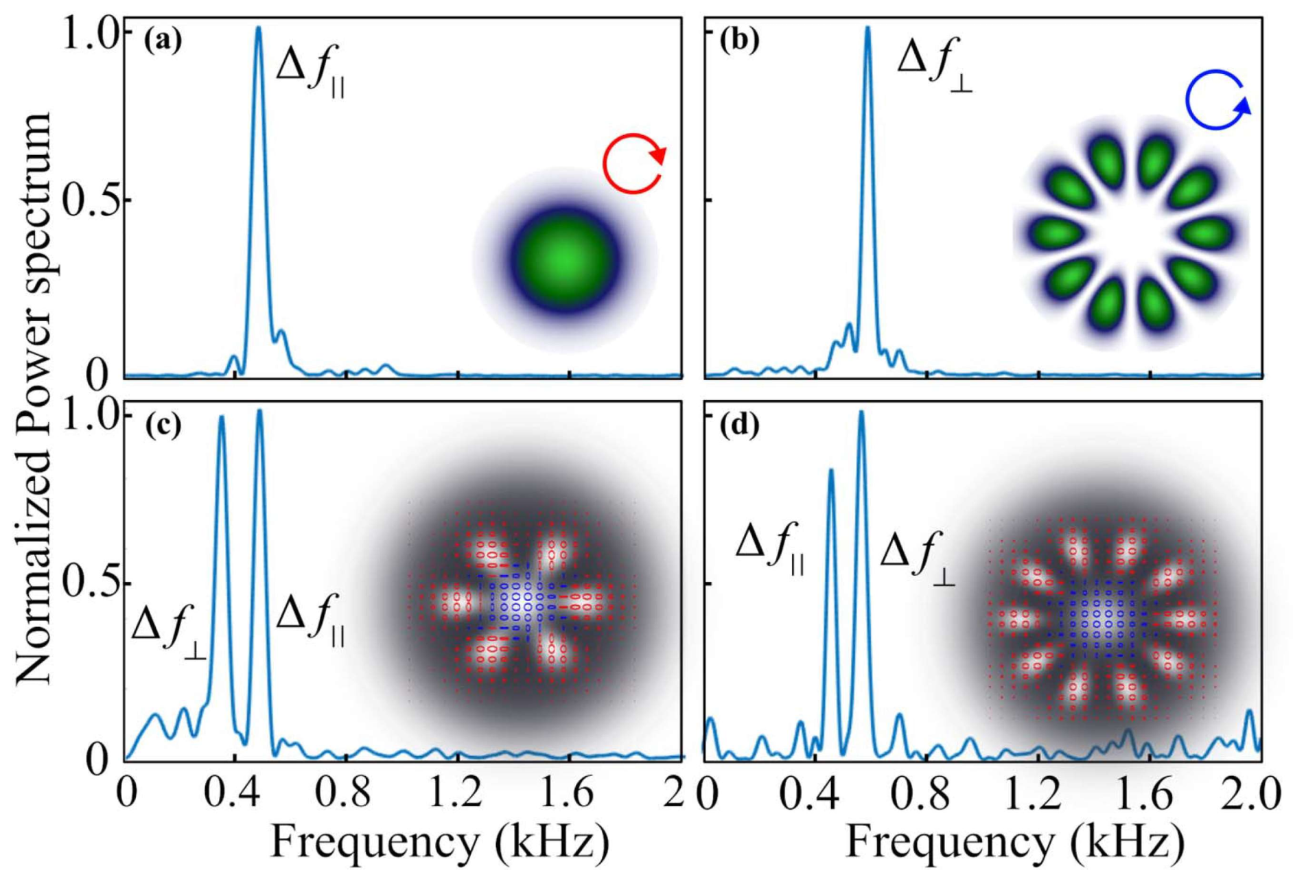
First, the intensity modulation spectrum corresponding to the situation of longitudinally moving objects illuminated by Gaussian light and rotating objects illuminated by superposed vortex beams was investigated. As shown in
Figure 12, a single peak in each case could be observed. The longitudinal velocity and rotational velocity of the moving object could be obtained by calculation. When the vector optical beam is used for illumination, it can be found that the peaks caused by the longitudinal and rotational motion coexist in the spectrum, which is consistent with Equation (12). When changing the topological charges of a superposed petal-like beam, the peak corresponding to the rotational motion will move, while the other peak will be stable. This phenomenon can be used to distinguish peaks caused by longitudinal and rotational motion. This method can be integrated into existing laser remote detection equipment, making it possible to manufacture equipment that can measure the longitudinal velocity and angular velocity of remote targets at the same time.
In 2018, W.H. Zhang, et al. demonstrated that the rotation speed, as well as the rotational symmetry, can be effectively detected over a 120-m-long free space based on the RDE of a vortex beam [
48]. This shows that, in addition to the dominant mode and frequency shift caused by RDE, adjacent modes in the scattered light, due to the influence of atmospheric turbulence and slight incident misalignment, may also appear when propagating over a large distance. By analyzing the frequency shift of the adjacent modes, the rotation speed and rotation symmetry of the object can still be determined. The scheme adopts a single photon counting module and can work under extremely weak illumination, which makes it possible for remote sensing in real environments. In 2020, Y.W. Zhai, et al. first detected the rotation angular velocity of a real rotating object within a small error range at a distance of tens of meters in an outdoor environment based on RDE [
49]. From the perspective of mode purity, they analyzed the influence of lateral misalignment of illumination on Doppler frequency shift, based on the modal expansion method. It is concluded that a longer detection range can reduce the influence of possible beam misalignment on detection. This scheme lays a good foundation for the measurement of angular velocity of remote rotating objects in outdoor environments.
5. RDE with Misaligned Illumination of a Vortex Beam
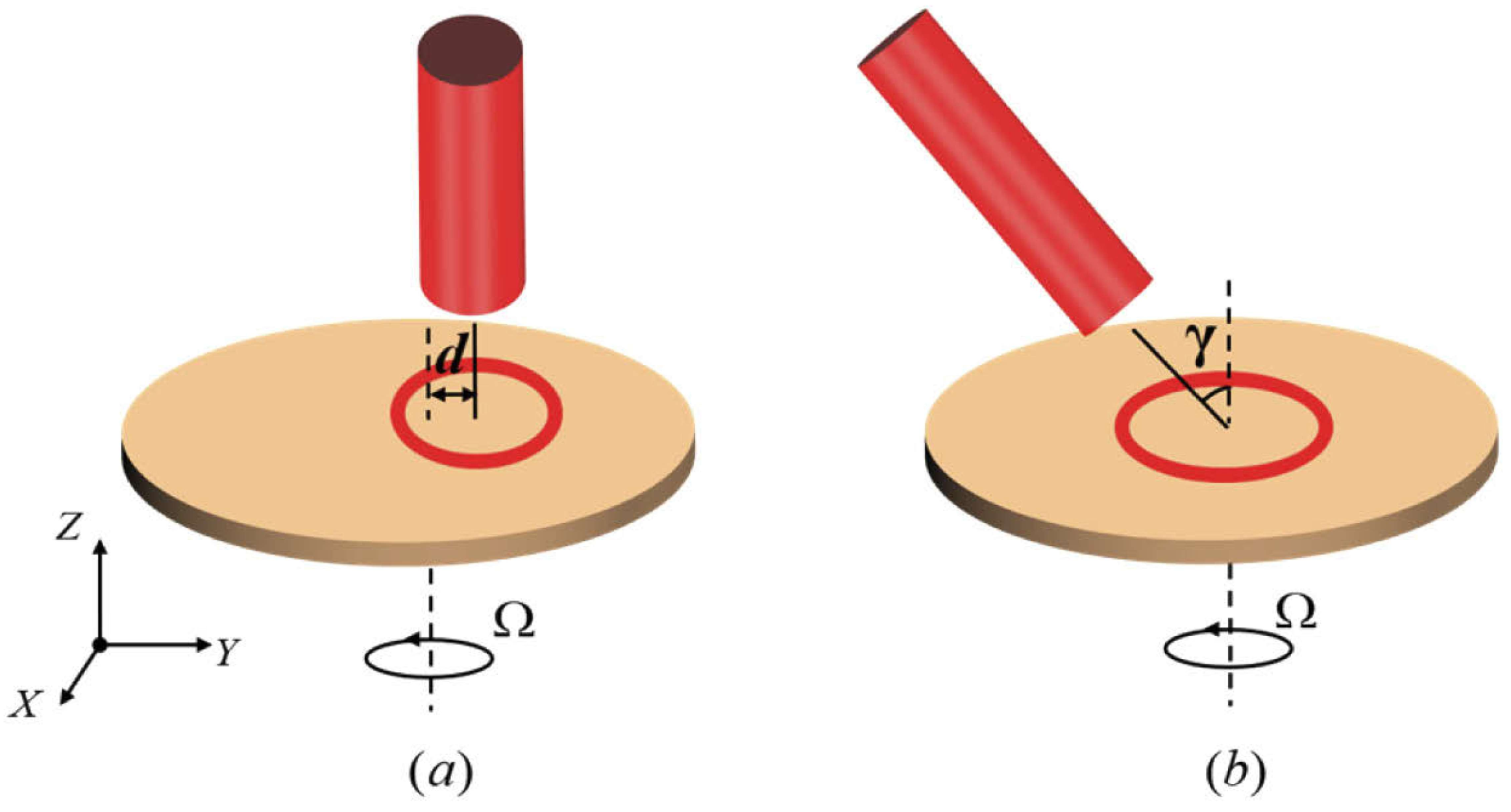
Most of the above investigations were based on the condition that the axis of a vortex beam coincides with the rotation axis of the object. In practical applications, it is still possible for the beam to accurately hit the center of the rotating surface in short-range detection, but it is undoubtedly more difficult to make the beam accurately incident on the center of the micro particles, with a rotating surface with remote distance and complex structure. Therefore, the study of the RDE when the beam is misaligned with the rotation axis is of great significance for the practical application of RDE. The misalignment of an illuminating beam can be divided into two aspects: lateral misalignment, and tilt illumination.
In 2019, Q. Song, et al. considered the lateral misalignment of the normally incident beam and investigated the influence of the distance deviation between the beam axis and rotation axis on RDE [
50]. Based on the local scattering model, the rotational Doppler frequency shift in a misaligned situation is derived as
where
r1 is the radius of annular vortex beam,
r2 is the radius from the rotation axis to the point where the velocity is measured,
f0 is the original frequency of light, and
γ represents the angle between the actual velocity and its azimuthal projection in the polar coordinate with the beam center as the origin. When the superposed vortex beams with opposite topological charge
l are incident on the rotating surface, the scattered light will produce an opposite frequency shift, which leads to intensity modulation with the frequency
where
d is the distance between the rotation axis and the center of the optical vortex, and
θ is the azimuth of any point of the beam spot. According to Equation (14), when the beam incident on the rotating surface is laterally misaligned, the spectrum of beat signal will be widened proportionally to the amount of lateral misalignment
d.
They carried out an experiment with an experimental device similar to
Figure 8, and the results showed that when the lateral misalignment is introduced, the spectrum of beat signal experiences a certain broadening near the central frequency, as shown in
Figure 13, which is consistent with the prediction of Equation (14). The width of the frequency peak depends on the magnitude of the lateral misalignment, and the frequency peak position is equal to the frequency of rotation [
51,
52]. With the increase of lateral misalignment, the spectral bandwidth increases and the amplitude decreases, which leads to a decrease of the signal-to-noise ratio.
The errors of theoretical center frequency and measured center frequency under different lateral misalignment states were also studied. They found that the theoretical value is basically consistent with the measured value, and the change of center frequency is quite small. In addition, the changes of spectral bandwidth have a linear relationship with the lateral misalignment d.
It is worth noting that only the small-scale lateral offset of the beam in the disk was considered; that is, the rotation center of the object is still in the beam spot. The change of the rotational Doppler shift caused by the large lateral misalignment is more crucial in remote detection applications. In 2020, Z.J. Zhang, et al. proposed a rotational angular velocity measurement method where the beam spot completely deviated from the rotation center, based on the theory of linear velocity decomposition [
53].
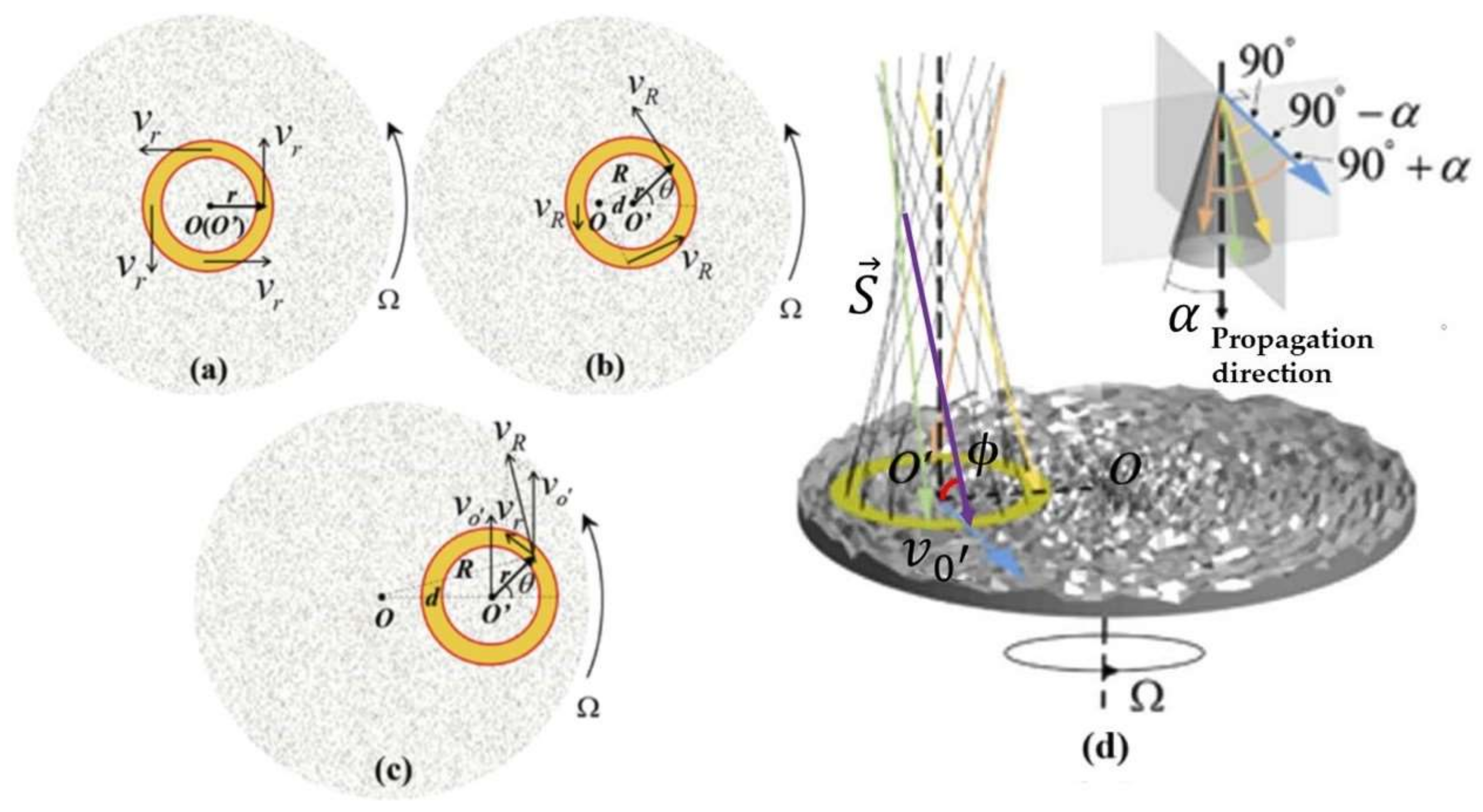
When there is no misalignment, as shown in
Figure 14a, the generated frequency shift is ∆
f =
lΩ/2
π. When the incident beam is offset from the rotation center, but the rotation center is still within the light spot, as shown in
Figure 14b, the generated frequency shift is
where
r is the radius from the beam axis,
d is the offset between the center of rotation (
O), and the center of the beam spot (
O′).
θ is the azimuthal coordinate of the beam
. It can be concluded that with the increase of lateral misalignment
d, the frequency shift ∆
f becomes dispersed. When there is a large misalignment, i.e.,
d > r, as shown in
Figure 14c, the linear velocity at an arbitrary point of the annular light spot can be decomposed into the transverse velocity component
v0′ (
v0′ =
dΩ) and the tangential velocity component
vr (
vr = Ω
r). Thus, the rotational motion at point
O can be regarded as a combination of the translational motion
v0′ and the rotational motion relative to point
O′. When the rotation center of the rotating surface is completely out of the beam spot, the frequency shift caused by the tangential velocity component
vr is
For spinning object detection, the frequency shift caused by the tangential velocity component
vr can be used to explore the rotational angular velocity of the object. The maximum frequency shift caused by the translational velocity component
v0′ is
As shown in
Figure 14d,
f0 is the original frequency of light and the
ϕ is the angle between the Poynting vector and the velocity vector. When
ϕ = 90°, the minimum frequency shift is ∆
fmin = 0. Thus, the range of frequency shift caused by
v0′ is [0, |∆
fmax|], which can be considered ground noise. When the misalignment
d increases, it will lead to the increase of
v0′, and thus ∆
fmax gradually increases.
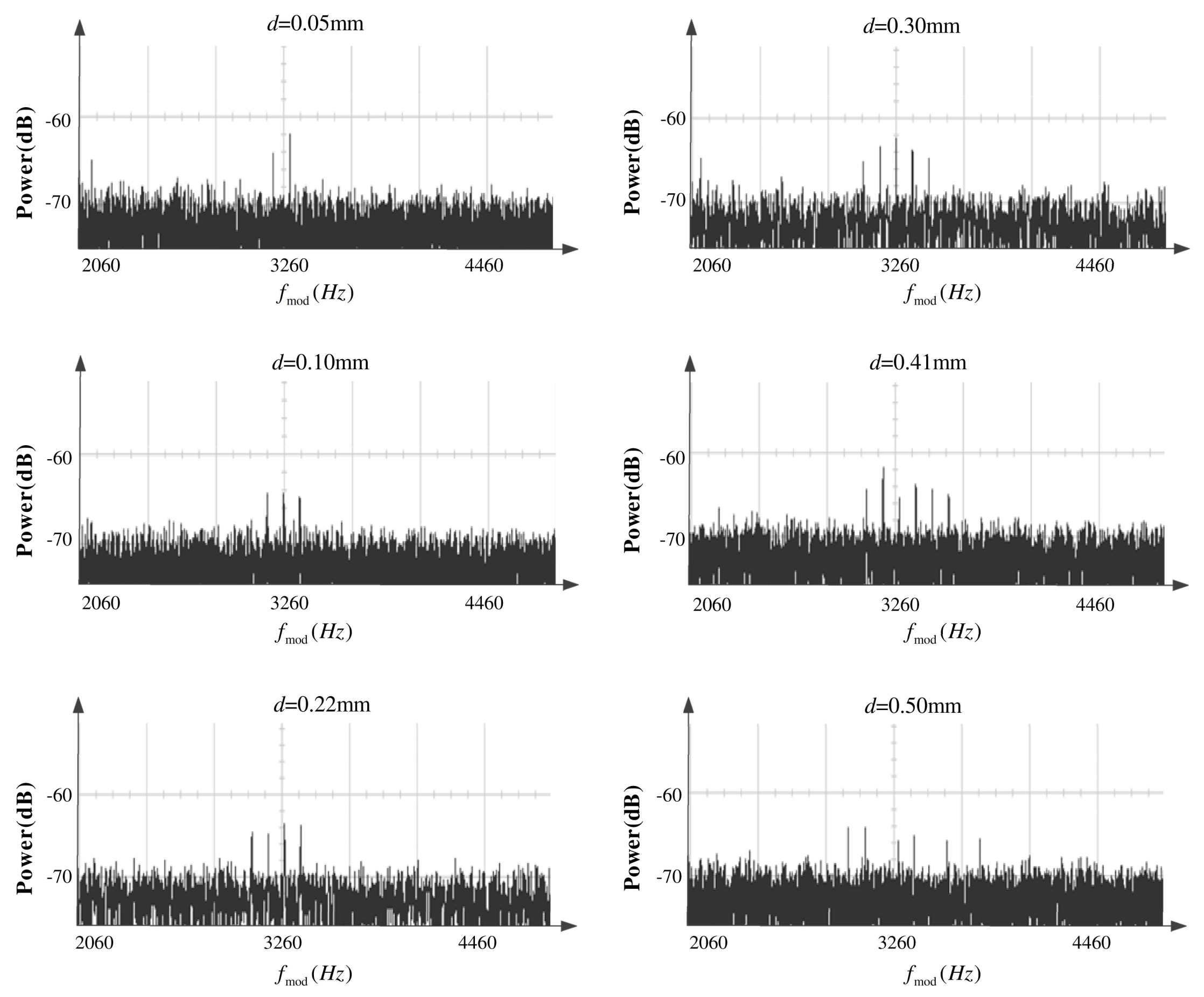
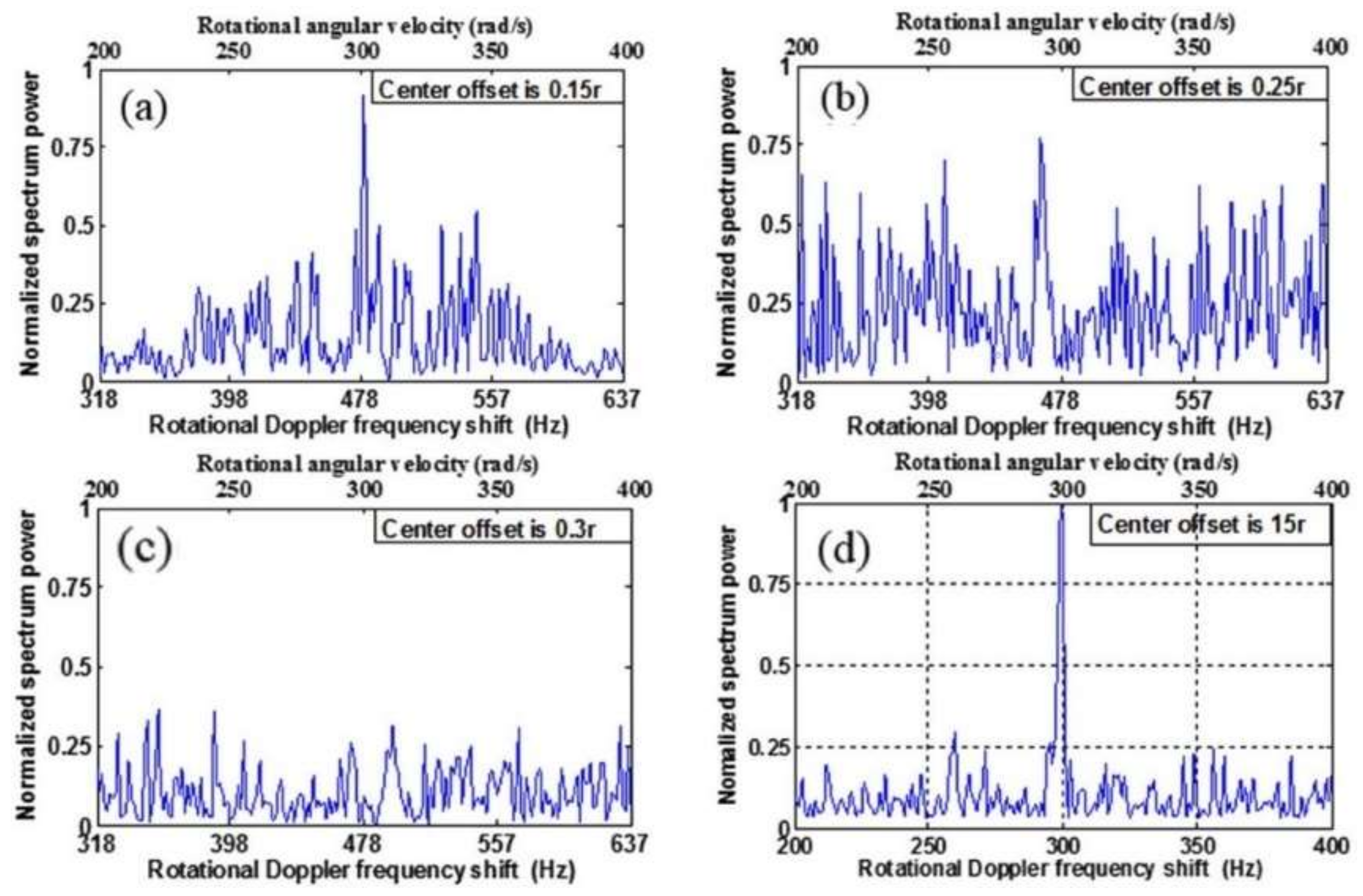
As shown in
Figure 15, when the lateral misalignment
d increases, the peak value of the beat signal gradually widens and weakens, which will increase the measurement error and decrease the signal-to-clutter ratio (SCR). When
d is greater than 0.25
r, the SCR declines sharply which leads to the proportion of the main peak of the signal gradually decreasing or even being completely lost. At this time, the measurement error increases sharply, and the system cannot work properly. When the rotation axis is far away from the light spot, the SCR increases and the main peak of the Doppler shift signal tends to be more obvious. This shows that when the beam is far away from the interference of the rotation center, the translational velocity feature caused by the lateral misalignment will be more obvious than the rotation feature. At this time, it is easy to locate the main peak and calculate an accurate rotation angular velocity.
Besides the lateral misalignment of the illumination, another key factor affecting rotational Doppler frequency shift is the incident angle of light. From the perspective of energy exchange, in 2004, A.Y. Bekshaev, et al. demonstrated that when the beam axis and the beam rotation axis have an angle, the frequency shift generated by the RDE will be proportional to the square of the cosine value of the angle between the beam axis and the torque direction applied to the beam [
41,
54]. As for the situation when the RDE happens with a rotating surface, in 2019, Q. Song, et al. researched RDE when a beam is incident obliquely, based on the local scattering model, and established a quantitative relationship between the Doppler frequency shift and the incident angle of the beam [
55]. Due to the oblique incidence of the beam, the circular beam profile illuminated on the rotating surface changes into an ellipse, as shown in
Figure 16.
When a superimposed vortex beam with opposite topological charge ±
l illuminates the surface of a rotating sample at a certain incident angle
γ, it will produce an opposite rotational Doppler shift and equal linear Doppler shift. Regarding the beat signal, the linear Doppler shift can be counteracted, and only the rotational Doppler shift contributes to the intensity modulation, whose frequency can be expressed as
The minimum and maximum beat frequency
fmin and
fmax are
lΩcos
γ/2π and
lΩ
/2πcos
γ, respectively. The center frequency
fc is
which is only determined by the topological charge
l and the rotational angular velocity Ω.
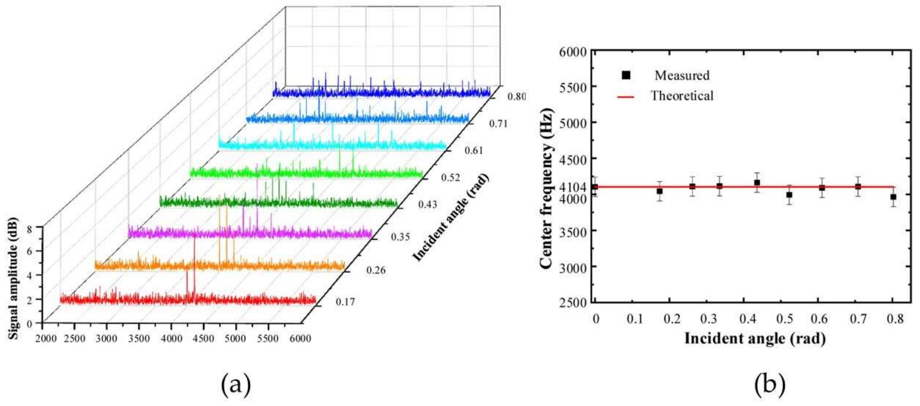
The experimental results are shown in
Figure 17a. When adjusting the turntable to make the beam incident on the rotating surface at a certain angle, the spectrum signal is no longer a single peak profile, and a certain number of adjacent peaks appear, which is consistent with the prediction in Equation (18). However, the center frequency
fc can still be calculated according to Equation (19), which can be used to calculate the rotational angular velocity of the object. When the incident angle exceeds 0.87 rad, all the peaks are too weak to be recognized. Therefore, an effective beat signal can only be obtained within a certain illumination angle. As shown in
Figure 17b, within the incidence angle range of 0.17–0.87 rad, the
fc corresponding to different incident angles is almost constant, and the error between the experimental and theoretical value is very small, which can ensure the accuracy of the measurement.
Since H.L. Zhou, et al. put forward a theoretical model of RDE based on the modal decomposition method in 2016 [
43], the modal decomposition method has been widely used to analyze the modal properties of the scattered light of rotating objects. In 2021, Y. Ding, et al. analyzed the influence of the lateral misalignment and incident angle of the beam on the rotational Doppler shift of a scattered light, based on the OAM mode decomposition method [
56]. It has been proven that when the beam is laterally misaligned or angular deflected, its modes will expand [
41], which will further influence the frequency shift spectrum of the beam after scattering from a rotating surface. The misaligned OV beam can be expressed as the superposition of a series of beams coaxial with the reference axis [
44]. A standard LG mode with OV propagating along the
z axis can be expressed as:
where
E0 denotes the amplitude coefficient,
w0 is the beam waist radius,
Lp|l| is the symbol of associated Laguerre polynomial,
l is the topological charge, and
p is the radial index. When a lateral displacement is considered, as shown in
Figure 18a, the optical axis is parallelly displaced by
d in the
y-axis. The laterally misaligned OV can be expressed as
where (
re
iφ−-
deiφ)
l contains the helical harmonic factor
eilφ. Using the same method to consider an angular deflection, as shown in
Figure 18b, the tilted OV can be expressed as
where
γ is the incident angle and (
rcos
φ +
irsin
φcos
γ)
lcontains the helical harmonic factor, which can be expanded as
It should be noted that the azimuth coefficient is 2n−-l, so the difference between adjacent modes of scattered light is 2, when the beam is incident obliquely. In other words, when the vortex beam illuminates the rotating surface with a certain lateral misalignment or incident angle, the mode of the incident light can be considered as the superposition of vortex beams with discrete topological charges, which is centered with rotational axis.
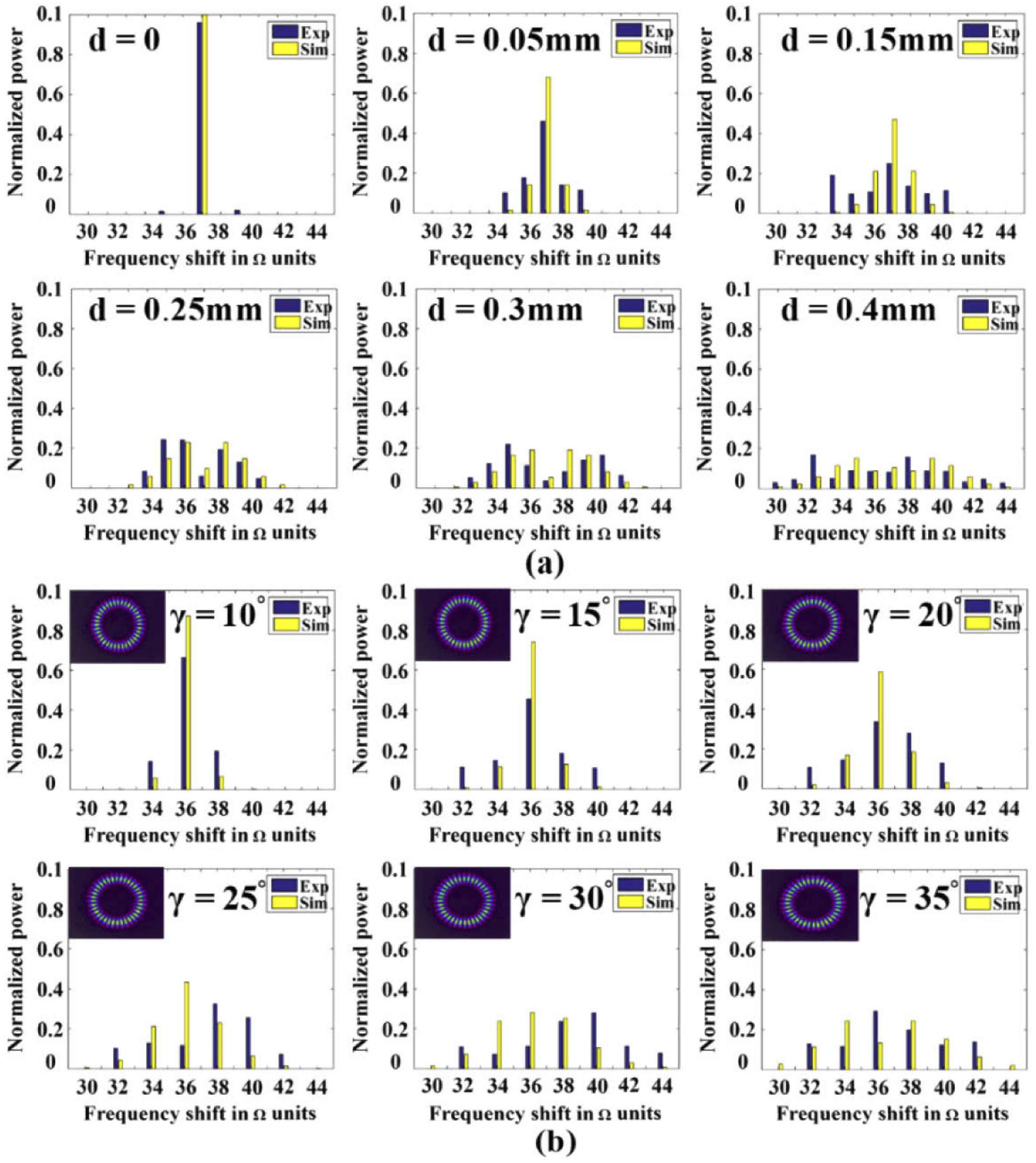
Compared with a coaxial incidence, the frequency shift spectrum of RDE when the beam is misaligned with the rotation axis becomes wider, due to the expansion of the incident vortex mode. At the same time, the power of the beat signal in the scattered light is proportional to the product of the intensity of the two superposed modes. As shown in
Figure 19a, it can be seen that, with the increase of lateral misalignment, the spectrum widens and the new peaks are symmetrical with the main peak. The interval between adjacent peaks is equal to the rotation angular velocity Ω of the rotating surface. Then the effect of the incident angle on the frequency shift can be considered. As shown in
Figure 19b, when the incident angle increases, the spectrum widens compared to the single main peak in the situation of a small incident angle, and the frequency interval between adjacent peaks is equal to twice the rotational angular velocity. The experimental results are consistent with the theoretical derivation. Therefore, two methods can be used to calculate the rotation angle velocity Ω when the beam is misaligned with the rotation axis: one is based on the method of modal decomposition to identify the peak and corresponding superposed modes, which can be further used to calculate the rotational angular velocity. Another way is to observe the frequency interval between adjacent peaks in the spectrum to calculate the rotation angle velocity. It can also be demonstrated that the discretized modal decomposition method improves the accuracy of calculating the rotational angular velocity of the object. On the one hand, the connection between
fmod and the scattered modes is more conducive to reducing the error. On the other hand, from the frequency interval of adjacent peaks, the range of angular velocity can also be determined within a certain error range.

 and
and 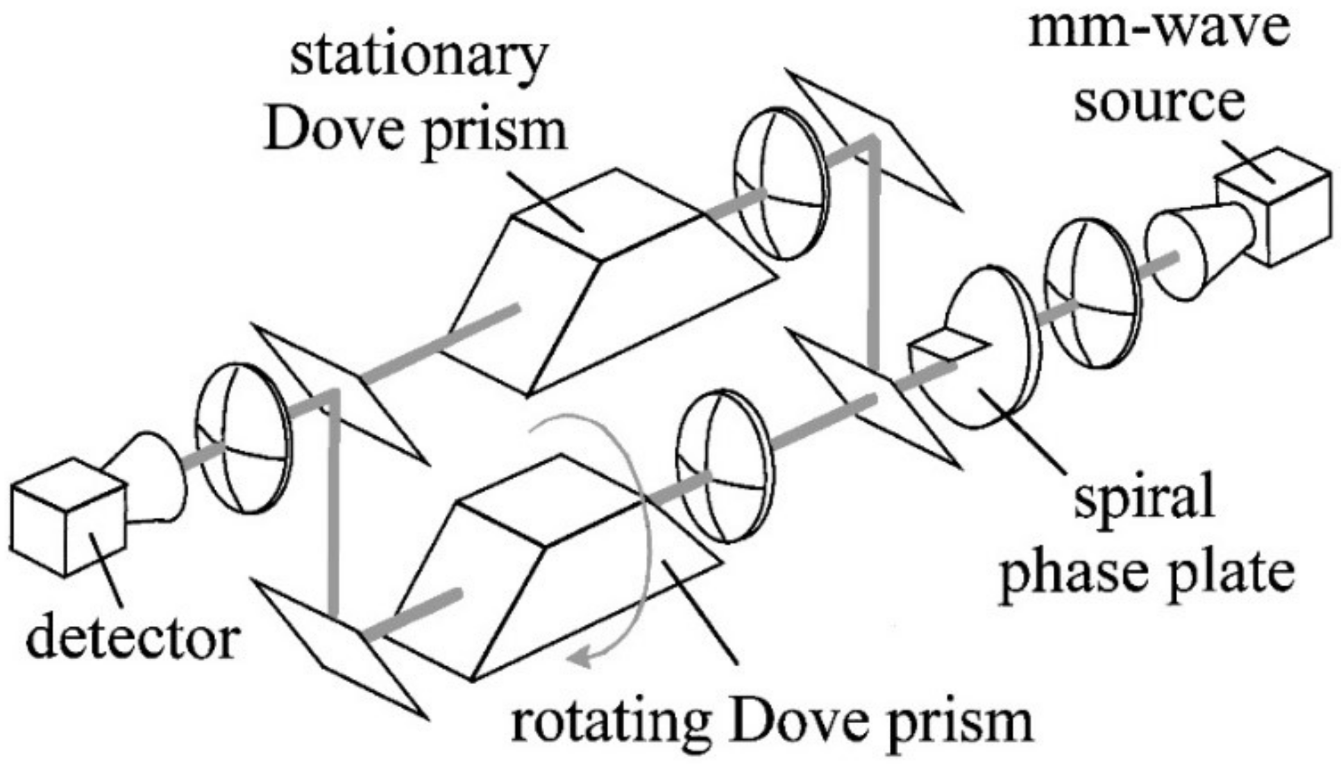


