Abstract
A microwave photonic converter based on microwave pre-upconversion is proposed and experimentally demonstrated. Only a single Mach–Zehnder modulator (MZM) is used in the converter system so that the complexity and bandwidth limiting of the link can be reduced. The transmitted and received signals before entering the MZM are firstly upconverted to high frequency (HF) by a microwave upconverter. The HF and local oscillator (LO) signals are combined to drive the MZM. Carrier-suppressed double-sideband (CS-DSB) modulation is introduced to the MZM for effective spectrum utilization. Then, the target signals can be obtained by photoelectric conversion and beating. Experimental results confirm that the mixing spurs including harmonics and intermodulation as well as original signals are all out of system frequency band from 0.8–18 GHz, and the in-band spurious suppression of at least 40 dBc is achieved. In addition, the spurious-free dynamic range (SFDR) reaches 86.23 dB·HZ2/3 for upconversion and 80.95 dB·HZ2/3 for downconversion. The proposed microwave photonic converter provides a wideband and high-purity alternative for the applications of radars and signal processing.
1. Introduction
Microwave converters, which are used to perform frequency conversion including upconversion and downconversion, are a fundamental part of transceivers and can be applied in many fields, such as satellite communication, radars, and microwave signal processing [1]. The upconversion has the process of increasing the intermediate frequency (IF) to the specified radio frequency (RF) point, and it is used to achieve high-gain launching and transmission. Meanwhile, the downconversion moves the spatial RF signal to a fixed IF point through conversion and filtering, which is convenient for the signal processing circuit to sample and analyze.
Conventionally, the technology of the microwave electrical converter is mature and has high conversion accuracy [2,3]. However, it suffers from low LO/RF isolation (15 dB) and high LO drive power (10 dBm) [4,5]. Furthermore, bandwidth limitation and large insertion loss also restrict the application of the electrical converter [6]. Over the past 30 years, microwave photonic technology [7] received extensive attention due to its advantages such as wide bandwidth and the immunity to electromagnetic interference. This means it can be used in many systems, for example, microwave photonic filters [8,9], beamforming [10,11], etc. Therefore, a frequency converter based on microwave photonic links (MPLs) is considered as an effective method to solve the above problems.
Microwave waveform generators based on microwave photonics are presented in many papers [12,13,14], and can be used for synthetic aperture radar (SAR) payload systems and show the launch capability of the Ka band [15]. The configuration of a microwave photonic converter system is similar to that of the photonic microwave waveform generator. Therefore, it is very significant to study the function and mechanism of microwave photonic converters in signal transmission and processing.
In recent years, all kinds of microwave photonic converters have been proposed and demonstrated. A pair of Mach–Zehnder modulators (MZMs) in cascade can bring about infinite isolation theoretically, and the location of two MZMs can be exchanged at will to realize the input of two signals that are not in the same site [16]. However, the system is interfered with by lots of mixing spurs because the second MZM could re-modulate the sidebands achieved by the first MZM. Thus, it severely affects the performance of the converter. In order to improve the efficiency and linearity of the frequency conversion, a microwave photonic converter based on parallel MZMs is presented [17]. The RF signal and local oscillator (LO) signal are modulated separately so that only the 1st-order sidebands of the RF signal and LO signal exist in the frequency components involved in conversion. Nevertheless, the interference produced by the instability of parallel path difference can reduce the mixing capability of the converter. One of the solutions is to utilize MZMs with an integrated parallel structure such as dual-parallel Mach–Zehnder modulators (DPMZMs) [18]. Compared to the cascade and parallel MZMs, the microwave photonic converter with a single MZM, which has received extensive attention recently, enjoys high conversion efficiency and excellent stability [19].
In [20], the MZMs are both biased at quadrature point, and undesirable spectral components are generated by beating between RF/LO sidebands and an optical carrier. As a result, the carrier-suppressed single-sideband (CS-SSB) modulation technology is applied in [21] so as to effectively amplify the sideband signals with an erbium-doped fiber amplifier (EDFA). Although CS-SSB modulation offers a purer IF signal by beat frequency between RF and LO sidebands, only the single sideband is used in the frequency conversion, resulting in a waste of spectrum resources. As for carrier-suppressed double-sideband (CS-DSB) modulation [22], both the upper and lower sidebands are utilized, therefore the spectrum utilization is improved. The motivation for most of the existing work [23,24] is to achieve conversion using RF and LO signals in the system frequency band, typically the L-Ku band for the transceiver. However, this frequency conversion method will always bring about a lot of in-band spurs, mainly from the beating between RF/LO sidebands and the optical carrier. Thus, there is an urgent demand to decrease the in-band interference signals after frequency conversion.
In this paper, the broadband characteristic of a microwave photonic converter and fine processing of a microwave converter are combined to propose a microwave photonic converter based on microwave pre-upconversion. The transmitted and received signals are upconverted to high frequency (HF) by microwave pre-treatment before entering the MZM. The interference components consisting of harmonics and intermodulation as well as original signals are all out of the system frequency band (0.8–18 GHz), and these spurs can be suppressed by taking advantage of the bandwidth limitation of the detector. Hence, the spurious suppression of both the in-band and out-band is achieved, which further realizes high-quality conversion and filtering for the upconversion and downconversion. Additionally, only a single MZM is employed in the converter system for the purpose of simplicity and low cost. The HF and LO signals are coupled to drive the MZM by means of the electrical combiner. CS-DSB modulation is introduced to the MZM by simply controlling bias voltages of the modulator, which leads to effective spectrum utilization.
2. Principle
The schematic diagram of the transceiver using the proposed microwave photonic converter is shown in Figure 1. The transmitter, as well as the receiver, consists of a microwave upconverter (MUC), an electrical combiner (EC), a laser diode (LD), an MZM, an EDFA, a photodetector (PD), an electrical filter (EF), and a power amplifier (PA). The MUC upconverts the IF signal created by a digital to analog converter (DAC) to the HF signal. Next, the HF and LO signals are combined by the EC and drive the MZM to generate a modulated signal. Then, the detection of the optical signal amplified by the EDFA is implemented by the PD. Finally, the RF signal is launched by subsequent filtering and amplification. Conversely, the receiver converts the RF signal to the IF signal.
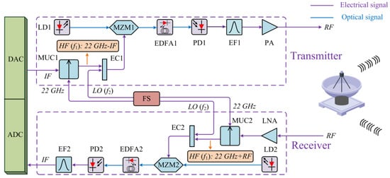
Figure 1.
Schematic diagram of the transceiver using proposed microwave photonic converter (the meanings of the abbreviations in the figure are shown in Table 1).

Table 1.
The meaning of the abbreviations in Figure 1.
The raised microwave photonic converter based on CS-DSB modulation is verified with the following steps. For upconversion, the HF () signal is finished by microwave upconversion of the IF (1.8 GHz) signal using a 22 GHz signal. Simultaneously, the LO () signal is determined by the RF signal. Thus, the transmitting RF point is generated by the beating between and . The downconversion is accomplished through the same method. The output IF of 1.8 GHz is fixed, which is also generated by the mixing between and . In principle, the demonstrated transceiver system presents a better ability to transmit and receive RF signals from 0.8–18 GHz in comparison with the traditional electrical transceiver system.
To achieve the CS-DSB modulation, the MZM has to be biased at the minimum transmission bias (MITB) point. Taking into account the conversion condition mentioned, when we combine the HF signal and LO signal to implement the modulation of a single MZM, the optical field of the MZM can be described by
where is the amplitude of the optical field at the MZM input, is the angular frequency, and are the optical phase difference introduced by and which supply the bias voltages for the upper and lower arms of the MZM, represents the half-wave voltage of the MZM, and represent the modulation depth of the MZM driven by HF and LO signals, respectively and, moreover, and are the angular frequency of HF and LO signals, respectively.
Here, we ignore the higher-order sidebands (≥2) under the small-signal modulation condition. Thus, the CS-DSB modulation of both the HF and LO signals is achieved by mathematical derivation and analyzed in Figure 2a,c. The sideband diagrams show that the optical carrier is suppressed to a low level while double sideband signals have the power of a high level. Next, the frequency conversion is realized via optical-to-electrical conversion and beating making use of a PD, and the photocurrent of the IF signal detected by the PD is given by
where is the responsivity of the PD. Figure 2b,d prove the final conversion effect for both the upconversion and downconversion after beating. It is shown that our system could complete high-quality frequency conversion without any spurs because the mixing spurs with the frequency of (≥20.2 GHz for upconversion, ≥22.8 GHz for downconversion), (≥21 GHz), , , , , and are outside the system frequency range of 0.8–18 GHz.
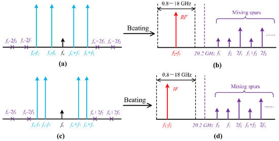
Figure 2.
Schematic diagram of the optical spectrum under CS-DSB modulation, (a) for upconversion, (c) for downconversion, and the electrical spectrum after beating, (b) for upconversion, (d) for downconversion.
3. Simulation Results
A simulation in accordance with Figure 1 is performed through OptiSystem. The linewidth and frequency of the laser are 50 MHz and 193.1 THz, respectively, the output power is 10 dBm. An MZM is adopted in the settings whose upper and lower ports have opposite electrical phases, and the MZM has an extinction ratio of 40 dB. In addition, the switching bias voltage and the bias voltage of the upper arm are set to 6 V in order to carry out CS-DSB modulation. The PD has a responsivity of 0.8 A/W.
The results of upconversion and downconversion are shown in Figure 3 and Figure 4. We assume that the IF signal has a frequency of 1.8 GHz and adjust the frequency of RF to 0.8–18 GHz in the simulation system, which corresponds to LO over 21–38.2 GHz. As can be seen from Figure 3, the modulation optical spectrum of HF signal and LO signal indicates that the CS-DSB modulation is finished by controlling parameters of the dual-port MZM. Between them, the HF signal originates from upconverting the IF/RF signal via a 22 GHz signal. Furthermore, the +1-order sidebands of HF and LO signals exhibit good power consistency and give greater optical power than −20 dBm for both the upconversion and downconversion (Figure 3). The beating frequency from 0–20 GHz is shown in Figure 4a,b. The electrical spectrum illustrates that RF and IF signals produced by upconversion and downconversion, respectively, can obtain an in-band spurious suppression of at least 25 dBc. Near the target signals, no obvious spurs can be observed because the mixing spurs are outside the system frequency range of 0.8–18 GHz. For the flatness of output power, Figure 4c,d show power fluctuation of 2.2 dB for upconversion and 1.88 dB for downconversion within the LO frequency of 21–38.2 GHz. Therefore, from a simulation point of view, the proposed transceiver system demonstrates improved conversion capability by applying the microwave photonic converter.
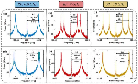
Figure 3.
Simulated optical spectrum of upconversion (a–c) and downconversion (d–f) when RF signal has the frequencies of 0.8 GHz, 9 GHz, and 18 GHz.
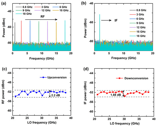
Figure 4.
Simulated electrical spectrum of upconversion (a), downconversion (b), and output power of RF (c), IF (d) signal when RF signal is tuned from 0.8 to 18 GHz.
4. Experimental Results
4.1. Experimental Setup
The experiment based on the setup of Figure 1 is shown in Figure 5. Center wavelength and output optical power of LD are set at 1550.12 nm and 10 dBm, respectively, to satisfy requirements of the link. The laser source is connected to the commercial modulator (ixblue, MXAN-LN-20) so that the optical carrier can be coupled to the MZM. The HF and LO signals are combined by an electrical combiner and drive the arms of the MZM which has a half-wave voltage of 5 V and optical insertion loss of 3.5 dB. An EDFA is connected after the modulated optical path for optical power compensation. The working current of the EDFA is set to 100 mA under an amplification ability of 25 dB. Next, the photoelectric conversion is completed by a PD, and the responsivity is 0.8 A/W, and the bandwidth is 20 GHz to achieve spurious suppression of out-band. In the beat-frequency process, the frequency of HF and LO signals is determined by IF and RF signals. We should note that the IF/RF signal in this experiment is assumed to have been upconverted to HF signal via a 22 GHz signal in advance, because the commercial active microwave upconverters have a spurious suppression ratio of over 60 dBc and a conversion gain of over 3 dB [25,26], and this is good enough to meet our experimental needs.
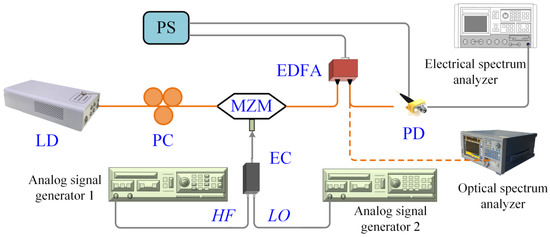
Figure 5.
Experimental link setup based on the proposed converter (PS: power source; PC: polarization controller).
4.2. Optical Spectrum
First of all, the CS-DSB modulation of the proposed microwave photonic converter is analyzed in the optical domain. The modulated optical spectrum of upconversion with an HF signal of 20.2 GHz and LO signal of 35.2 GHz is measured by an optical spectrum analyzer (OSA, YOKOGAWA, AQ6370D). The HF and LO signals are generated by two analog signal generators (ASG, KEYSIGHT E8267D, and ROHDE&SCHWARZ) and the power of both the HF and LO signals is 0 dBm. The optical spectrum under both the MITB and quadrature bias (QB) point is shown in Figure 6. The selected MZM does not exhibit a very strong suppression ability of the carrier because the MZM has a relatively small extinction ratio (30 dB). Compared with the double-sideband (DSB) modulation described with the short-dashed line, the CS-DSB modulation delineated with the solid line demonstrates a suppression (16.8 dB) of the central optical carrier. It is beneficial to the amplification of sideband signals by the EDFA. The orange lines in Figure 6 display a strength improvement of 13.5 dB for the +1-order sideband signal of 20.2 GHz through the EDFA. The optical spectrum indicates that the MZM can output a good CS-DSB modulation signal after the EDFA. The optical carrier is suppressed by simply controlling the bias voltage of the modulator, which is different from the use of optical filter. In [27], optical filters are used to filter out unexpected optical carriers. However, the approach is limited by the requirement of the high stopband rejection level filter at the optical carrier wavelength and a very narrow bandwidth. Thus, the drawbacks will result in effects on the RF and LO sidebands when filtering. On the other hand, the modulation sidebands of the LO 35.2 GHz signal exhibit power attenuation of around 10 dB compared to the HF 20.2 GHz signal. This situation is due to two reasons, one is the increased loss of electrical devices including electrical cable and electrical combiner at the high frequency, the other is that the modulation capability of the modulator itself is weakened when frequency increases. The power responses of the electrical devices and MZM will be described and analyzed later.
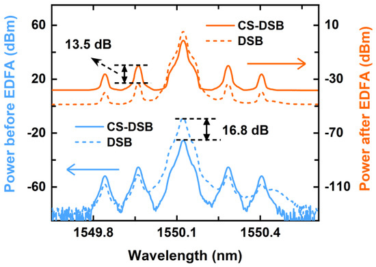
Figure 6.
Measured optical spectrum before and after EDFA.
4.3. Electrical Spectrum
The purity of the electrical spectrum is evaluated by an electrical spectrum analyzer (ESA, ROHDE&SCHWARZ) with a resolution bandwidth of 3 kHz. The measured output spectrum of both the upconversion and downconversion is described in Figure 7a,b where the transmitted and received RF signals have a frequency of 0.8 GHz, 3 GHz, 6 GHz, 9 GHz, 12 GHz, 15 GHz, and 18 GHz, respectively. It can be seen that the target signals obtained are very pure and have spurious suppression of more than 40 dBc at the in-band 0.8–18 GHz. This is thanks to microwave pre-treatment of the upconversion and the spectrum locations of all the unwanted mixing spurs are over 18 GHz.
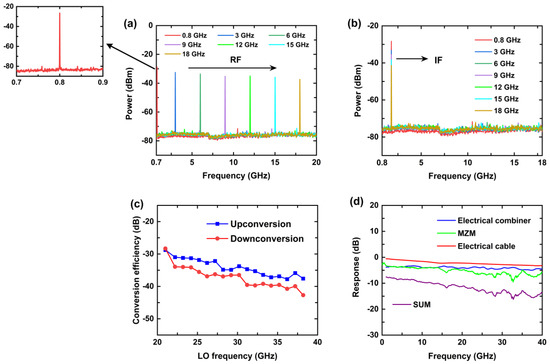
Figure 7.
Measured output electrical spectrum of both the upconversion (a) and downconversion (b) when RF signal is tuned from 0.8 to 18 GHz. Conversion efficiency (c) when LO frequency is tuned from 21–38.2 GHz (corresponds to the RF signal from 0.8–18 GHz) and power responses (d) of electrical cable, electrical combiner, and MZM.
The conversion efficiency is defined by the ratio of the output RF/IF signal power to the input HF signal power, which represents the power response of the proposed microwave photonic converter. The LO frequency is tuned from 21–38.2 GHz in order to measure the conversion efficiency shown in Figure 7c. Furthermore, the power of the HF and LO signals is fixed at 0 dBm, which is in the linear response region of the whole system. We can see that the conversion efficiency reduces with the increase in the LO frequency for both the upconversion and downconversion. Additionally, due to higher frequency of the HF signal in the downconversion process, a disparity emerges between upconversion and downconversion. To further analyze the influencing factors of conversion efficiency, the power responses of the electrical cable, electrical combiner, and the MZM are measured and described in Figure 7d. Combined with the response curves, we find that the transmission responses of all three drop at high frequencies and introduced microwave loss reaches 3.2 dB, 4.5 dB, and 5.8 dB, respectively, at 40 GHz, which coincides with the downtrend of the conversion efficiency. The microwave photonic converter with the high conversion efficiency is applied in practice. To realize this, in addition to the use of the components with greater bandwidth, a PD with higher gain, or an SOA and an EDFA in series, can also be considered.
4.4. Dynamic Range
Dynamic range is another important characterization parameter for transceivers to perform the anti-interference and anti-distortion capability of the system. The dynamic range includes linear dynamic range (LDR) and spurious-free dynamic range (SFDR). LDR is the difference value between 1 dB power compression point (P-1) and noise power, and SFDR is the ratio of fundamental signal power to noise floor power when the third-order intermodulation distortion (IMD3) is equal to the noise floor power. We assume that the RF operating point of the system is 9 GHz. Thus, the input 1 dB power compression point (IP-1) is shown in Figure 8a,b with the HF 20.2 GHz for upconversion and HF 31 GHz for downconversion. The results of 13 dBm and 9.5 dBm are acquired by measuring and fitting. To test the SFDR of the system, a two-tone signal with a spacing of 1 MHz is adopted to drive the MZM. As shown in Figure 9a,b, SFDR is up to 86.23 dB·HZ2/3 and 80.95 dB·HZ2/3, respectively, for upconversion and downconversion. Therefore, the IP-1 and SFDR of our converter are sufficient for most practical transceiver applications.
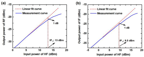
Figure 8.
Input 1 dB power compression point (IP-1), (a) for upconversion and (b) for downconversion.
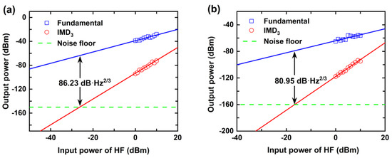
Figure 9.
Spurious-free dynamic range (SFDR), (a) for upconversion and (b) for downconversion.
4.5. Comparison
A comparison of the conversion ability of several microwave photonic converters was completed and the results are presented in Table 2. In [28,29,30], the research was carried out based only on the downconversion, and practical application as a transceiver is limited. Apart from this, the bandwidth limiting factors, including optical and electrical devices, are more than the proposed microwave photonic converter for the entire system. Considering the purity of the electrical spectrum, we find that [28,30] just show spurious suppression within a fraction of the bandwidth, but our converter has a suppression ratio of the mixing spurs >40 dBc in the whole in-band of 0.8–18 GHz.

Table 2.
Comparison of the conversion ability of several microwave photonic converters.
On the other hand, we compared the proposed microwave photonic converter to the traditional electrical conversion utilizing an MUC + EF setup. Generally, the traditional electrical converter needs multi-stage conversion when it is used in a transceiver. The one-stage electrical conversion system cannot cover the whole band of 0.8–18 GHz, which means an increase in the system complexity. In order to expand the conversion bandwidth and the number of parallel processing signals, the traditional microwave frequency conversion system needs to continuously increase the number of antennas. Thus, the costs and size will increase. However, the microwave photonics frequency conversion system used in our system does not significantly increase device count as processing demands increase. Therefore, from this perspective, our system is simpler than the MUC + EF setup [31].
5. Discussion
Since the responsiveness of the PD used in our system is small (0.8 A/W), the conversion efficiency is relatively low, and we did not take the microwave upconverter and electrical filter (MUC + EF) into consideration. Thus, the whole conversion loss should be larger than 35 dB. There are several solutions to further improve the conversion efficiency. One is to use an active microwave upconverter [32] which could provide additional conversion gain (~3 dB), the other is to use electrical amplification after the PD, but the increased noise power and appearance of spurious signals will be another problem.
Bandwidth is another factor that must be considered when the proposed scheme is used in radar systems. In addition to the space field, the bandwidth of the L-Ku band is sufficient for most radars, for example, warning radar [33], and civil aviation radar [34,35]. On the other hand, in this paper, we sacrifice nearly half of the bandwidth in order to obtain high in-band spurious rejection (0.8–18 GHz). The main limiting factors of bandwidth come from MZM and PD, and today’s modulators [36] and detectors [37] can achieve a bandwidth of over 100 GHz. Therefore, for the application in the space field, we just replace the MZM and PD in this experiment with the modulator and detector of higher bandwidth.
In practice, the DAC/ADC may be located in an office away from the radar. The effects of fiber dispersion should be considered when the fiber has sufficient length [38]. When we consider analog signal transmission, fiber dispersion creates a time delay between adjacent signals. That will increase phase difference , and then cause the amplitude of the synthetic wave to drop. The higher the modulation frequency , the larger the phase shift and the loss. Therefore, this limits the transmission bandwidth. To solve the problem introduced by dispersion, dispersion compensation techniques, such as Bragg grating dispersion compensation [39], chirp compensation [40], and dispersion compensation fiber (DCF) [41], are necessary in the application.
6. Conclusions
In this paper, we proposed a microwave photonic converter based on microwave pre-upconversion. The transmitted and received signals before entering the MZM are upconverted to HF by microwave pre-treatment. The HF and LO signals are coupled to drive the MZM by means of the electrical combiner, and CS-DSB modulation is introduced to the MZM by simply controlling the bias voltages of the modulator. Only a single MZM is employed in the converter system so that the complexity and bandwidth limiting in the link can be reduced. Experimental results demonstrate that the interference components including harmonics and intermodulation as well as original signals are all out of the system frequency band from 0.8–18 GHz, and in-band spurious suppression of at least 40 dBc is achieved. In addition, the system has SFDR of 86.23 dB·HZ2/3 for upconversion and 80.95 dB·HZ2/3 for downconversion. The proposed system shows improved conversion capability for both the upconversion and downconversion in the applications of radars and microwave signal processing.
Author Contributions
Conceptualization, Y.Z., W.W. and W.Z.; hardware, C.W. and Q.J.; validation, Y.Z., W.Z. and Z.Z.; writing—original draft preparation, C.W.; writing—review and editing, C.W., W.W. and Y.Z.; project administration, J.L.; C.W. and Y.Z. contributed equally to this work. All authors have read and agreed to the published version of the manuscript.
Funding
This work is supported by the National Natural Science Foundation of China (61727815).
Acknowledgments
The authors are grateful to the State Key Laboratory on Integrated Optoelectronics, Institute of Semiconductors, Chinese Academy of Sciences and School of Integrated Circuits, University of Chinese Academy of Sciences.
Conflicts of Interest
The funders had no role in the design of the study; in the collection, analyses, or interpretation of data; in the writing of the manuscript, or in the decision to publish the results.
References
- Zhang, H.; Wang, Y.; Yang, D.; Yang, F.; Wang, D. A Microwave Photonic Downconverter with the Third-order Distortion Suppression. In Proceedings of the Laser Science 2019, Washington, DC, USA, 15–19 September 2019. Paper JW3A.116. [Google Scholar] [CrossRef]
- Lin, C.-M.; Lin, H.-K.; Lin, C.-F.; Lai, Y.-A.; Lin, C.-H.; Wang, Y.-H. A 16–44 GHz Compact Doubly Balanced Monolithic Ring Mixer. IEEE Microw. Wirel. Compon. Lett. 2008, 18, 620–622. [Google Scholar] [CrossRef]
- Helmy, A.; Sharaf, K.; Ragai, H. Analysis and optimization of noise in bipolar RF harmonic mixers. In Proceedings of the 44th IEEE 2001 Midwest Symposium on Circuits and Systems, MWSCAS 2001 (Cat. No. 01CH37257), Dayton, OH, USA, 14–17 August 2002; Volume 2, pp. 829–832. [Google Scholar] [CrossRef]
- Verma, A.; Gao, L.; Lin, J. A K-band down-conversion mixer with 1.4-GHz bandwidth in 0.13-µm CMOS technology. IEEE Microw. Wirel. Compon. Lett. 2005, 15, 493–495. [Google Scholar] [CrossRef]
- Yang, T.-Y.; Chiou, H.-K. A 16–46 GHz Mixer Using Broadband Multilayer Balun in 0.18-µm CMOS Technology. IEEE Microw. Wirel. Compon. Lett. 2007, 17, 534–536. [Google Scholar] [CrossRef]
- Chan, E.H.W.; Minasian, R.A. Microwave Photonic Downconverter with High Conversion Efficiency. J. Light. Technol. 2012, 30, 3580–3585. [Google Scholar] [CrossRef]
- Capmany, J.; Novak, D. Microwave photonics combines two worlds. Nat. Photonics 2007, 1, 319–330. [Google Scholar] [CrossRef]
- Brunetti, G.; Dell’Olio, F.; Conteduca, D.; Armenise, M.N.; Ciminelli, C. Ultra-Compact Tuneable Notch Filter Using Silicon Photonic Crystal Ring Resonator. J. Light. Technol. 2019, 37, 2970–2980. [Google Scholar] [CrossRef]
- Yao, J. Photonics to the Rescue: A Fresh Look at Microwave Photonic Filters. IEEE Microw. Mag. 2015, 16, 46–60. [Google Scholar] [CrossRef]
- Minasian, R.A.; Yi, X. Advances in Microwave Photonic Beamforming for Phased-Array Antennas. In Proceedings of the 2019 21st International Conference on Transparent Optical Networks (ICTON), Angers, France, 9–13 July 2019; pp. 1–4. [Google Scholar] [CrossRef]
- Zhu, C.; Lu, L.; Shan, W.; Xu, W.; Zhou, G.; Zhou, L.; Chen, L. Silicon integrated microwave photonic beamformer. Optica 2020, 7, 1162. [Google Scholar] [CrossRef]
- Yao, J. Photonic generation of microwave arbitrary waveforms. Opt. Commun. 2011, 284, 3723–3736. [Google Scholar] [CrossRef]
- Krishnan, A.; Knapczyk, M.; De Peralta, L.; Bernussi, A.; Temkin, H. Reconfigurable direct space-to-time pulse-shaper based on arrayed waveguide grating multiplexers and digital micromirrors. IEEE Photonics Technol. Lett. 2005, 17, 1959–1961. [Google Scholar] [CrossRef]
- McKinney, J.D.; Leaird, D.E.; Weiner, A.M. Millimeter-wave arbitrary waveform generation with a direct space-to-time pulse shaper. Opt. Lett. 2002, 27, 1345–1347. [Google Scholar] [CrossRef] [PubMed]
- Brunetti, G.; Armenise, M.N.; Ciminelli, C. Chip-Scaled Ka-Band Photonic Linearly Chirped Microwave Waveform Generator. Front. Phys. 2022, 10, 158. [Google Scholar] [CrossRef]
- Gopalakrishnan, G.; Burns, W.; Bulmer, C. Microwave-optical mixing in LiNbO/sub 3/modulators. IEEE Trans. Microw. Theory Technol. 1993, 41, 2383–2391. [Google Scholar] [CrossRef]
- Gallo, J.; Godshall, J. Comparison of series and parallel optical modulators for microwave down-conversion. IEEE Photonics Technol. Lett. 1998, 10, 1623–1625. [Google Scholar] [CrossRef]
- Wang, Y.; Li, J.; Wang, D.; Zhou, T.; Xu, J.; Zhong, X.; Yang, D.; Rong, L. Ultra-wideband microwave photonic frequency downconverter based on carrier-suppressed single-sideband modulation. Opt. Commun. 2018, 410, 799–804. [Google Scholar] [CrossRef]
- Zhang, T.; Zhang, F.; Chen, X.; Pan, S. A simple microwave photonic downconverter with high conversion efficiency based on a polarization modulator. In Proceedings of the 2014 Asia Communications and Photonics Conference (ACP), Shanghai, China, 11–14 November 2014. Paper AF2E.4. [Google Scholar] [CrossRef]
- Jiang, W.; Zhao, S.; Tan, Q.; Li, X.; Liang, D.; Range, D. Wideband microwave photonic downconverter with low phase noise and improved spurious-free. In Proceedings of the 2017 International Topical Meeting on Microwave Photonics (MWP), Beijing, China, 23–26 October 2017; pp. 1–4. [Google Scholar] [CrossRef]
- Xu, J.; Wang, Y.; Zhou, T.; Wang, D.; Li, J.; Zhong, X.; Yang, D. Microwave photonic frequency downconverter based on single sideband modulation. In Proceedings of the AOPC 2017: Fiber Optic Sensing and Optical Communications, Beijing, China, 4–6 June 2017. [Google Scholar]
- Qiao, Y.; Li, H.; Hu, X.; Gong, C.; Sun, K.; Wei, Y. Microwave Photonic Sub-harmonic Downconverter with Image Rejection Capability. In Proceedings of the 2019 IEEE 4th Optoelectronics Global Conference (OGC), Shenzhen, China, 3–6 September 2019; pp. 40–44. [Google Scholar] [CrossRef]
- Shen, J.; Wu, G.; Zou, W.; Chen, R.; Chen, J. Linear and stable photonic radio frequency phase shifter based on a dual-parallel Mach–Zehnder modulator using a two-drive scheme. Appl. Opt. 2013, 52, 8332–8337. [Google Scholar] [CrossRef]
- Lei, M.; Gao, X.; Zhao, M.; Huang, S. A Phase-Tunable Microwave Phonic Downconverter Based on Double-Sideband Modulation of Radio Frequency Signal and Local Oscillator Signal. In Proceedings of the Asia Communications and Photonics Conference 2017, Guangzhou, China, 10–13 November 2017. Paper S4E.5. [Google Scholar] [CrossRef]
- Liu, Y.; Lu, W.; Cheng, S.; Cao, S.; Zhou, X.F. A 0.18 um 3.3 mW double-balanced CMOS active mixer. In Proceedings of the 2007 7th International Conference on ASIC, Guilin, China, 22–25 October 2007; pp. 419–422. [Google Scholar] [CrossRef]
- Tu, Z.; Xu, J.; Chen, K.; Lei, O.; Zhang, X. Design of a X-band Frequency-Conversion Front-End T/R Module. In Proceedings of the 2018 China International SAR Symposium (CISS), Shanghai, China, 10–12 October 2018; pp. 1–3. [Google Scholar] [CrossRef]
- Haas, B.M.; Murphy, T.E. Linearized Downconverting Microwave Photonic Link Using Dual-Wavelength Phase Modulation and Optical Filtering. IEEE Photonics J. 2011, 3, 1–12. [Google Scholar] [CrossRef]
- Zhang, J.; Chan, E.; Wang, X.; Feng, X.; Guan, B.-O. Broadband Microwave Photonic Sub Harmonic Downconverter with Phase Shifting Ability. IEEE Photonics J. 2017, 9, 5501910. [Google Scholar] [CrossRef]
- Haas, B.M.; Murphy, T.E. A carrier-suppressed phase-modulated fiber optic link with IF downconversion of 30 GHz 64-QAM signals. In Proceedings of the 2009 International Topical Meeting on Microwave Photonics, Valencia, Spain, 14–16 October 2009; pp. 1–4. [Google Scholar]
- Shan, D.; Wen, A.; Zhai, W.; Li, X.; Zhang, W.; Tu, Z. Filter-free image-reject microwave photonic downconverter based on cascaded modulators. Appl. Opt. 2019, 58, 3432–3437. [Google Scholar] [CrossRef]
- Sun, C.; Orazi, R.; Pappert, S. Efficient microwave frequency conversion using photonic link signal mixing. IEEE Photonics Technol. Lett. 1996, 8, 154–156. [Google Scholar] [CrossRef]
- Bhatt, D. Design of Wideband Active Mixer by using an Active Inductor. In Proceedings of the 2019 IEEE Asia-Pacific Microwave Conference (APMC), Singapore, 10–13 December 2019; pp. 1173–1175. [Google Scholar] [CrossRef]
- Skolnik, M.I. Radar Handbook; McGraw-Hill, Inc.: London, UK, 2008; pp. 12–15. [Google Scholar]
- Pujol, O.; Mesnard, F.; Sauvageot, H. Effects of Melting Layer in Airborne Meteorological X-Band Radar Observations. IEEE Trans. Geosci. Remote Sens. 2012, 50, 2318–2324. [Google Scholar] [CrossRef]
- Evers, C.; Smith, A.; Lee, D. Application of radar multistatic techniques to air traffic control. In Proceedings of the Record of the IEEE, 2000 International Radar Conference [Cat. No. 00CH37037], Alexandria, VA, USA, 12 May 2002; pp. 763–768. [Google Scholar] [CrossRef]
- He, M.; Xu, M.; Ren, Y.; Jian, J.; Ruan, Z.; Xu, Y.; Gao, S.; Sun, S.; Wen, X.; Zhou, L.; et al. High-performance hybrid silicon and lithium niobate Mach–Zehnder modulators for 100 Gbit s−1 and beyond. Nat. Photonics 2019, 13, 359–364. [Google Scholar] [CrossRef]
- Li, Q.; Sun, K.; Li, K.; Yu, Q.; Zang, J.; Wang, Z.; Runge, P.; Ebert, W.; Beling, A.; Campbell, J.C. Waveguide-integrated high-speed and high-power photodiode with >105 GHz bandwidth. In Proceedings of the 2017 IEEE Photonics Conference (IPC), Orlando, FL, USA, 1–5 October 2017; pp. 49–50. [Google Scholar] [CrossRef]
- Henry, P. Lightwave primer. IEEE J. Quantum Electron. 1985, 21, 1862–1879. [Google Scholar] [CrossRef]
- Inui, T.; Komukai, T.; Nakazawa, M.; Suzuki, K.; Tamura, K.; Uchiyama, K.; Morioka, T. Adaptive dispersion slope equalizer using a nonlinearly chirped fiber Bragg grating pair with a novel dispersion detection technique. IEEE Photonics Technol. Lett. 2002, 14, 549–551. [Google Scholar] [CrossRef]
- Lanne, S.; Penninckx, D.; Thiery, J.-P.; Hamaide, J.-P. Impact of chirping on polarization-mode dispersion compensated systems. IEEE Photonics Technol. Lett. 2000, 12, 1492–1494. [Google Scholar] [CrossRef]
- Dong, B.; Wei, L.; Zhou, D.-P. Coupling Between the Small-Core-Diameter Dispersion Compensation Fiber and Single-Mode Fiber and Its Applications in Fiber Lasers. J. Light. Technol. 2010, 28, 1363–1367. [Google Scholar] [CrossRef]
Publisher’s Note: MDPI stays neutral with regard to jurisdictional claims in published maps and institutional affiliations. |
© 2022 by the authors. Licensee MDPI, Basel, Switzerland. This article is an open access article distributed under the terms and conditions of the Creative Commons Attribution (CC BY) license (https://creativecommons.org/licenses/by/4.0/).