Article

Nonlinear Error Correction for Color Phase-Shifting Profilometry with Histogram Equalization

1
School of Internet, Anhui University, Hefei 230039, China
2
Key Laboratory of Icing and Anti/De-Icing, China Aerodynamics Research and Development Center, Mianyang 621000, China
3
National Engineering Research Center for Agro-Ecological Big Data Analysis and Application, Anhui University, Hefei 230601, China
4
College of Engineering, Anhui Agricultural University, Hefei 230036, China
*
Author to whom correspondence should be addressed.
Photonics 2022, 9(6), 385; https://doi.org/10.3390/photonics9060385
Submission received: 12 April 2022 / Revised: 22 May 2022 / Accepted: 25 May 2022 / Published: 30 May 2022
(This article belongs to the Special Issue Optical 3D Sensing Systems)

Abstract

:
Because color patterns with multiple channels can carry more information than gray patterns with only one channel, color phase-shifting profilometry (CPSP) has been widely used for high-speed, three-dimensional (3D) shape measurement. However, the accuracy of CPSP suffers from nonlinear errors caused by color crosstalk. This paper presents an effective nonlinear error correction method for CPSP based on histogram equalization. The two main steps of the proposed method are eliminating nonlinear errors with histogram equalization and optimizing the results using a spline fitting algorithm. Compared with other compensation methods, the proposed approach does not require any precalibration information or additional patterns, which are very time-consuming. The simulations and experiments indicate that the proposed method has a promising performance for nonlinear error elimination.

1. Introduction

As an important contactless optical metrology technique, fringe projection profilometry (FPP) based on the structured light technique has continuously attracted much attention from scholars in recent years [1,2,3]. FPP possesses the merits of offering fast speed and high accuracy such that it has been applied in various fields, such as reverse engineering, biomedical engineering, and online detection [4,5,6]. A typical FPP system consists of a projector used to project the designed patterns and a camera used to capture the deformed fringes. Three-dimensional (3D) geometry of the tested objects can be derived from the deformed images. Phase-shifting is more accurate and robust in comparison with a transform-based algorithm and is broadly used to retrieve phase maps in FPP [7]. However, a phase-shifting algorithm usually requires three or more fringe patterns to complete measurements, which limits its measuring efficiency [8]. Accordingly, color phase-shifting profilometry (CPSP) has been proposed to address these issues. CPSP frequently uses a three-step phase-shifting method since it requires the least number of projected patterns, and it encodes them into R (red), G (green), and B (blue) channels to form one color image, which allows the simultaneous acquisition of three phase-shifting patterns to realize one-shot measurement [9].
Generally, a color imaging device has no colorblind areas on the spectrum; due to the spectra of R, G, and B, the channels are usually made to have some overlap [10]. Unfortunately, this induces crosstalk between the three different channels. The coupling effects can distort the intensities of the captured patterns and introduce nonlinear phase errors in the final phase map [11]. A detailed analysis of the nonlinearity in CPSP is described in Section 2.2. To eliminate the errors caused by color coupling or crosstalk, many nonlinear correction methods have been proposed. Kinell [12] introduced a direct method to compensate for the errors. The R, G, and B channels were calibrated individually, and the difference between distorted phases and reference phases was used to establish a look-up table (LUT) for compensation. Huang et al. [13] calculated the modulation degrees of the R, G, and B channels, respectively. The coefficients between the three different channels were determined and used to compensate for nonlinear errors. Zhang et al. [14] introduced a CPSP method using extra images to compute the distorted curves to correct the errors and reserved the color information of the object. Wan et al. [15] proposed an active phase error suppression method for color phase-shifting fringe projection based on hue precorrection. Wu et al. [16] presented a point-to-point method based on the correspondence between camera pixels and projector pixels to accomplish the compensation of the full field. However, those methods require extra images with prior knowledge to calculate the compensation factors, which means that once the measuring condition changes, the calibration process is repeated.
Additionally, some methods without calibration have also been proposed. Hu et al. [17] estimated a color demixing matrix based on the color fringe patterns captured from a reference plane or the surface of an object without extra images. Ma et al. [18] presented a blind phase error suppression approach based on isotropic n-dimensional fringe pattern normalization and carrier squeezing interferometry. Flores et al. [19] implemented a pattern normalization algorithm to achieve the intensity modulation balance and an iterative algorithm to retrieve the phase. Naturally, the methods described above take more time to complete the calculations. Alternatively, Wang et al. [20] first applied the Hilbert transform to CPSP and improved the measurement accuracy with little computation. However, the Hilbert-transform-based method is sensitive to sharp edges or discontinuous parts. Thus, methods without calibration usually require complex calculations or strict working conditions.
This paper proposes a nonlinear error compensation method for CPSP with histogram equalization. The proposed method eliminates the phase errors without a calibration process or additional images. Meanwhile, the calculation is also simple, which has a positive effect on the measuring speed. Generally, a histogram of an undistorted phase is uniform, but that of a distorted phase becomes nonuniform. Thus, the distorted phase can be corrected by directly applying histogram equalization. Accordingly, the first step is directly applying histogram equalization to the wrapped phase, and the nonlinear phase error caused by crosstalk can be compensated for roughly. Then, a spline interpolation optimization is implemented to further eliminate the discretization error and smooth the phase. The simulations and experiments validate the efficiency of the proposed method.

2. Principle

2.1. Color Phase-Shifting Profilometry

Employing color fringe patterns in fringe projection profilometry is the so-called color phase-shifting profilometry (CPSP). Three fringe patterns with 2π/3 phase shifts are encoded into the R, G, and B channels of a color fringe and then projected onto a measured object surface by a projector [21]. Because of the modulation of object surfaces, the color fringe is deformed and then captured by a camera. The 3D shape of the measured object relative to the reference plane can be reconstructed by a combination of fringe analysis and projector–camera system calibration. A three-step phase-shifting algorithm that only requires three fringe patterns suits a color fringe pattern with R, G, and B channels. Generally, the projected color fringe pattern can be described as follows:
I r p ( x p , y p ) = a + b cos ( 2 π x p / T 2 π / 3 )
I g p ( x p , y p ) = a + b cos ( 2 π x p / T )
I b p ( x p , y p ) = a + b cos ( 2 π x p / T + 2 π / 3 )
where ( x p , y p ) represents the projector pixel; a , b are two constants; T is the number of pixels per fringe period; and Φ p = 2 π x p / T represents the absolute phase that increases linearly with x p . Ideally, the intensities of three channels of the captured color fringe pattern can be described as follows:
I r ( x , y ) = A ( x , y ) + B ( x , y ) cos [ ϕ ( x , y ) 2 π / 3 ]
I g ( x , y ) = A ( x , y ) + B ( x , y ) cos [ ϕ ( x , y ) ]
I b ( x , y ) = A ( x , y ) + B ( x , y ) cos [ ϕ ( x , y ) + 2 π / 3 ]
where I r , I g , and I b are the intensities of the R, G, and B channels, respectively; A represents the average intensity; B represents the intensity modulation; and ϕ represents the wrapped phase that is being solved. Combining the three equations leads to:
ϕ ( x , y ) = tan 1 [ 3 I r ( x , y ) I b ( x , y ) 2 I g ( x , y ) I r ( x , y ) I b ( x , y ) ]
The arctangent function results in ϕ ranging from 0 to 2π with 2π discontinuities. Therefore, a phase-unwrapping process is carried out to remove these 2π discontinuities. The absolute phase can be calculated as:
Φ ( x , y ) = ϕ ( x , y ) + 2 π × k ( x , y )
where k is an integer often known as the fringe order. This paper used an enhanced two-frequency phase-shifting algorithm for phase unwrapping. Once we obtained the absolute phase relating to an object’s surface, the 3D shape could be reconstructed by mapping the phase distribution into the 3D-world coordinates.

2.2. Nonlinear Phase Error Analysis

Projectors and cameras usually to have some overlaps among the spectra of the color channels to avoid colorblind regions in the spectrum [22]. Color crosstalk is a major phase error source for color phase-shifting profilometry. In general, a color fringe pattern distorted by color crosstalk can be described as [23]:
[ I r ( x , y ) I g ( x , y ) I b ( x , y ) ] = [ κ r r κ r g κ r b κ g r κ g g κ g b κ b r κ b g κ b b ] [ I r ( x , y ) I g ( x , y ) I b ( x , y ) ]
where κ represents the color crosstalk matrix. For a color projector, the elements of its crosstalk matrix κ are constant. For a color camera, the elements of its crosstalk matrix κ can be also regarded as constant if measuring a monochromatic object. Furthermore, considering the color crosstalk of both the projector and the camera, the distorted color fringe pattern can be described as:
[ I ˜ r ( x , y ) I ˜ g ( x , y ) I ˜ b ( x , y ) ] = [ κ r r c κ r g c κ r b c κ g r c κ g g c κ g b c κ b r c κ b g c κ b b c ] [ κ r r p κ r g p κ r b p κ g r p κ g g p κ g b p κ b r p κ b g p κ b b p ] [ I r ( x , y ) I g ( x , y ) I b ( x , y ) ]
where κ p and κ c are the color crosstalk matrices of the projector and camera, respectively. For the sake of simplicity, we used ϕ ( x , y ) = f 1 [ I r , I g , I b ] to substitute for Equation (7) and [ I ˜ r , I ˜ g , I ˜ b ] = f 2 [ I r , I g , I b ] to substitute for Equation (11). Therefore, the distorted wrapped phase can be calculated as:
ϕ ˜ ( x , y ) = f 1 [ I ˜ r , I ˜ g , I ˜ b ] = f 1 { f 2 [ I r , I g , I b ] }
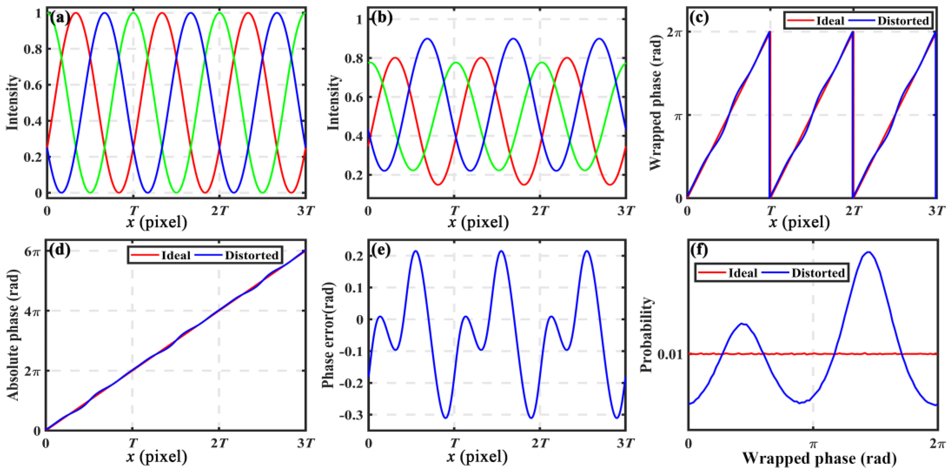
Since the parameters of functions f 1 and f 2 are constant for a fixed CPSP system, there exists a one-to-one mapping relationship between the distorted ϕ ˜ and the ideal ϕ . From Equations (1)–(3), the intensity of the fringe only depends on the x taken into consideration, and the slight difference caused by the variable y was omitted in this paper. Therefore, the results shown in Figure 1 only consider x. Figure 1a shows the intensity distributions of three channels for one ideal color fringe, and the intensity distribution of a distorted pattern is illustrated in Figure 1b. Figure 1c plots the cross-sections of the ideal ϕ and the distorted ϕ ˜ . Figure 1d plots the cross-sections of the ideal Φ and the distorted Φ ˜ . It is obvious that the distorted ϕ ˜ and the ideal ϕ had the same period with a slight misalignment, and the distorted ϕ ˜ with the same phase values at different periods had the same nonlinear error. Figure 1e plots the cross-sections of the nonlinear error, which can be calculated as:
Δ ϕ ˜ ( x , y ) = ϕ ˜ ( x , y ) ϕ ( x , y )
In addition, the distorted ϕ ˜ stayed monotonic but became nonlinear within each period. Thus, it could be used to uniquely identify each pixel within one fringe period.

2.3. Proposed Correction Method with Histogram Equalization

As introduced above, the absolute phase is Φ p = 2 π x p / T in the projector space, so the absolute phase is continuous. Since x p is the coordinate of the projector pixel with an equal sampling interval, the phase probability distribution (PPD) of Φ p is uniform. If Φ p is wrapped into [ 0 , 2 π ] as the wrapped phase ϕ p in the projector space, the PPD of ϕ p is also uniform because of its periodicity. Ideally, the phase ϕ retrieved from the captured images is the same as the phase ϕ p in the projector space. Thus, the PDDs of the phase map in two different image spaces are equal when the number of sampling intervals is identical. Here, we define an object function to describe the PPD of the wrapped phase:
p ( m ) = P { 2 π m 1 M ϕ < 2 π m M }
where m = 1 , 2 , , M ; M is the number of the sampling intervals from 0 to 2π; p ( m ) represents the probability distribution function; and P { } represents probability. For example, if M = 100 , p ( m ) should be 1 / M = 0.01 for the ideal ϕ . As illustrated in Figure 1f, the ideal PPD curve with M = 100 was parallel to the x-axis because the phase values within each sampling interval had the same probability. However, the color crosstalk introduces the phase error Δ ϕ into the ideal ϕ in practice. Moreover, the phase error Δ ϕ ˜ increases the probability of some phase values while decreasing that of some other phase values. As illustrated in Figure 1f, it is apparent that the nonlinearity effects modified the PDD curve dramatically, and the distorted PPD curve was no longer uniform. It is natural to correct the nonlinear error by adjusting the distorted PPD so that the corrected PPD conforms to the ideal PPD. Histogram equalization provides an effective way of PPD adjustment. Once p ( m ) is obtained, the cumulative PPD can be calculated as:
q ( m ) = i = 1 m p ( i )
Note that 0 q ( m ) 1 . Then, the number corresponding to the input m is:
r ( m ) = r o u n d [ M × q ( m ) ]
where round[●] returns the closest integer, r ( m ) is a mapping function to determine the interval of a point after transformation, and 0 r ( m ) M . If the distorted phase ϕ ˜ satisfies the condition 2 π ( m 1 ) / M ϕ ˜ < 2 π m / M , the corresponding corrected phase after PPD adjustment is:
ϕ ¯ = r ( m ) × 2 π / M

2.4. Accuracy Optimization with Spline Fitting

To guarantee the accuracy of the nonlinear correction, an optimized algorithm based on spline fitting was implemented in our proposed method. Since the output numbers r ( m ) of Equation (16) are discrete integers, the corrected ϕ ¯ computed by Equation (17) has some discrete values with a certain interval of 2 π / M . However, the ideal ϕ has continuous values. This difference leads to a residual error as:
Δ ϕ ¯ ( x , y ) = ϕ ¯ ( x , y ) ϕ ( x , y )
Without considering the effects of random noises, the corrected ϕ ¯ is the discrete results of the ideal ϕ . Therefore, Δ ϕ ¯ can be regarded as the discretization error, and the maximum value is:
max [ Δ ϕ ¯ ( x , y ) ] = π / M
This equation indicates that the residual error Δ ϕ ¯ can be restrained by increasing the number M in theory. To eliminate the discretization errors, an algorithm based on spline fitting is applied:
V i n = s p l i n e ( V h , V m )
where spline[●] denotes the cubic spline interpolation function; V h = [ V h 1 , V h 2 , , V h k ] and V h k are the discrete values of the phases after histogram equalization; V m = [ V m 1 , V m 2 , , V m k ] and V m k are the mean values of the distorted phase corresponding to each discrete value V h k ; and V i n is the initial accurate phase after spline fitting. Then, the median value V i m between V h and V m is also computed. The final accurate phase can be obtained as:
V f = { V i n ,       i f | V i n V i m | ( π / 2 M ) ( V i n + V i m ) / 2 ,             o t h e r w i s e
where V f is the final accurate phase, and M is the number of the sampling intervals.

3. Simulations

Some simulations were conducted to verify the performance of the proposed nonlinear error correction method. The simulated color fringe pattern had 400 × 600 pixels with a fringe period of T = 200 pixels. Figure 2a shows the ideal pattern without any distortions. As described above, color crosstalk was regarded as the main factor for inducing nonlinear error in this paper. Therefore, in the following simulations, the gamma value was set as 1.0 , and the color crosstalk matrix κ of the system was set as [18]:
κ = [ 0.75 0.15 0.05 0.20 0.7 0.10 0.10 0.20 0.85 ]
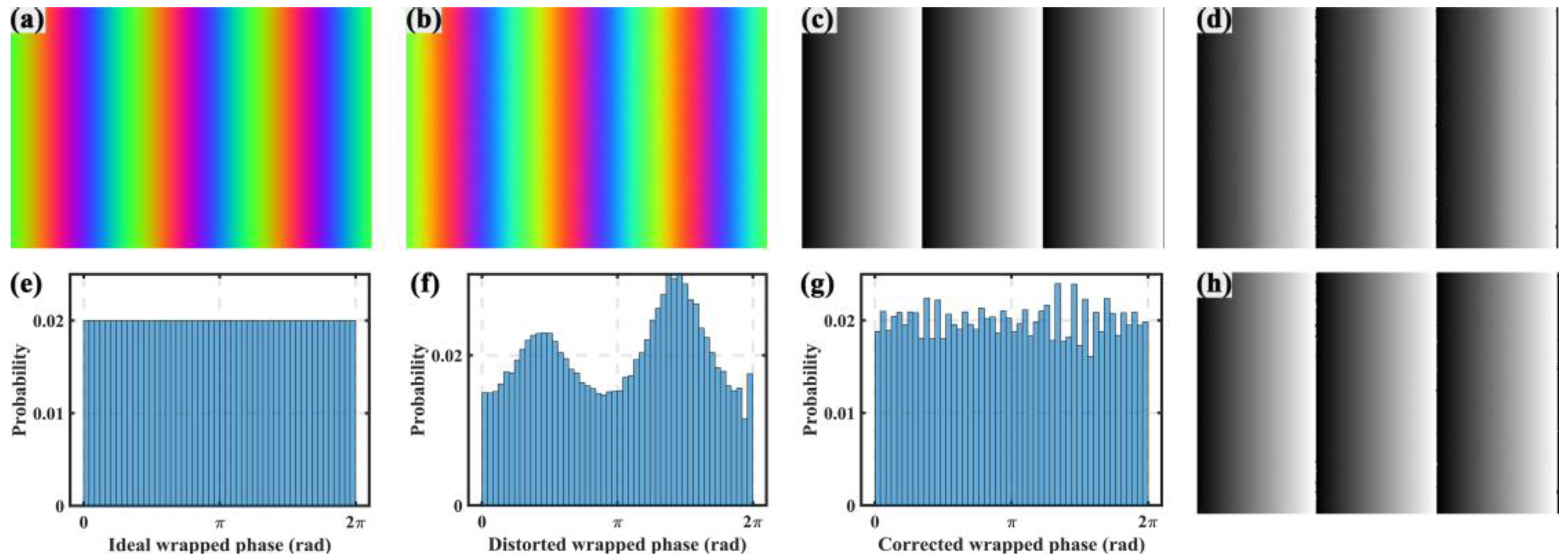
To simulate the random noises, Gaussian white noise with a zero mean and a standard deviation of 0.02 was added to the simulated patterns. In addition, to simulate the defocus blur, a Gaussian filter with a size of 5 × 5 pixels and a standard deviation of 2.0 was also applied to the simulated pattern. Figure 2b shows the distorted pattern with color crosstalk, random noises, and defocus blur. The wrapped phases of the ideal and distorted patterns were calculated separately with a three-step phase-shifting algorithm, as shown in Figure 2c,d. Clearly, the ideal phase presented excellent linearity in contrast to the distorted phase presenting significant nonlinearity. Then, the PPDs of the ideal and distorted phases were computed as illustrated in Figure 2e,f. Clearly, the PPD of the ideal phase was uniform; in contrast, the PPD of the distorted phase was very nonuniform. Finally, we applied the histeq MATLAB function with M = 50 on the distorted phase to adjust its PPD and correct the nonlinear error. Figure 2g illustrates the adjusted PPD, and Figure 2h shows the corrected phase. It is obvious that the adjusted PPD became much more uniform than the distorted PPD, but still with slight unevenness, to which the combination with random noises led. The corrected phase had very good linearity that was very approximate to the ideal phase. The minor residual error may be caused by the PPD unevenness and random noises. The simulation results demonstrated that the proposed method can effectively reduce the nonlinear error introduced by color crosstalk.
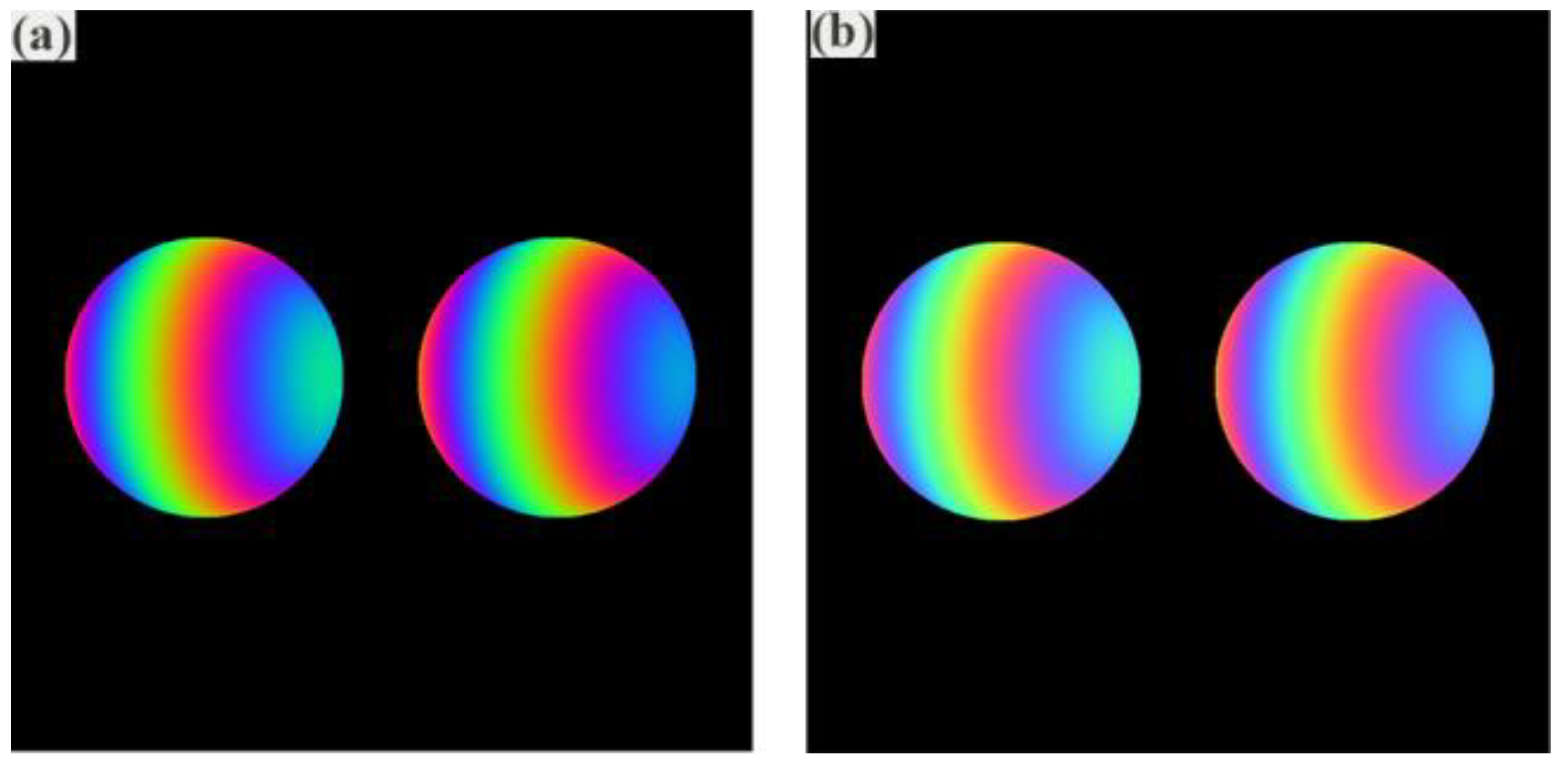
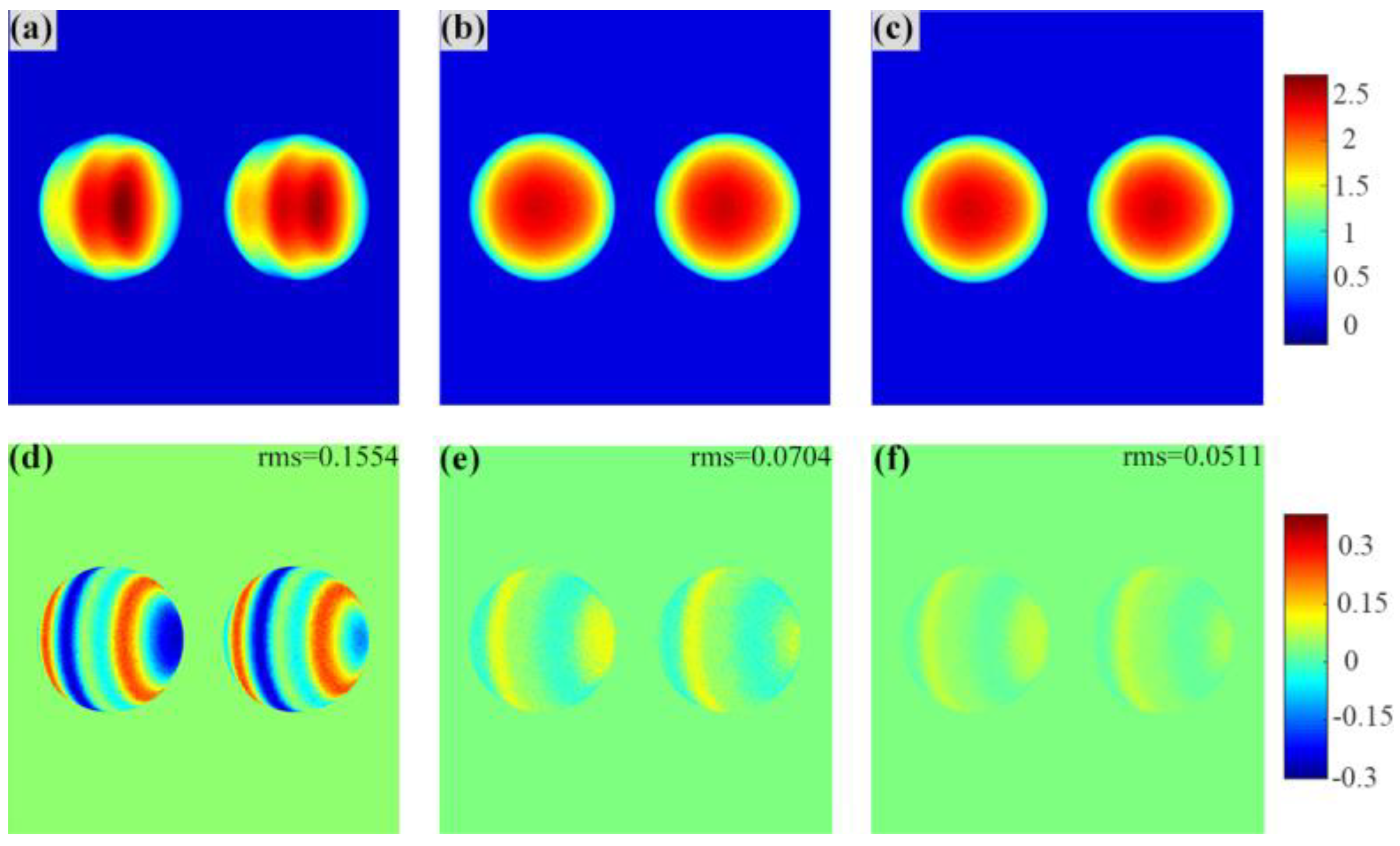
Different objects were considered in the following simulations. The resolution of the simulated images was 800 × 800 pixels, and other parameters remained unchanged. Two spheres, each with a radius of 150 pixels, were generated, and the distance between the two spheres was 100 pixels. The deformed images of the spheres by the ideal color pattern and the distorted color pattern are shown in Figure 3a and Figure 3b, respectively. Then, we recovered the absolute phase. Figure 4a shows the absolute phase retrieved from the distorted image without any corrections. To verify the necessity of spline fitting in the proposed method, we recovered the phase map using partial content of the proposed method, that is, the histogram equalization and the whole proposed method, respectively. Figure 4b shows the phase obtained utilizing only histogram equalization, and Figure 4c shows the phase recovered with the whole proposed method. The absolute phase obtained with the ideal image was regarded as the reference; thus, three error maps corresponding to Figure 4a–c, as shown in Figure 4d–f, were calculated. The root mean square (RMS) errors of the mentioned results were 0.1554 rad, 0.0704 rad, and 0.0511 rad, respectively. Obviously, the first step of the proposed method, the histogram equalization, was to correct the nonlinear error. However, the first step could induce a discretization error. To further improve the accuracy, the second step, a spline fitting algorithm, was presented to eliminate the discretization error. The error maps shown in Figure 4e–f conclude that the spline fitting algorithm was necessary in the proposed method, and the proposed method had a good performance for removing nonlinear errors.
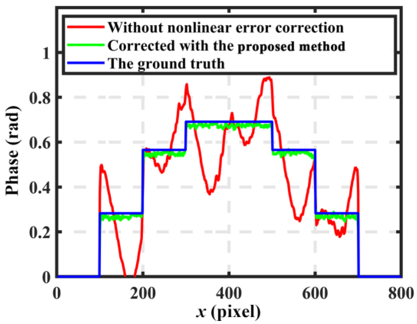
Secondly, a single, continuous, step height object was generated. The simulated parameters were the same as mentioned above. The necessity of spline fitting in our method was validated in the first simulation. In this simulation, the effectiveness of the proposed method in dealing with objects with cliff edges was verified. Similarly, we recovered the phase map using the normal unwrapped algorithm and the proposed method. Figure 5a shows the absolute phase obtained without nonlinear error elimination, and its surface had serious ripple errors. In contrast, the results recovered with the proposed method had smooth surfaces, as illustrated in Figure 5b. The ground truth of the step height is shown in Figure 5c. Figure 6 illustrates the cross-section of the recovered results and the ideal phase of the step height. The line marked in red is the distorted phase, and the information is unavailable for comparison to the ideal one. Apparently, nonlinear errors in the CPSP influenced the measuring results, and the surface information of the measured object was lost in errors. However, for the corrected one marked in green, the results were very close to the ideal one, and the surface was clearly presented. It can be seen from Figure 5 and Figure 6 that the proposed method guaranteed the measuring accuracy of CPSP.
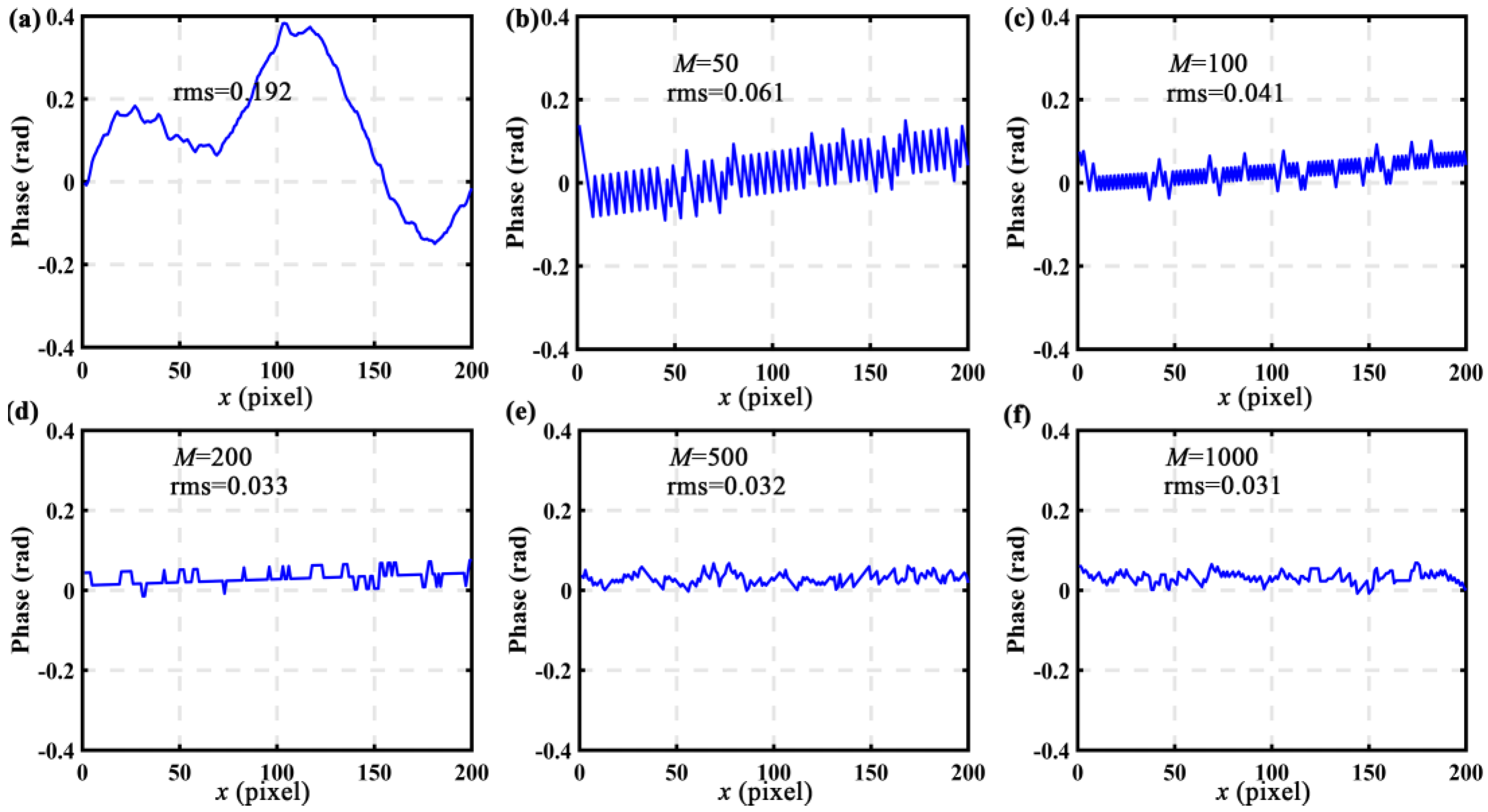
To explore the influence of the number M on the correction results, the residual errors under different M values were computed. Figure 7a illustrates the nonlinear error before PPD adjustment within one fringe period, and the RMS error was about 0.192 rad. Figure 7b–f illustrate the residual errors after PPD adjustment with different M values, and the corresponding RMS errors are also given. Further, Figure 8 plots the RMS error curve of the residual errors with respect to different M values ranging from 50 to 1000. In particular, the RMS residual error decreased to 0.061 rad when M = 50 , 0.041 rad when M = 100 , 0.033 rad when M = 200 , 0.032 rad when M = 500 , and 0.031 rad when M = 1000 . It is obvious that the RMS residual error was inversely proportional to M . If M 500 , the RMS residual error degraded quickly from 0.061 to 0.032 rad with the increase of M . If M > 500 , the RMS residual error stayed stable with the increase of M , only having a variation of 0.001 rad. The simulation results confirmed that the residual error can be restrained by choosing a relatively larger M value. However, a larger M value always requires higher computation cost; thus, M = 500 was selected in the following experiments.

4. Experiments

A typical FPP system consisting of a digital-light-processing (DLP) projector and a complementary metal oxide semiconductor (CMOS) camera was built. The DLP projector was a Light-Crafter 4500 with a resolution of 912 × 1140 pixels. The camera was a Basler a2A1920-160ucBAS with a resolution of 1920 × 1200 pixels. The objects were perpendicular to the camera at a distance of 60 cm. The color-encoded fringes were sequentially projected onto the measured objects using the projector, and the camera simultaneously captured the deformed images. The pitch of the stripe was 18 pixels. The wrapped phase was recovered with the three-step phase-shift algorithm [24].
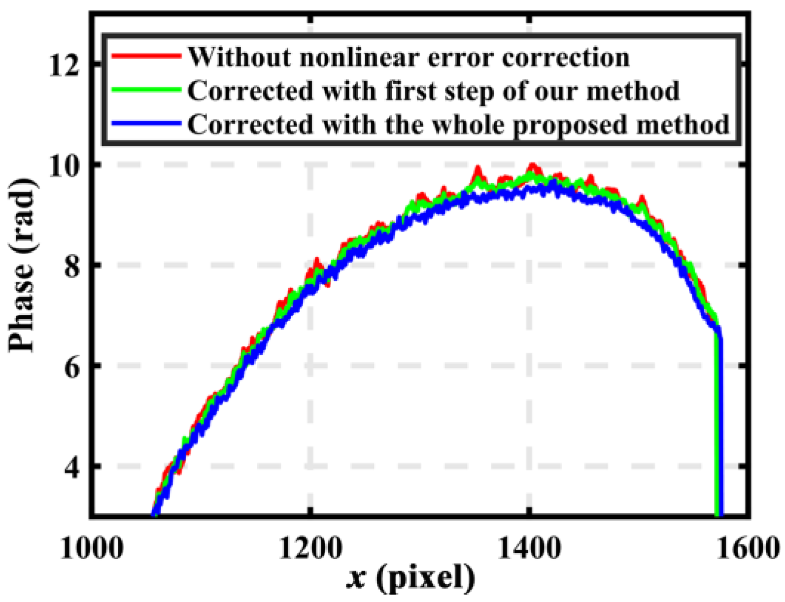
To validate the performance of the proposed method, a sculpture with a simple surface was measured first. The captured image is shown in Figure 9a. Its corresponding wrapped phase was calculated using the three-step phase-shift algorithm, and its absolute phase was obtained utilizing the multifrequency method. The reconstruction results are shown in Figure 9b. Obviously, severe ripple errors induced by crosstalk occurred on the surface. To validate the necessity of spline fitting in a real-world scenario, we also recovered the surface with only the first step of the proposed method, and the results are shown in Figure 9c. The final result obtained with the whole proposed method is illustrated in Figure 9d. As it can be seen in Figure 9b–d, the result obtained with the first step of the proposed method had some slight ripple errors, and the nonlinearity errors were effectively eliminated in comparison to the distorted one. Moreover, compared with the former two results, there were almost no errors on the surface that was recovered by the whole proposed method. We concluded, the same as the results obtained in the simulation, that spline fitting is necessary and effective in our method. For the sake of clarity, Figure 10 illustrates the cross-section of the recovered results of the sculpture. Obviously, the final result was smoother than both the distorted result and the result obtained with the first step of the proposed method. It is important to point out that the proposed method capably corrected the nonlinear errors, and the two steps of the method were indispensable.
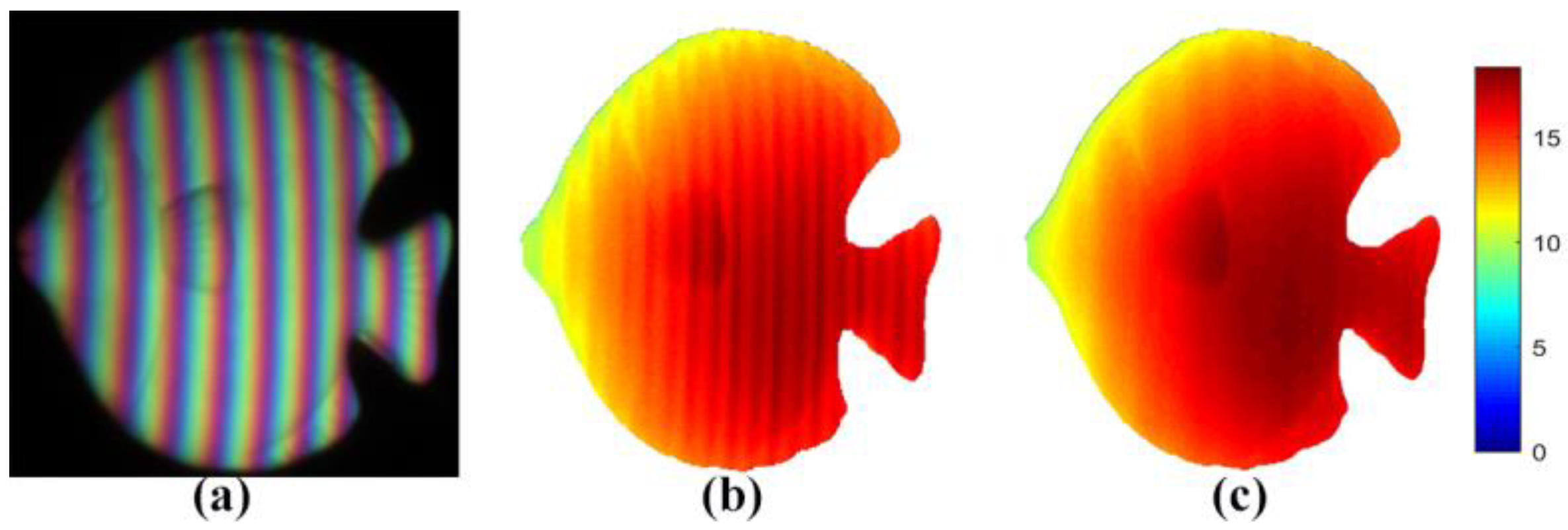
In the next experiment, we measured a white fish with slightly complex surfaces. Figure 11a shows the deformed image of the fish. For normal multifrequency unwrapped algorithms, the recovered absolute phase had obvious errors, as shown in Figure 11b. The results illustrated in Figure 11c obtained with our proposed method had smooth surfaces. Experiments in a real-world scenario showed that the proposed method could improve the measurement effectiveness of CPSP and could be utilized for more color-encoded fringe-based applications.

5. Discussions and Conclusions

The accuracy of color phase-shifting profilometry (CPSP) is limited because of nonlinear errors caused by color coupling [25]. This paper proposed a simple and efficient method based on histogram equalization to address this issue. Compared with Refs. [12,13,14], the proposed method did not require any precalibrated operations to obtain the relationship between the distorted pixels and the ideal ones. Compared with Ref. [16], the proposed method did not need any extra images to obtain more distorted information for correction. Although the proposed method possesses the aforementioned advantages, it has its own limitations. The proposed method corrected the nonlinear errors based on histogram equalization, and its accuracy hinged on the amount of data at a certain degree. The larger the number of data, the higher the accuracy. Moreover, this limitation can be addressed by using a phase-shifted wrapped phase [26]. Overall, the proposed method accurately enhanced the measurement speed of CPSP.
An effective method was presented in this paper for color crosstalk correction. The proposed method contained two main steps. The first was to correct the crosstalk using histogram equalization. Second, a spline fitting algorithm was implemented to remove the discretization error induced by the histogram equalization operation. Obviously, compared with other compensation methods, the proposed approach did not require any precalibration information or additional patterns and simplified the correction without a loss of efficiency. The simulations and experiments clearly showed that this proposed method efficiently solved the nonlinear error problem. The proposed method expands applications of CPSP. Meanwhile, the proposed method provides a hint about how to eliminate errors using the characteristics of fringes on one hand. On the other hand, it provides a clue to correct errors in other scenarios (e.g., dynamic errors, etc.) with histogram equalization.
Author Contributions

Conceptualization, B.C. and L.L.; methodology, B.C.; software, B.C.; validation, H.Z. and C.T.; formal analysis, H.Z.; investigation, C.T.; resources, H.Z.; data curation, H.Z.; writing—original draft preparation, B.C.; writing—review and editing, L.L.; visualization, B.C.; supervision, L.L.; project administration, L.L.; funding acquisition, B.C. and L.L. All authors have read and agreed to the published version of the manuscript.

Funding

This work was supported by the National Natural Science Foundation of China (52105538), the Open Fund of Key Laboratory of Icing and Anti/De-icing (Grant No. IADL20200308), and the Key R&D Program of Anhui Province (202004h07020009).

Institutional Review Board Statement

Not applicable.

Informed Consent Statement

Not applicable.

Data Availability Statement

Not applicable.

Conflicts of Interest

The authors declare no conflict of interest.

References

  1. Xu, J.; Zhang, S. Status, challenges, and future perspectives of fringe projection profilometry. Opt. Laser Eng. 2020, 135, 106193. [Google Scholar] [CrossRef]
  2. Zuo, C.; Feng, S.; Huang, L.; Tao, T.; Yin, W.; Chen, Q. Phase shifting algorithms for fringe projection profilometry: A review. Opt. Laser Eng. 2018, 109, 23–59. [Google Scholar] [CrossRef]
  3. Cheng, N.-J.; Su, W.-H. Phase-Shifting Projected Fringe Profilometry Using Binary-Encoded Patterns. Photonics 2021, 8, 362. [Google Scholar] [CrossRef]
  4. Lu, L.; Suresh, V.; Zheng, Y.; Wang, Y.; Xi, J.; Li, B. Motion induced error reduction methods for phase shifting profilometry: A review. Opt. Laser Eng. 2021, 141, 106573. [Google Scholar] [CrossRef]
  5. Chen, R.; Xu, J.; Zhang, S. Comparative study on 3D optical sensors for short range applications. Opt. Laser Eng. 2022, 149, 106763. [Google Scholar] [CrossRef]
  6. Heist, S.; Zhang, C.; Reichwald, K.; Kuhmstedt, P.; Notni, G.; Tunnermann, A. 5D hyperspectral imaging: Fast and accurate measurement of surface shape and spectral characteristics using structured light. Opt. Express 2018, 26, 23366–23379. [Google Scholar] [CrossRef]
  7. Cai, B.; Yang, Y.; Wu, J.; Wang, Y.; Wang, M.; Chen, X.; Wang, K.; Zhang, L. An improved gray-level coding method for absolute phase measurement based on half-period correction. Opt. Lasers Eng. 2020, 128, 106012. [Google Scholar] [CrossRef]
  8. Tornero-Martinez, N.; Trujillo-Schiaffino, G.; Anguiano-Morales, M.; Mendoza-Villegas, P.G.; Salas-Peimbert, D.P.; Corral-Martínez, L.F. Color profilometry techniques: A review. Measurement 2006, 45, 0136021. [Google Scholar] [CrossRef]
  9. Zhang, Z.; Xu, Y.; Liu, Y. Crosstalk reduction of a color fringe projection system based on multi-frequency heterodyne principle. In Proceedings of the 2013 International Conference on Optical Instruments and Technology: Optoelectronic Measurement Technology and Systems, Beijing, China, 19 December 2013. [Google Scholar]
  10. Su, W. Color-encoded fringe projection for 3D shape measurements. Opt. Express 2007, 15, 13167–13181. [Google Scholar] [CrossRef]
  11. Towers, Z.; Zhang, C.; Towers, D. Phase and colour calculation in colour fringe projection. J. Opt. A Pure Appl. Opt. 2007, 9, S81–S86. [Google Scholar]
  12. Kinell, L. Multichannel method for absolute shape measurement using projected fringes. Opt. Lasers Eng. 2004, 41, 57–71. [Google Scholar] [CrossRef]
  13. Huang, P.S.; Hu, Q.; Jin, F.; Chiang, F.P. Color-encoded digital fringe projection technique for high-speed three-dimensional surface contouring. Opt. Eng. 1999, 38, 1065–1071. [Google Scholar] [CrossRef]
  14. Zhang, Z.H.; Towers, C.E.; Towers, D.P. Time efficient color fringe projection system for 3D shape and color using optimum 3-frequency selection. Opt. Express. 2006, 14, 6444. [Google Scholar] [CrossRef]
  15. Wan, Y.; Cao, Y.; Chen, C.; Wang, Y.; Fu, G.; Wang, L.; Li, C. Active phase error suppression for color phase-shifting fringe projection based on hue pre-correction. Opt. Laser Technol. 2019, 118, 102–108. [Google Scholar] [CrossRef]
  16. Wu, M.; Wu, G.; Zhang, S.; Wu, Y.; Liu, F.; Fan, N. Point-to-point compensation method for color coupling and imbalance in color-fringe pattern profilometry. J. Opt. 2020, 22, 095702. [Google Scholar] [CrossRef]
  17. Hu, Y.; Xi, J.; Chicharo, J.; Yang, Z. Blind color isolation for color-channel-based fringe pattern profilometry using digital projection. J. Opt. Soc. Am. A 2007, 24, 2372–2382. [Google Scholar] [CrossRef]
  18. Ma, S.; Zhu, R.; Quan, C.; Li, B.; Tay, C.; Chen, L. Blind phase error suppression for color-encoded digital fringe projection profilometry. Opt. Commun. 2012, 285, 1662–1668. [Google Scholar] [CrossRef]
  19. Flores, J.L.; Muñoz, A.; Ordoñes, S.; Garcia-Torales, G.; Ferrari, J.A. Color-fringe pattern profilometry using an efficient iterative algorithm. Opt. Commun. 2017, 391, 88–93. [Google Scholar] [CrossRef]
  20. Wang, Y.; Liu, L.; Wu, J.; Chen, X.; Wang, Y. Hilbert transform-based crosstalk compensation for color fringe projection profilometry. Opt. Lett. 2020, 45, 2199–2202. [Google Scholar] [CrossRef]
  21. Ayubi, G.A.; Martino, J.; Alonso, J.; Fern´andez, A.; Flores, J.; Ferrari, A. A Color encoding of binary fringes for gamma correction in 3-D profiling. Opt. Lett. 2012, 37, 1325–1327. [Google Scholar] [CrossRef]
  22. Pan, J.; Huang, P.S.; Chiang, F.P. Color phase-shifting technique for three-dimensional shape measurement. Opt. Eng. 2006, 45, 013602. [Google Scholar]
  23. Caspi, D.; Kiryati, N. Range imaging with adaptive color structured light. IEEE Trans. Pattern Anal. Mach. Intell. 1998, 20, 470–480. [Google Scholar] [CrossRef]
  24. Huang, P.S.; Zhang, S. Fast three-step phase-shifting algorithm. Appl. Opt. 2006, 45, 5086–5091. [Google Scholar] [CrossRef]
  25. Skydan, O.; Lalor, M.; Burton, D. Using coloured structured light in 3-D surface measurement. Opt. Lasers Eng. 2005, 43, 801–814. [Google Scholar] [CrossRef]
  26. Deng, J.; Li, J.; Feng, H.; Zeng, Z. Flexible depth segmentation method using phase-shifted wrapped phase sequences. Opt. Lasers Eng. 2019, 122, 284–293. [Google Scholar] [CrossRef]
Figure 1. Results regarding different patterns. (a,b) Intensity distributions of ideal patterns and distorted patterns, respectively; (c) wrapped phases of the ideal pattern and the distorted pattern; (d) absolute phases of the ideal pattern and the distorted pattern; (e) nonlinear error distribution; and (f) phase probability distribution of the ideal and the distorted patterns.
Photonics 09 00385 g001
Figure 2. Simulated data: (a) ideal pattern; (b) distorted pattern; (c) ideal phase; (d) distorted phase; (e) ideal PPD; (f) distorted PPD; (g) adjusted PPD with M = 50; and (h) corrected phase.
Photonics 09 00385 g002
Figure 3. Spheres deformed by (a) the ideal pattern and (b) the distorted pattern.
Photonics 09 00385 g003
Figure 4. Results of the simulated spheres: (a) absolute phases recovered without corrections; (b) phase map obtained only with the histogram equalization; (c) phase map obtained with the whole proposed method; and (df) error maps corresponding to (ac), respectively. Unit: rad.
Photonics 09 00385 g004
Figure 5. Results of the simulated step heights. (a) absolute phase recovered without corrections; (b) absolute phase corrected with the proposed method; and (c) the ground truth of the simulated object. Unit: rad.
Photonics 09 00385 g005
Figure 6. Cross-sections of the recovered and ideal absolute phases.
Photonics 09 00385 g006
Figure 7. Cross-sections of different phase errors within one fringe period: (a) nonlinear errors before PPD adjustment and residual errors after PPD adjustment with (b) M = 50 , (c) M = 100 , (d) M = 200 , (e) M = 500 , and (f) M = 1000 .
Photonics 09 00385 g007
Figure 8. RMS residual errors under different M values.
Photonics 09 00385 g008
Figure 9. Results of a white sculpture: (a) captured image of the sculpture; (b) the absolute phase without corrections; (c) the absolute phase obtained using the first step of the proposed method; and (d) the absolute phase optimized with the whole proposed method. Unit: rad.
Photonics 09 00385 g009
Figure 10. One cross-section of the recovered absolute phases of the sculpture.
Photonics 09 00385 g010
Figure 11. Results of a white fish: (a) captured image of the fish; (b) the absolute phase without corrections; and (c) the absolute phase obtained the proposed method. Unit: rad.
Photonics 09 00385 g011
Publisher’s Note: MDPI stays neutral with regard to jurisdictional claims in published maps and institutional affiliations.