1. Introduction
We consider two sources of the distortions of the light coming to the high-resolution Echelle spectrograph: the behavior of the telescope itself (its instability) and the aberrations caused by atmospheric turbulence [
1]. A corrector to control for the position of the center of a star image has been developed and is being used at the entrance to the NES high-resolution spectrograph [
2]. The statistics of the deviations of the position of the image center of a star have been collected for various atmospheric parameters in the surface layer (temperature, wind speed, etc.). From the practical experience of observations and statistics, it turned out that the tilts (Zernike 1 and Zernike 2) of the input beam with a diameter of 6 m are characterized by a low-frequency spectrum, with maximum deviations in the position of a star depending on the image quality.
Quasi-periodic fluctuations of the position of a star on the spectrograph slit were detected during the first observations at the Nasmyth foci of the 6 m telescope. At the very beginning, we believed that those fluctuations were caused by the restless behavior of the astronomer, who was on the moving platform of the Nasmyth focus, but this was proved to be false. It was also found that the excessively frequent correction of the position of the star through the telescope’s driving system could lead to slowly damped oscillations or even rock the telescope. The relationship between the nature of fluctuations and the speed and duration of a single act of correction was also revealed. The effect of slowly damped oscillations on the position of a star was also discovered as a result of short-term wind gusts (up to a speed of several m/s). At the minimum speed of the correction of the movement of the telescope, oscillations occurred, with an amplitude of up to 1″, and the damping time of the oscillations was 25 s. As the correction speed increased, the effect became stronger. It was concluded that, to keep the center of the star image at the center of the spectrograph slit, it was optimal to use a local corrector, which would eliminate the need to correct the overall tilt of the telescope at high (for a telescope) frequencies.
It is already an established practice in astronomy to use an image-stabilization system [
3,
4,
5,
6,
7,
8]. For example, a fast-steering mirror was produced and designed to correct for the image stabilization of the astronomical telescopes [
3]; this work describes the optimization process of mirror development and the system performance. Another approach, when one piezo-driven tip-tilt mirror was used to minimize the motions of the solar optical telescope images with a frequency above 14 Hz to improve polarimetric measurements, is described in [
4]. A tip-tilt controller for the Solar Orbiter is discussed in [
5]. A control algorithm was developed by the authors as well [
6]. An image-stabilization system was described recently [
7] by Chinese scientists. They presented both simulations and experiments on testing the accuracy of the image-stabilization system of a space telescope. The influence of the vibration isolation platform was also considered. Moreover, there are a number of works that are not related directly to astronomy but are of particular interest for beam stabilization [
9,
10].
This paper discusses a system for active laser beam stabilization based on an FPGA [
11]. The system is a part of a closed-loop adaptive optical system to improve the efficiency of high-resolution spectroscopy on the 6 m telescope BTA [
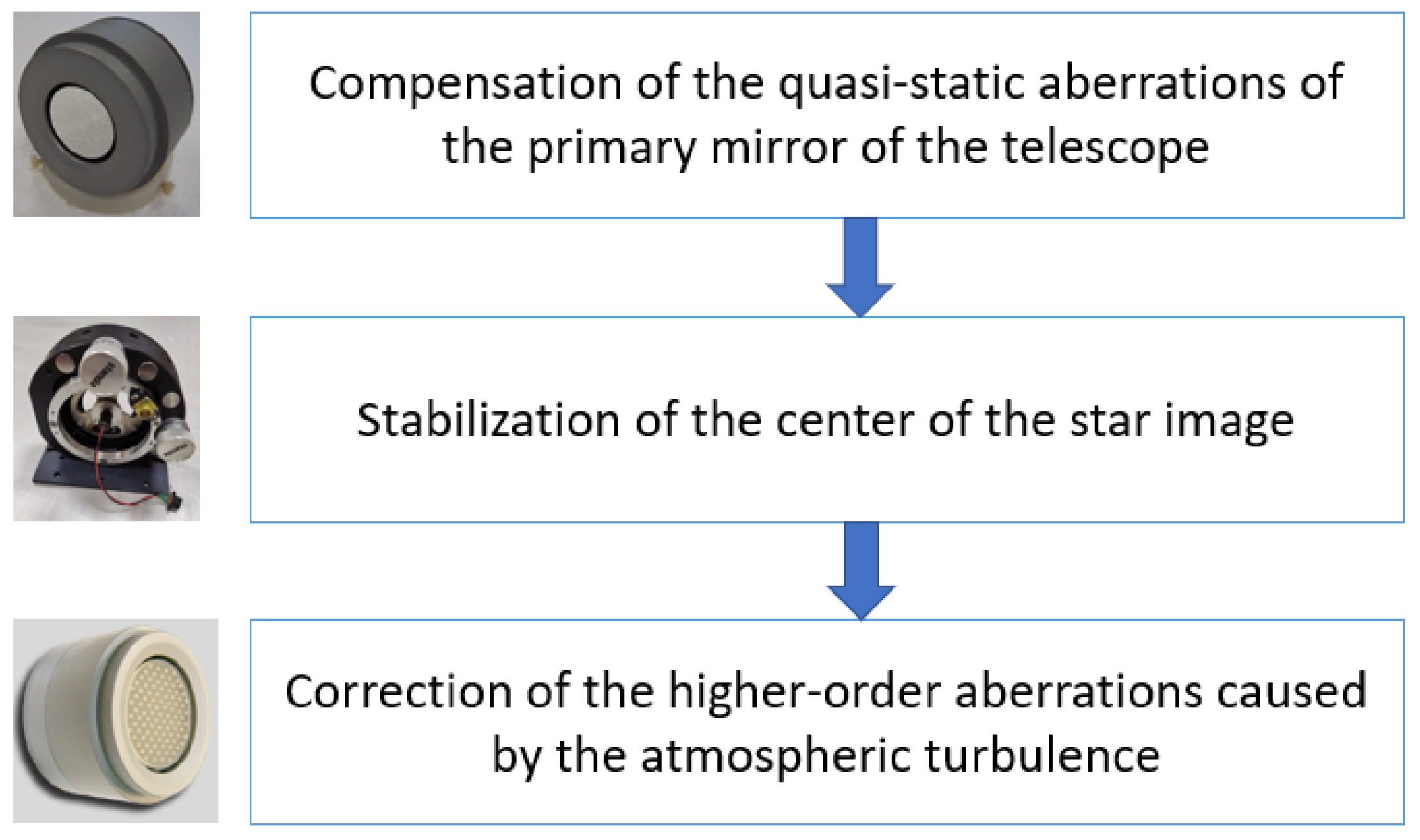
12]. The structure of the overall adaptive system for the telescope is presented in
Figure 1. Each part is used for a certain purpose: some mirrors serve to compensate for large-scale slowly changing aberrations, while other mirrors compensate for small-scale aberrations that occur when passing through a turbulent atmosphere, and some mirrors are used to stabilize the position of the beam. We expect the whole adaptive system to decrease a star image on the spectrograph slit from 1 arcsec to 0.2 arcsec.
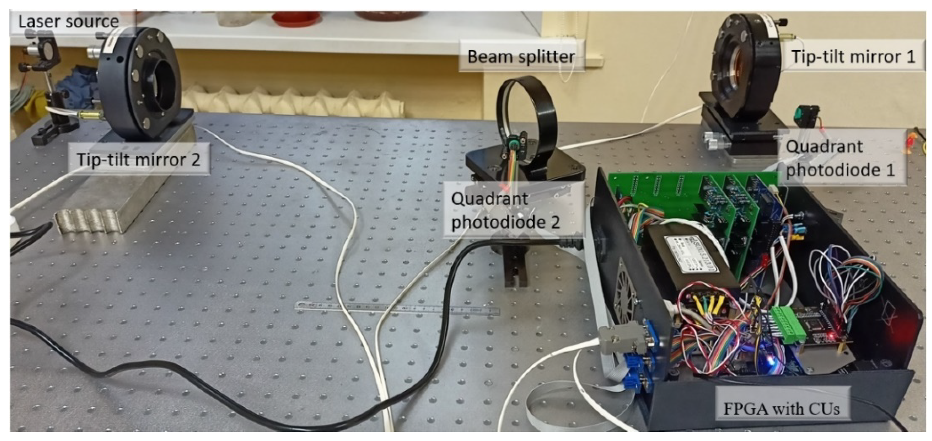
At the initial stage of our work, we analyzed the structure of the aberrations in terms of Zernike polynomials and the typical amplitudes of Zernike coefficients measured in our laboratory setup [
13]. Experiments showed that the contribution of the tilts is essential, so the beam position should be separately controlled during the wavefront correction of a beam distorted by the atmospheric turbulence. The experimental setup consisted of two tip-tilt mirrors, two control units to apply voltages to the piezo drivers, and two quadrant photodiodes to detect the beam position jitter. The first mirror is needed to set the beam to the desired point, and the second one facilitates directing the beam along the optical axis. The use of the FPGA allows the combination of all the electronics in one box, and the main goal of the FPGA is to reduce calculation time so that the tip-tilt correctors become the main limiting element of the system. The FPGA collects data from the quadrant photodiodes, analyzes the data, and calculates and applies voltages to the tip-tilt mirror’s drivers. A scheme of a digital control module and its interaction with the tip-tilt mirrors and control units is elaborated. To confirm the ability of the beam stabilization, a series of experiments were carried out.
2. Atmospheric Turbulence Input
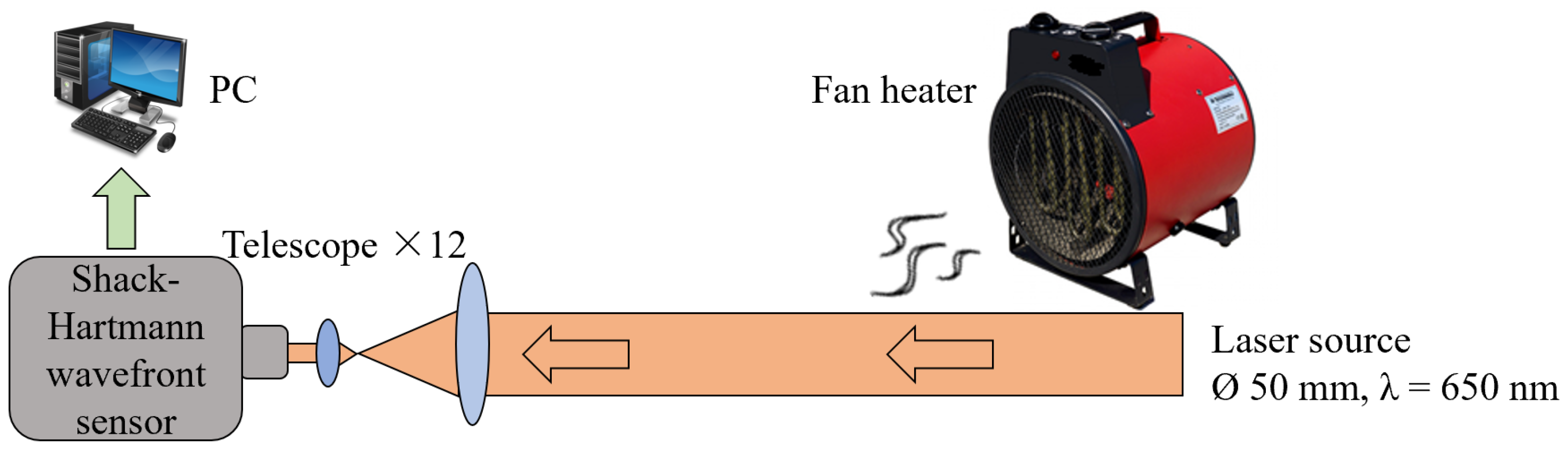
To analyze the input of the atmospheric turbulence, we used a setup based on a self-made Shack–Hartmann wavefront sensor [
14,
15,
16,
17,
18]. A laser beam wavefront is distorted by the airflow made by a 1.5 kW fan heater with a diameter of 200 mm. The aberrations caused by the fan heater are then analyzed with a high-speed Shack–Hartmann wavefront sensor (
Figure 2) [
19]. The image resolution is 480 × 480, and the microlenses array has 20 × 20 lenses with a focal length of 12 mm and a size of 240 µ × 240 µ each. A laser diode (LDS-655-FP-1.5 by Laserscom) with a wavelength of 650 nm coupled to an optical fiber is collimated up to a diameter of 50 mm. The data is obtained with a frequency of 2000 Hz. To reconstruct the wavefront, a modal method is used [
20,
21]. More information on the experiment is presented in [
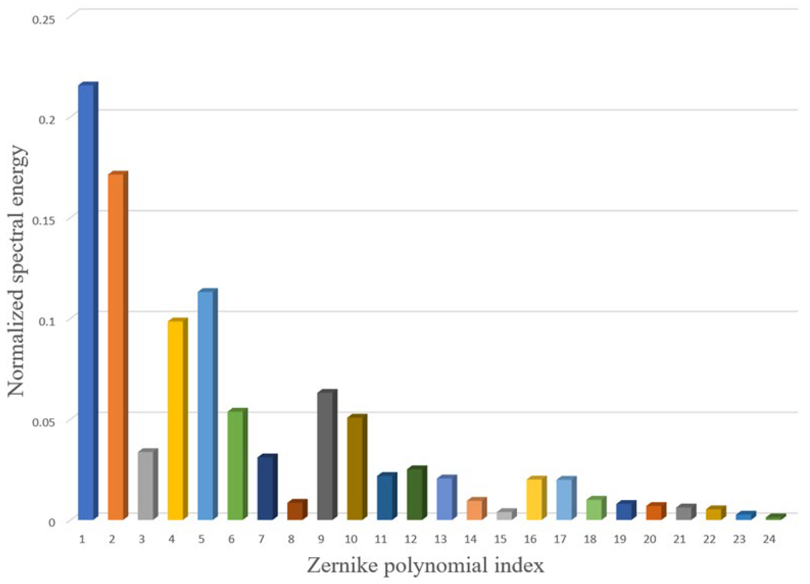
13]. The spectral energy distribution over Zernike polynomials is presented in
Figure 3. This picture confirms that not only the tilts have to be corrected but also that higher-order aberrations have sufficient input. Thus, the use of the tip-tilt correction system is only the first step, and higher-order adaptive optics should be used [
22] when the tilts are compensated. The tilts (Zernike 1 and Zernike 2) have the largest amplitude among the distortions caused by the atmospheric turbulence [
23].
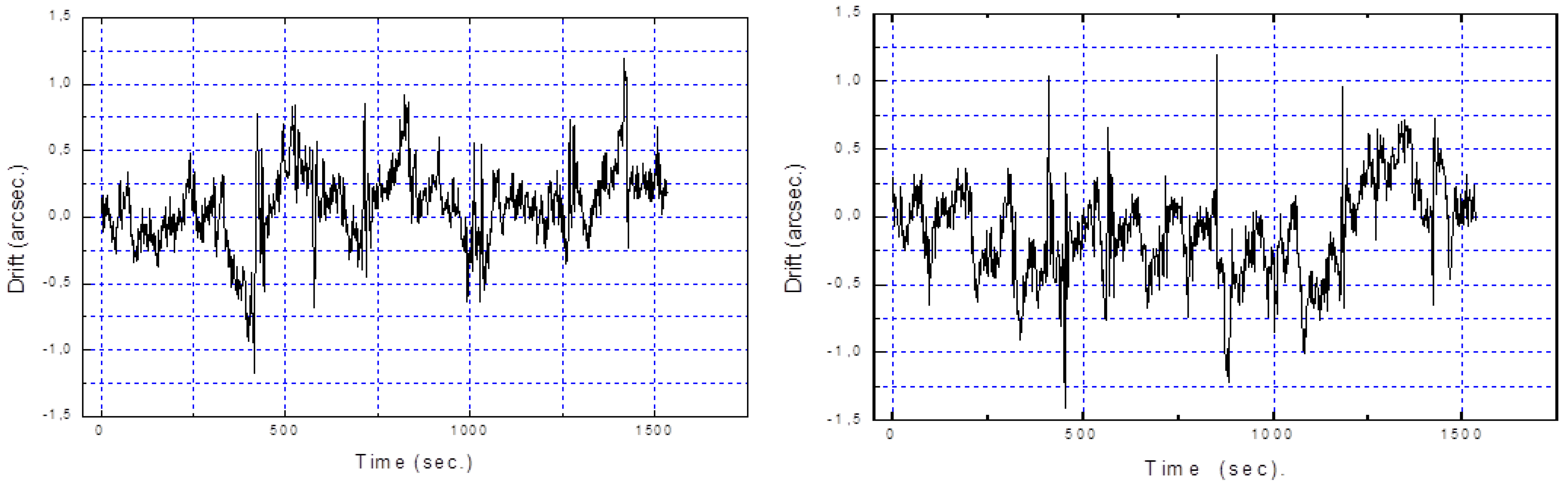
The displacements of the center of the star image in front of the spectrograph of the 6 m telescope were also measured, and results are presented in
Figure 4. The fluctuations are caused not only by the turbulence but also by the fundamental frequency of the telescope, the non-ideal position of the axes, mechanical deformations, and the wind inside the telescope dome. The center of the image fluctuates with a typical amplitude of ±1 arcsec. As the spectrograph slit is just about 0.7 arcsec, these fluctuations of the image lead to 80% loss of the incoming light. If the light is stabilized with an accuracy of ±0.1–0.2 arcsec, it allows an increase in the spectrograph transmission up to 2.5 times, which is equivalent to one order of magnitude gain in angular resolution.
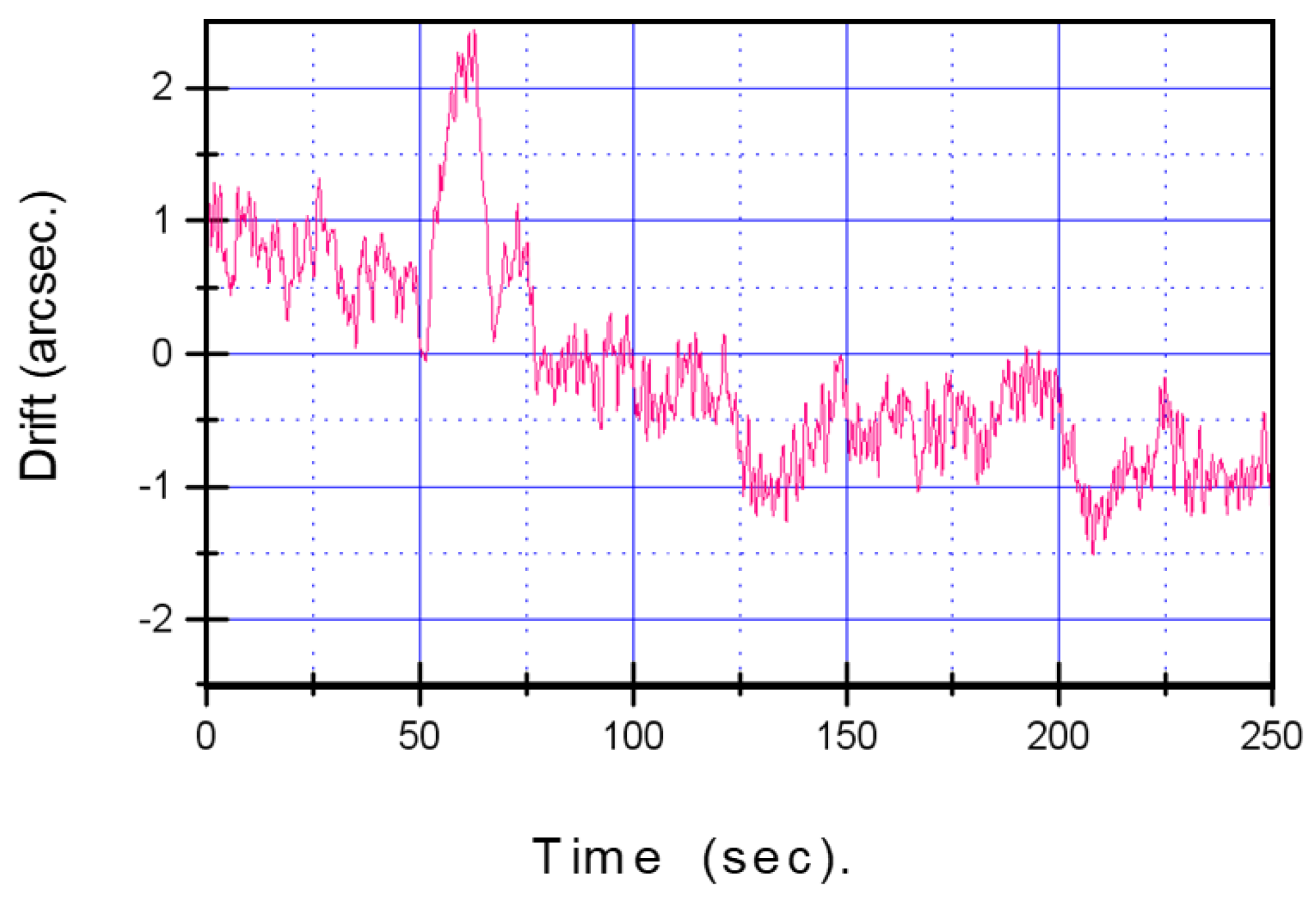
When the weather conditions are bad and the wind is strong, the amplitude of the fluctuations of the position of a star image increases (
Figure 5). Here we can also visualize the total drift of the star image over tens of seconds.
3. FPGA-Based Light Position Stabilization
3.1. Tip-Tilt Mirror Structure
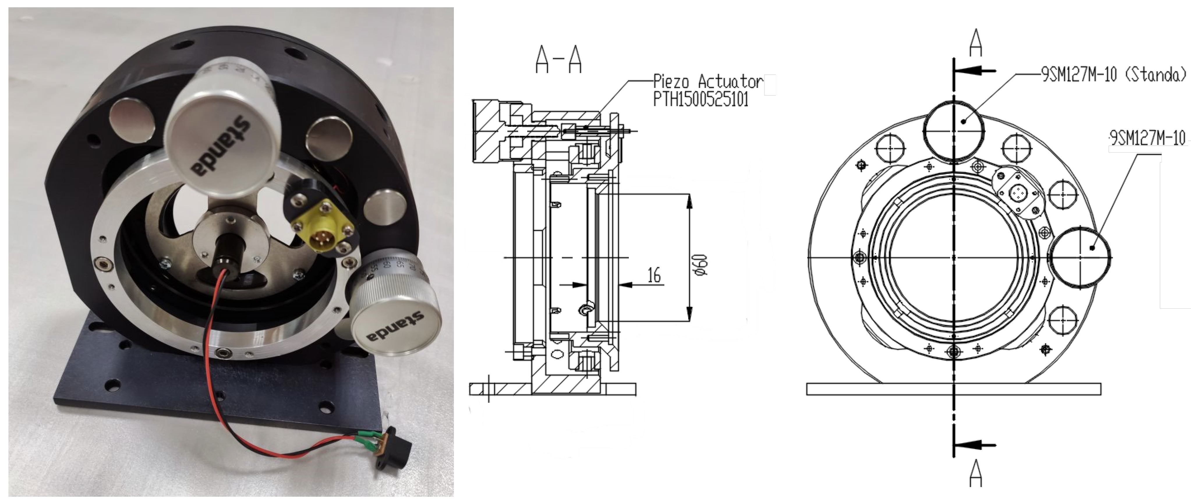
To stabilize the beam position, two tip-tilt mirrors controlled with an FPGA board were used. The tilts of the mirrors were ensured by piezoceramic elements with a capacity of 1 mF. The diameter of the mirror was 60 mm. The first resonance frequency of the mirror was found at 615 Hz. The mirror could be controlled with a frequency up to 500 Hz. The full dynamic range for the tilt correction was equal to 200 µrad, with a resolution of 0.05 µrad. A photo of the mirror and a cross-section together with the back view are shown in
Figure 6. The piezoceramic elements (Ring Multilayer Piezo Actuators PTH1500525101 by Suzhou Pant Piezoelectric Tech. Co) were combined with the adjustment screws (9SM127M-10 by Standa).
3.2. Beam Stabilization Setup
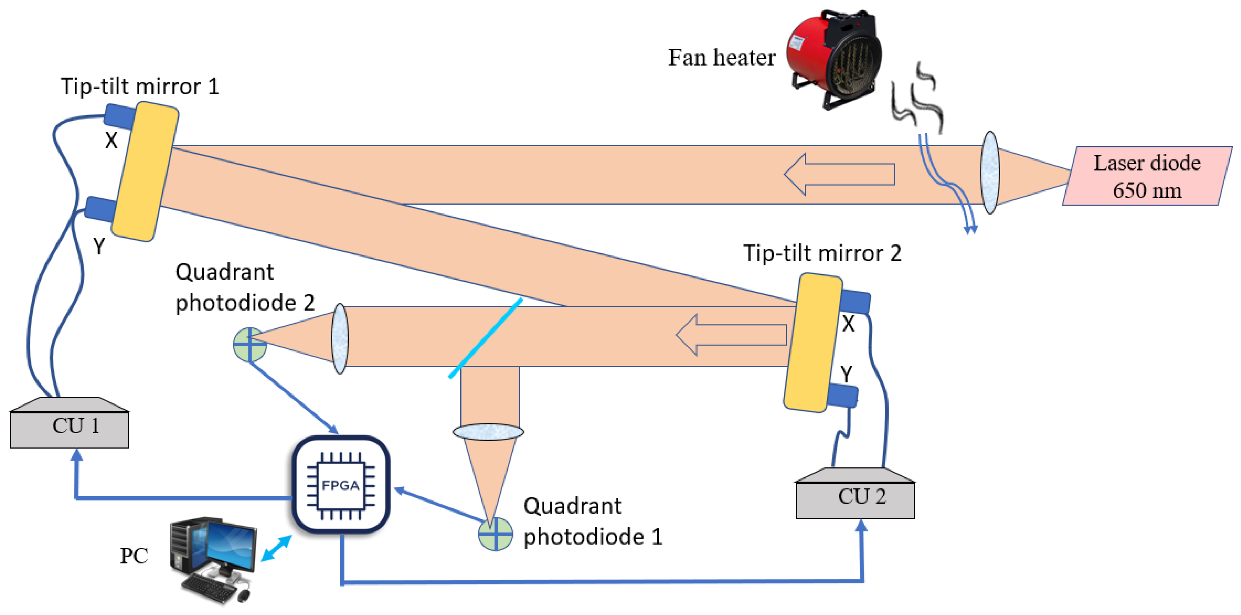
The setup to investigate the efficiency of the work of the beam-stabilization system is presented in
Figure 7. The 50 mm laser beam distorted by a fan heater reflected from two tip-tilt mirrors, and the center of the beam was then detected with two quadrant photodiodes with a diameter of 10.2 mm, each placed at different distances from the light source (25 cm in our case). The data from the photodiodes was collected by the FPGA, and then the voltages to be applied to the piezo drivers of the mirrors to correct for the beam displacement were calculated. The FPGA sent commands to the control units (CU 1, CU 2) to change the voltages on the piezo drivers of the mirrors. Control units allow the application of voltages from −30 V to 190 V. We used a PC to adjust the system before the correction was started, to measure the response functions of each tip-tilt mirror, and to save the resulting data in an appropriate format.
3.3. FPGA Implementation
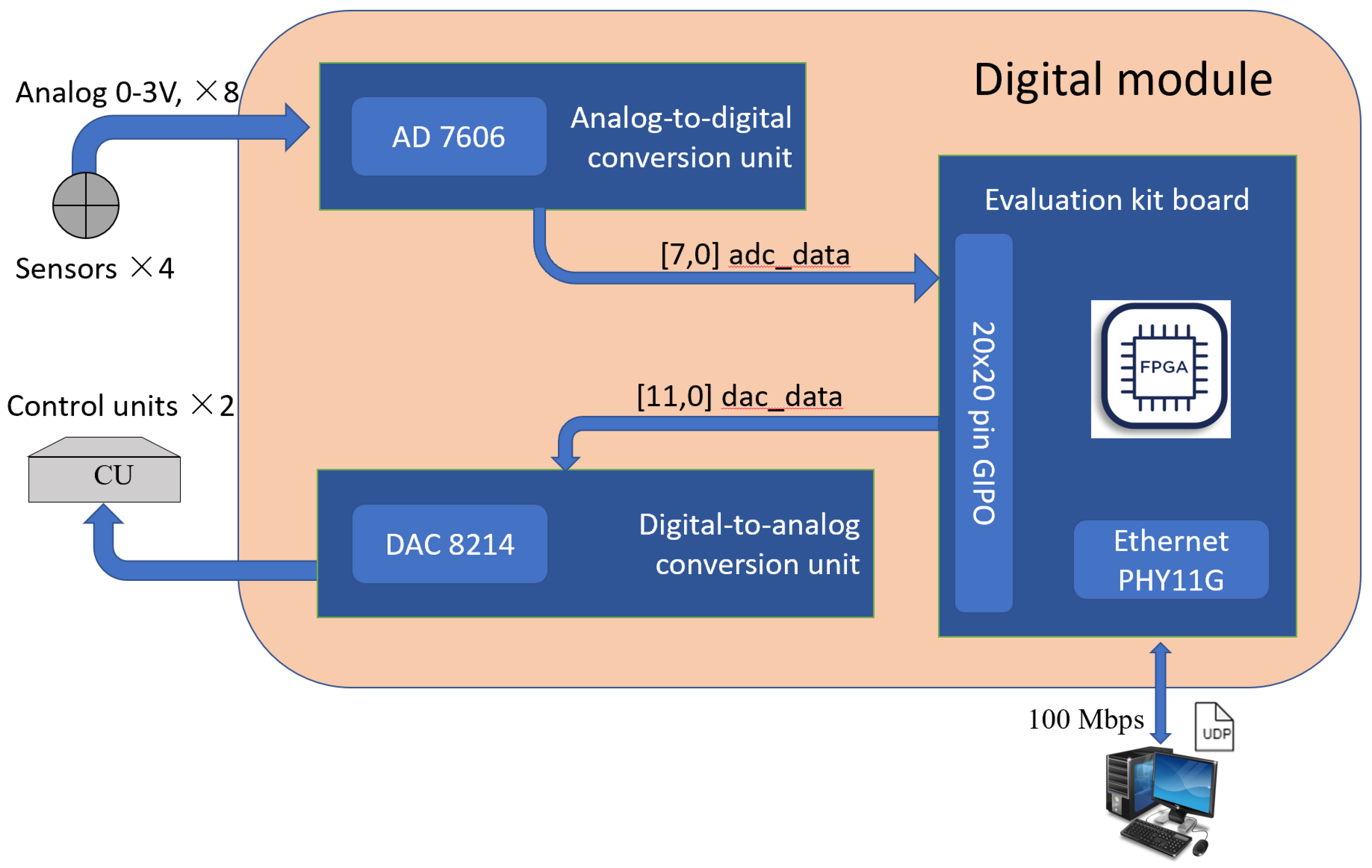
The FPGA was placed on a printed board to make one digital module connected with the external modules to digitize the voltages from the photodiodes, to calculate the voltages for the tip-tilt drivers, to make a digital-to-analog conversion of the voltages, and also to synchronize the entire system. The board consisted of the following parts (
Figure 8):
An analog-to-digital conversion unit to receive the voltages from the quadrant photodiodes;
Unit for calculating digital values of corrective voltages;
Unit for digital-to-analog conversion.
Each unit was placed on its own PC board. The elements were connected by a digital channel with the LVCMOS 2.5 V interface. The Cyclone 10 LP FPGA Evolution Kit board FPGA Intel® Cyclone® 10CL025YU256 was used as a unit to calculate the value of the voltages for piezo drivers.
The FPGA configuration was developed in the Quartus Prime 18.0 CAD environment from Intel. The configuration consists of 4 main modules:
Control and communication module with an analog-to-digital conversion (ADC) unit
Control and communication module with a digital-to-analog conversion (DAC) unit
Module for receiving and sending data to the control program installed on the PC via the UDP protocol
Control module for the operation of the block for calculating digital values of the corrective voltages
The control and communication module with an analog-to-digital conversion unit had eight channels for converting an analog signal into a digital code. It also facilitated working with 1-bit, 8-bit, and 16-bit data buses. In the described system, due to the limited size of the connector, the mode with an 8-bit data bus was used. The module controlled the operation of the chip, receiving and buffering data.
The control and communication module with the digital-to-analog conversion unit provided sequential loading of the values into each channel of the DAC chip in double-buffering mode for the simultaneous setting of the voltages in all analog channels of the chip.
The communication module contained internal registers to interact with the control module for calculating digital values of the voltages. The operation of the module was independent of the main operation cycle of the tip-tilt system.
The control module analyzed the state of the control registers of the communication module with the control program. Upon detection of the value corresponding to the start of the work cycle, the module performed the following actions:
Sent a start command to the control and communication module with the analog-to-digital converter;
Wrote registers with the data, on command from the analog-to-digital conversion unit;
Calculated voltages values;
Sent a command to the control and communication module with a digital-to-analog converter, together with the calculated voltages;
Updated the values of the registers of the communication module with the control program;
Started the pause counter;
Repeated actions when the value of the pause counter, set by the control program, was reached in the corresponding register.
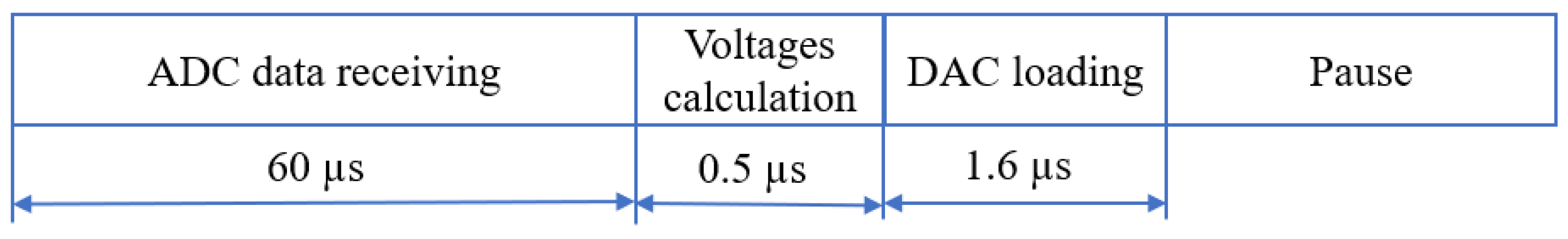
The cyclogram of the control module is presented in
Figure 9. The overall time for the implementation of the main operations took 62.1 µs; the most time-consuming operation (60 µs) was receiving data from the analog-to-digital converter. The limit frequency of such a system was 15 kHz; however, when changing the analog-to-digital converter operating mode to 16-bit, 30 kHz frequency could be reached. “Pause” on the cyclogram related to the tip-tilt mirror properties and was not taken into account; only control module characteristics were estimated. Based on the amplitude–resonance characteristics of the mirror, the “pause” should be about 2 ms to avoid mirror oscillations, which led to the frequency of the overall system to be 500 Hz.
3.4. Correction Algorithm
To stabilize the laser beam in a certain place and direction, the control module should continuously determine the deviation of the laser beam from it and drive the tip-tilt mirrors’ actuators. For example, a paraboloid interpolation algorithm was used in [
6] to estimate an image jitter at high resolution. A Jacobian matrix feedback controller was proposed in [
10], which was adaptive to the changes of the beam path. A centroid algorithm generated inverse response to the tip-tilt aberration to control for the tip-tilt mirror at UC Mount John Observatory [
24].
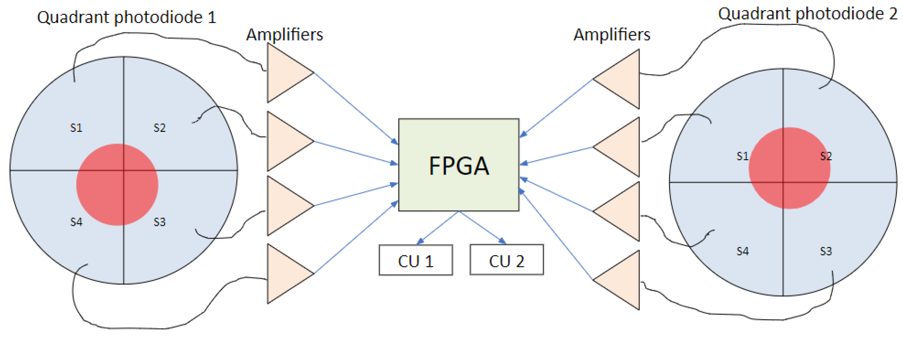
To calculate the control voltages, we used an algorithm based on the least square method [
25]. The information on the beam position was collected from the quadrant photodiodes (
Figure 10). We used FD-20KP quadrant photodiodes with a diameter of 10.2 mm and a gap of 0.3 mm between the four sectors. A standard 4-channel current-to-voltage conversion circuit on an operational amplifier [
26] with a conversion factor of 1,000,000 was produced to transmit the signals from each quadrant photodiode. The beam diameter on the photodiodes was 5 mm.
First, the equations set was composed as follows:
where U1–U4 are voltages to be applied to the drivers of the mirrors, and coefficients a11–a44 are normalizing values proportional to the response of the actuators, and X1/X2 and Y1/Y2 are the positions of the beam center on the photodiodes calculated as
S1–S4 are levels of the signal on the segments of the quadrant photodiodes.
The response functions of the actuators were measured when a unit voltage, for example, U1 = 10 V, was applied to one actuator of the mirror. When U1 was applied to the actuator #1 (X-actuator of the first tip-tilt mirror), the displacements of the focal spots on the photodiodes ΔX1(U1), ΔX2(U1), ΔY1(U1), and ΔY2(U1) were measured, and coefficients a11–a14 could be calculated as
where ΔX1/ΔX2 and ΔY1/ΔY2 are the displacements of the focal spot on the photodiodes. The same procedure was repeated for each of the four actuators, and, as a result, matrix A was filled as
With response functions measurements, the PC sent commands to the FPGA to set the voltages and to read the coordinates of the beam center. Then an inverse matrix |B| = |A|−1 was calculated by the PC, and the PC sent this matrix to the FPGA. The system was then calibrated.
The correction cycle includes three steps performed by the FPGA only:
The FPGA reads the signals from the photodiodes and determines the coordinates of the beam center on two photodiodes of X1, X2, Y1 or Y2, using Equations (5) and (6).
The voltages are calculated as
- 3.
The voltages are applied to the actuators of the tip-tilt correctors.
4. Results and Discussion
A photo of the setup to test the abilities of the stabilizing system is presented in
Figure 11. The laser beam is reflected from the tip-tilt mirrors and then detected with the quadrant photodiodes. The signal from the photodiodes is transferred to the FPGA. The FPGA analyzes the data and calculates and sends voltages to the drivers of the tip-tilt mirrors. The displacement of the beam position is saved for further analysis.
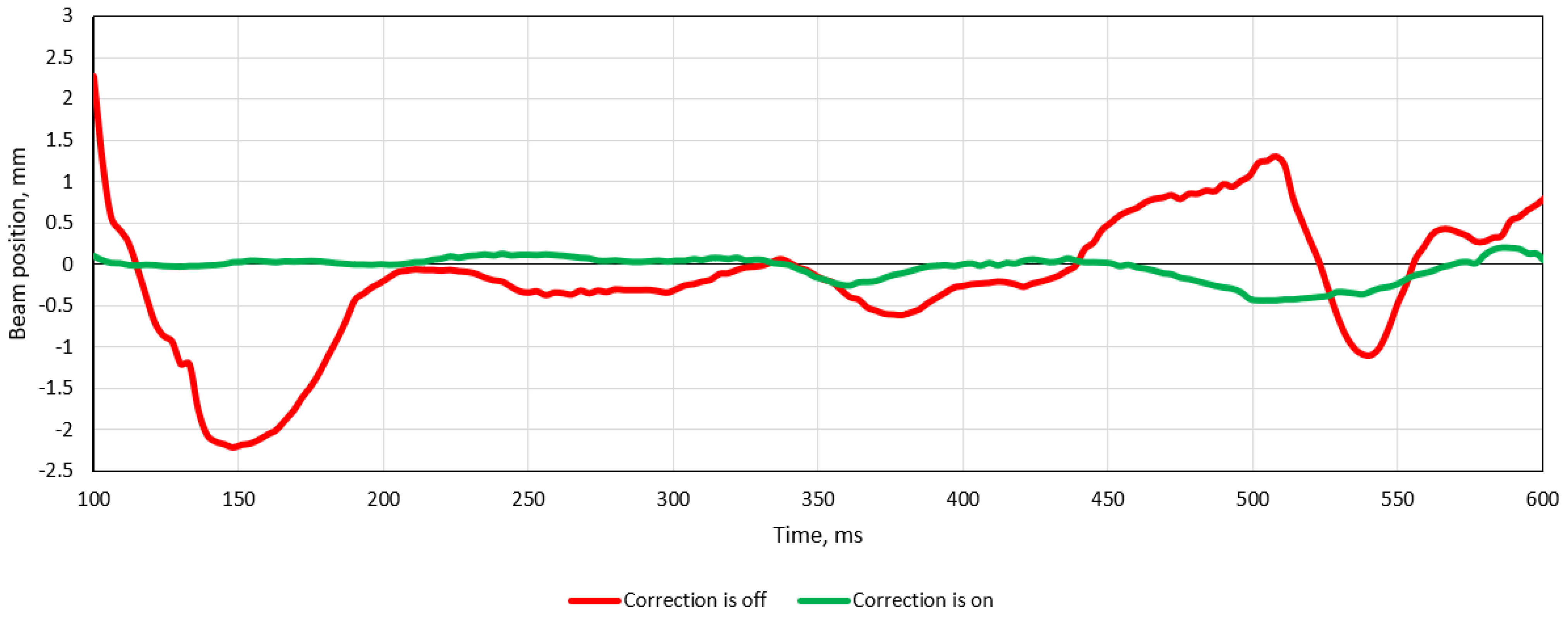
Figure 12 shows the measured fluctuation of the displacements on the first photodiode for 500 ms; the red line corresponds to the beam center position without any correction, and the green line shows the behavior of the beam center when correction is on.
The accuracy of the center position calculation on each photodiode was 0.25 μm. As the distance between the two photodiodes was 25 cm, the accuracy of the beam positioning was ±2 μrad.
The RMS of the beam position was calculated during 30 s both with and without correction. The RMS without correction was 1 mm, and it was 0.3 mm with the correction loop closed. The ratio between these data was 20 lg(RMSoff/RMSon), which showed that the system allowed the reduction of the amplitude of the beam position change up to 10 dB.
Regarding the electronics and mechanical elements, it is possible to achieve a required jitter reduction better than 10 dB. To improve the result, the beam diameter on the photodiodes should be optimized to provide a linear response at the positions close to the photodiode center; additionally, the type of photodiodes should be chosen, taking into account their signal-to-noise characteristics. One of the weak points might be an algorithm of correction based on proportional terms only. As a next step, it is necessary to modify the algorithm and integral and derivative terms.
For sure our laboratory setup was not equal to the real conditions at the telescope—herein, we wanted to present our results on a comparatively low-cost, reliable, and simple beam-stabilization system that could be installed on a 6 m telescope.
5. Conclusions
The FPGA platform was used to implement a beam-position-stabilization system. The system consists of two tip-tilt piezo-driven mirrors with control units and two quadrant photodiodes. The signals from the photodiodes are collected with the FPGA, and the control voltages necessary for the correction of the beam center displacement are calculated and applied to the actuators of the mirrors. The FPGA allows the speeding up of data processing and DAC/ADC data conversion, and the system performance only depends on the properties of the tip-tilt corrector and could be improved if necessary. The proposed beam-stabilization system allows reducing the beam jitter up to 10 dB. This number is actually not the expected one (for the BTA telescope, we need at least 5 times the jitter reduction), but we have the ideas and a way to improve it.
Author Contributions
Conceptualization, V.K. and J.S.; methodology, A.R.; software, V.B.; validation, I.G., A.N. and A.R.; formal analysis, A.R.; investigation, A.N.; resources, A.R.; data curation, A.K.; writing—original draft preparation, I.G.; writing—review and editing, A.K.; visualization, I.G.; supervision, V.K.; project administration, J.S.; funding acquisition, J.S. and A.K. All authors have read and agreed to the published version of the manuscript.
Funding
The investigations of the local correction or the beam position (Sections 3 and 4) were supported by the Russian Science Foundation under grant #20-19-00597, and the artificial turbulence investigation (Section 2) was supported by the state assignment of the Ministry of Science and Higher Education of the Russian Federation (theme No. 1021052706254-7-1.5.4).
Institutional Review Board Statement
Not applicable.
Informed Consent Statement
Not applicable.
Data Availability Statement
Not applicable.
Conflicts of Interest
The authors declare no conflict of interest.
References
- Ivanov, A.A.; Panchuk, V.E.; Shergin, V.S. SAO Preprint No. 155; Spec. Astrophys. Observ: Nizhny Arkhyz, Russia, 2001; pp. 1–19. [Google Scholar]
- Panchuk, V.; Klochkova, V.; Yushkin, M. The high-resolution echelle spectrograph of the 6-m telescope of the special astrophysical observatory. Astron. Rep. 2017, 61, 820–831. [Google Scholar] [CrossRef]
- Dong, Z.; Jiang, A.; Dai, Y.; Xue, J. Space-qualified fast steering mirror for an image stabilization system of space astronomical telescopes. Appl. Opt. 2018, 57, 9307. [Google Scholar] [CrossRef] [PubMed]
- Shimizu, T.; Nagata, S.; Tsuneta, S.; Tarbell, T.; Edwards, C.; Shine, R.; Hoffmann, C.; Thomas, E.; Sour, S.; Rehse, R.; et al. Image stabilization system for Hinode (Solar-B) solar optical telescope. Sol. Phys. 2008, 249, 221–232. [Google Scholar] [CrossRef]
- Casas, A.; Gómez Cama, J.M.; Roma, D.; Carmona, M.; Bosch, J.; Herms, A.; Sabater, J.; Volkmer, R.; Heidecke, F.; Maue, T.; et al. Design and test of a tip-tilt controller for an image stabilization system. Proc. SPIE 2016, 9911, 991123. [Google Scholar] [CrossRef]
- Roma, D.; Carmona, M.; Bosch, J.; Casas, A.; Herms, A.; Lopez, M.; Ruiz, O.; Sabater, J.; Berkefeld, T.; Maue, T.; et al. Subpixel real-time jitter detection algorithm and implementation forpolarimetric and helioseismic imager. J. Astron. Telesc. Instrum. Syst. 2019, 5, 039003. [Google Scholar] [CrossRef]
- Chenghao, L.; Xu, H.; Qi, J.; Xiaohui, Z.; Kuo, F. Theoretical and experimental study on the testing accuracy of the image stabilization system of a space astronomical telescope. Appl. Opt. 2020, 59, 6658–6670. [Google Scholar] [CrossRef]
- Canuto, E.; Musso, F. Active angular stabilization of the GAIA space telescope through laser interferometry. IFAC Proc. Vol. 2004, 37, 955–960. [Google Scholar] [CrossRef]
- Tyszka, K.; Dobosz, M. Laser beam angular stabilization system based on a compact interferometer and a precise double-wedge deflector. Rev. Sci. Instrum. 2018, 89, 085121. [Google Scholar] [CrossRef]
- Chang, H.; Ge, W.-Q.; Wang, H.-C.; Yuan, H.; Fan, Z.-W. Laser beam pointing stabilization control through disturbance classification. Sensors 2021, 21, 1946. [Google Scholar] [CrossRef]
- Sheldakova, J.; Galaktionov, I.; Nikitin, A.; Alexandrov, A.; Kudryashov, A.; Belousov, V.; Rukosuev, A. FPGA based laser beam stabilization system. Proc. SPIE 2022, 11987, 119870C. [Google Scholar] [CrossRef]
- Klochkova, V.G.; Sheldakova, Y.V.; Vlasyuk, V.V.; Kudryashov, A.V. Improving the efficiency of high-resolution spectroscopy on the 6-m telescope using adaptive optics techniques. Astrophys. Bull. 2020, 75, 468–481. [Google Scholar] [CrossRef]
- Rukosuev, A.; Nikitin, A.; Belousov, V.; Sheldakova, J.; Toporovsky, V.; Kudryashov, A. Expansion of the laser beam wavefront in terms of zernike polynomials in the problem of turbulence testing. Appl. Sci. 2021, 11, 12112. [Google Scholar] [CrossRef]
- Neal, D.R.; Pulaski, P.; Raymond, T.D.; Neal, D.A. Testing highly aberrated large optics with a Shack-Hartmann wavefront sensor. Proc. SPIE 2003, 5162, 129–138. [Google Scholar] [CrossRef]
- Mansuripur, M. The Shack-Hartmann Wavefront sensor. Opt. Photonics News 1999, 10, 48–51. [Google Scholar] [CrossRef]
- Wilson, R.W. SLODAR: Measuring optical turbulence altitude with a Shack–Hartmann wavefront sensor. Mon. Not. R. Astron. Soc. 2002, 337, 103–108. [Google Scholar] [CrossRef] [Green Version]
- Primot, J. Theoretical description of Shack–Hartmann wave-front sensor. Opt. Commun. 2003, 222, 81–92. [Google Scholar] [CrossRef]
- Nikitin, A.; Sheldakova, J.; Kudryashov, A.; Borsoni, G.; Denisov, D.; Karasik, V.; Sakharov, A. A device based on the Shack-Hartmann wave front sensor for testing wide aperture optics. Proc. SPIE 2016, 9754, 97540K. [Google Scholar] [CrossRef]
- Kudryashov, A.; Rukosuev, A.; Nikitin, A.; Galaktionov, I.; Sheldakova, J. Real-time 1.5 kHz adaptive optical system to correct for atmospheric turbulence. Opt. Express 2020, 28, 37546–37552. [Google Scholar] [CrossRef]
- Southwell, W.H. Wave-front estimation from wave-front slope measurements. J. Opt. Soc. Am. 1980, 70, 998–1006. [Google Scholar] [CrossRef]
- Neal, D.R.; Copland, J.; Neal, D.A. Shack-Hartmann wavefront sensor precision and accuracy. Proc. SPIE 2002, 4779, 148–160. [Google Scholar] [CrossRef]
- Hippler, S. Adaptive optics for extremely large telescopes. J. Astron. Instrum. 2019, 8, 1950001. [Google Scholar] [CrossRef] [Green Version]
- Noll, R.J. Zernike polynomials and atmospheric turbulence. J. Opt. Soc. Am. 1976, 66, 207–211. [Google Scholar] [CrossRef]
- Liu, J.; Muruganandan, V.; Clare, R.; Ramirez Trujillo, M.C.; Weddell, S. A tip-tilt mirror control system for partial image correction at UC mount john observatory. In Proceedings of the 35th International Conference on Image and Vision Computing New Zealand (IVCNZ), Wellington, New Zealand, 25–27 November 2020; pp. 1–6. [Google Scholar] [CrossRef]
- Kudryashov, A.; Alexandrov, A.; Rukosuev, A.; Samarkin, V.; Galarneau, P.; Turbide, S.; Châteauneuf, F. Extremely high-power CO2 laser beam correction. Appl. Opt. 2015, 54, 4352–4358. [Google Scholar] [CrossRef] [PubMed]
- Horowitz, P.; Hill, W. The Art of Electronics, 3rd ed.; Cambridge University Press: New York, NY, USA, 2015. [Google Scholar]
| Publisher’s Note: MDPI stays neutral with regard to jurisdictional claims in published maps and institutional affiliations. |
© 2022 by the authors. Licensee MDPI, Basel, Switzerland. This article is an open access article distributed under the terms and conditions of the Creative Commons Attribution (CC BY) license (https://creativecommons.org/licenses/by/4.0/).

 ,
, 

