Communication

Theoretical Investigation of Bandwidth in Multimode Step-Index Silica Photonic Crystal Fibers

1
Faculty of Sciences and Mathematics, University of Priština in Kosovska Mitrovica, L. Ribara 29, 38220 Kosovska Mitrovica, Serbia
2
Faculty of Science, University of Kragujevac, R. Domanovića 12, 34000 Kragujevac, Serbia
3
Department of Mechanical Engineering, City University of Hong Kong, Hong Kong, China
4
Center for Cognition and Neuroergonomics, State Key Laboratory of Cognitive Neuroscience and Learning, Beijing Normal University at Zhuhai, Zhuhai 519087, China
*
Author to whom correspondence should be addressed.
Photonics 2022, 9(4), 214; https://doi.org/10.3390/photonics9040214
Submission received: 28 February 2022 / Revised: 19 March 2022 / Accepted: 22 March 2022 / Published: 23 March 2022
(This article belongs to the Special Issue Application of Multimode Optical Fibers)

Abstract

:
Solving the time-dependent power flow equation (PFE) provides a useful method to study the transmission bandwidth of step-index silica photonic crystal fibers (SI SPCFs). The transmission bandwidth of these kinds of fibers is determined for different air-hole structures (different numerical apertures (NAs)) and different distribution widths of the Gaussian launch beam. The results indicate that the lower the NA of SI SPCFs, the higher the bandwidth (for example, for a lower NA of SI SPCFs, a bandwidth that is eight times larger is obtained at a fiber length of 3500 m). The narrower launch beam at short fiber lengths results in a wider bandwidth. The longer the fiber (>300 m), the much less the effect of the launch beam width on the bandwidth. The bandwidth becomes independent of the width of the launch beam distribution at the fiber length at which a steady-state distribution (SSD) is reached. These results are useful for some potential applications, such as high capacity transmission optical fiber systems.

1. Introduction

The communication system based on optical fibers provides more reliability and flexibility than the wireless communication medium, which is the backbone of the modern telecommunication network [1]. The PCF first investigated by the Russell group is a specific optical fiber technology (optical fiber with micro-structure) for light guiding [2]. The light passing through PCFs follows two principles: the first one is light passing through a high refractive index (RI) medium surrounded by a lower RI medium, and the other one is light passing through a low RI medium surrounded by a higher RI medium. For some kinds of PCFs, a high RI material, such as silica material, is implemented as the background material, which is doped in a periodic manner with air holes. The hole pattern has lowered the effective RI of the fiber cladding and allows the optical fibers to guide light [2,3,4,5,6,7]. Choosing this cladding hole pattern allows one to adjust the RI profile of the optical fiber during the design process. PCFs exhibit excellent performance as the microstructure of the fibers provides additional flexibility to influence the cross-section during the design phase. The “end-less” PCF [2] has been shown to work only in fundamental mode over a wide range of wavelengths. On the other hand, a PCF may have an empty core. Photonic gap guidance [8,9,10,11] allows the “air center” of hollow fibers to have a lower RI than the RI of the cladding material [12,13]. In practice, optical dispersion and birefringence of PCFs is often investigated [14,15,16,17]. Nowadays, PCFs are important since they can be implemented for many applications, such as supercontinuum light generation [18,19,20], light wavelength conversion [21,22], optical fluids [23], and different sensing area [24]. The width of the PCF material between the holes of the cladding determines the NA of the PCF, which is normally limited to NA ≃ 0.5–0.6 [25,26,27]. Sometimes, PCFs considered include heavy metal oxide glass fibers [28] and liquid-filled hollow-core fibers for specific applications [29]. Additionally, high NA PCFs demonstrated excellent resolution in lensless focusing [30].
PCFs show high bandwidth performance and flexibility, making them useful for transmission and sensing technology. The propagation characteristics of PCFs are important parameters for their practical applications, which are affected by mode attenuation, mode coupling, and modal dispersion. The main cause of mode coupling lies in light scattering due to intrinsic perturbations in the fiber (micro-bend, changes in diameter, and changes in density and RI distribution). One of the most efficient approaches in modeling the transmission characteristics of multimode optical fibers is based on the employment of the PFE [31,32,33,34,35,36]. In this work, by solving the time-dependent PFE, we determine the bandwidth of a multimode SI SPCF with a solid core for two different launch beam distribution widths and two different air-hole sizes (two different NAs), which have a great potential for applications in optical fiber communication. The central part has the highest RI; holes with diameter d and pitch Λ in the cladding reduce the effective value of RI in the cladding.

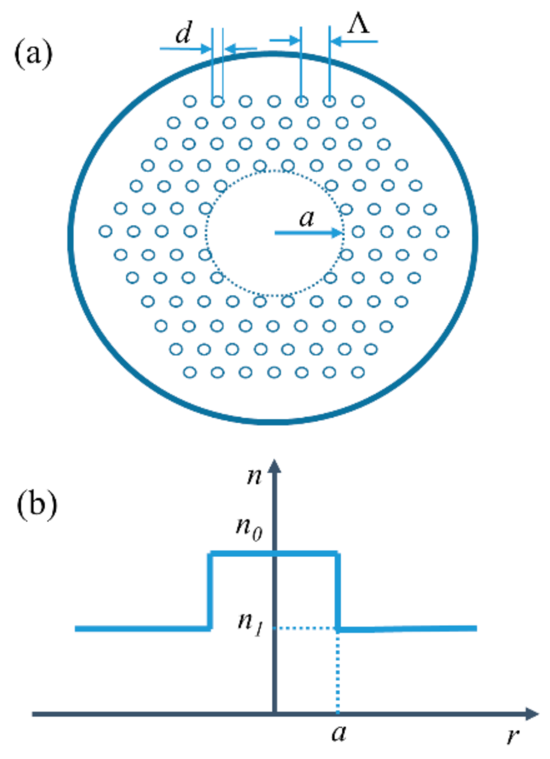
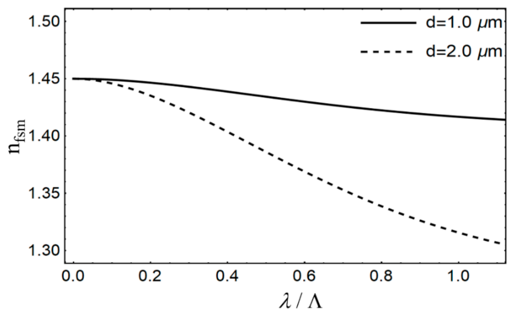
2. The Design of the PCF

Here, we present a SI PCF design in which the air holes are uniform in size and form an equilateral triangular network in the cladding, as shown in Figure 1. Despite the fact that the material properties are uniform throughout the optical fiber, the hole-free central part has the highest RI; holes with diameter d and pitch Λ in the cladding reduce the effective value of RI in the cladding.

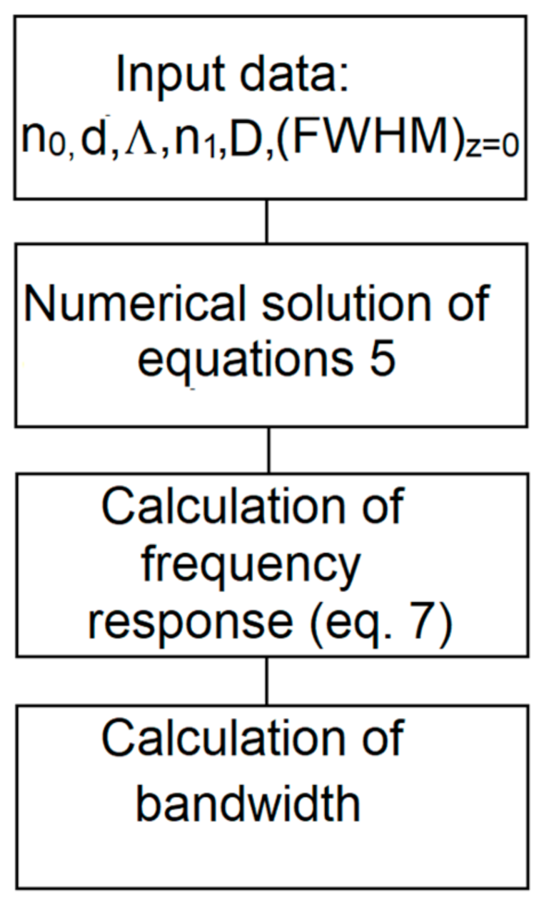
3. The Time-Dependent PFE

We used the time-dependent PFE for the bandwidth simulation, which is presented in the following form [31]:
p ( θ , z , t ) z + τ ( θ ) p ( θ , z , t ) t = α ( θ ) P ( θ , z , t ) + 1 θ θ [ D ( θ ) p ( θ , z , t ) θ ]
where t is the time, θ is the angle, z is the optical fiber length, p ( θ , z , t ) is the power distribution, τ ( θ ) is the modal delay, D ( θ ) is the coupling coefficient (usually assumed constant [31,32]), and α(θ) ≃ α0 (it does not have to be accounted when solving (1)) [32].
The Fourier transformation of Equation (1) is:
P ( θ , z , ω ) z + j ω τ ( θ ) P ( θ , z , ω ) = α ( θ ) P ( θ , z , ω ) + 1 θ θ [ θ D ( θ ) P ( θ , z , ω ) θ ]
where ω = 2 π f is the angular frequency, and we obtain:
P ( θ , z , ω ) = + p ( θ , z , t ) exp ( j ω t ) d t
The boundary conditions are presented in the following form:
P ( θ m , z , ω ) = 0 , D ( θ ) P ( θ , z , ω ) θ θ = 0 = 0
Since P θ , z , ω has the real part P r θ , z , ω and imaginary part P i θ , z , ω , Equation (2) can be rewritten as:
P r ( θ , z , ω ) z = α ( θ ) P r ( θ , z , ω ) + D θ P r ( θ , z , ω ) θ + D 2 P r ( θ , z , ω ) θ 2 + ω τ P i ( θ , z , ω ) P i ( θ , z , ω ) z = α ( θ ) P i ( θ , z , ω ) + D θ P i ( θ , z , ω ) θ + D 2 P i ( θ , z , ω ) θ 2 ω τ P r ( θ , z , ω )
where
P ( θ , z , ω ) = P r ( θ , z , ω ) + j P i ( θ , z , ω )
We obtained P r ( θ , z , ω ) and P i ( θ , z , ω ) by numerically solving Equation (5) using the explicit finite difference method (EFDM). The frequency response H ( z , ω ) is then obtained as:
H ( z , ω ) = 2 π 0 θ m θ [ P r ( θ , z , ω ) + j P i ( θ , z , ω ) ] d θ 2 π 0 θ m θ [ P r ( θ , 0 , ω ) + j P i ( θ , 0 , ω ) ] d θ
This equation can be used to determine the change of the transmission bandwidth with the transmission length.

4. Simulation Results

The bandwidth for various launch beam distribution widths in the multimode SI SPCF was investigated. For a PCF with triangular lattice air holes, the effective parameter V is presented as:
V = 2 π λ a e f f n 0 2 n f s m 2
where n0 is the RI of the core, nfsm is the effective RI of the cladding, and a e f f = Λ / 3 [33]. The effective RI of the cladding n1nfsm, can be obtained from Equation (8), using the following equation [33]:
V λ Λ , d Λ   =   A 1 + A 2 1 + A 3 exp A 4 λ / Λ
where the parameters for fitting A i (i = 1 to 4) are presented as:
A i = a i 0 + a i 1 d Λ b i 1 + a i 2 d Λ b i 2 + a i 3 d Λ b i 3
where the coefficients a i 0 to a i 3 and b i 1 to b i 3 (i = 1 to 4) are supplied in Table 1.
Figure 2 shows the cladding’s effective RI n1 ≡ nfsm as a function of λ / Λ , for Λ = 3 μ m and for two values of the hole diameter d. The design parameters of the investigated SI SPCF are presented in Table 2.
The Equation (5) are solved using the EFDM [34], where the coupling coefficient was D = 2.3 × 10 6 rad 2 / m (typical value of D for glass core fibers [35]). The cases with diameter of air holes d = 1 µm (n1 = 1.443717, Δ = 0.00433) and d = 2 µm (n1 = 1.423679, Δ = 0.01815) and launch beam distribution with (FWHM)z=0 = 1° and 5° are analyzed.
For illustration purposes, Figure 3 shows the bandwidth expansion over the fiber length. This was calculated for the beam distributions with (FWHM)z=0 = 1° and 5°, in the case of Δ = 0.00433 and Δ = 0.01815. From Figure 3, we can observe that a lower NA (smaller Δ) yields a higher bandwidth. For shorter fiber lengths, the smaller the Gaussian launch beam width, the wider the bandwidth. This is due to the narrow launch beam of (FWHM)z=0 = 1°, which reduces the modal dispersion. The effect of the (FWHM)z=0 of the launch beam distribution on the bandwidth vanishes with increasing the optical fiber length. Initial mode excitation has less effect on the bandwidth of longer fibers, because mode coupling affects the redistribution of energy between guide modes. Figure 3 shows a linear decrease in the bandwidth over short fiber lengths before switching to a 1/z1/2 functional dependence. For the larger widths of the Gaussian launch beams and lower NAs, this change, and therefore the equilibrium mode distribution, occurs at shorter fiber lengths. For (FWHM)z=0 = 1°, the length is Lc ≃ 500 m for n1 = 1.443717 and Lc ≃ 1650 m for n1 = 1.423679. For (FWHM)z=0 = 5°, the length is Lc ≃ 300 m for n1 = 1.443717 and Lc ≃ 1450 m for n1 = 1.423679 [36]. The shorter the length Lc, the slower the bandwidth decrease. The bandwidth tends to be length-independent for certain fiber lengths. This length marks the onset of an SSD. This length is z S S D 1150 m for n1 = 1.443717 and z SSD 3800 m for n1 = 1.423679 [36]. Finally, one can conclude that the examined PCFs seem to be suitable for short-haul rather than long-haul applications.
It is worth noting that the proposed method for the investigation of the bandwidth in SI SPCFs by employing the time-dependent power flow equation has already been proven as effective and accurate in several previously published works, including the theoretical and experimental investigation of bandwidths in graded-index plastic optical fibers and SI plastic optical fibers [34,37]. A block diagram that illustrates the procedure applied in this work for the calculation of the bandwidth in SI SPCFs is shown in Figure 4.

5. Conclusions

To conclude, by solving the time-dependent PFE, an approach for estimating the bandwidth of multimode SI SPCFs is proposed. From the obtained results, we conclude that lower NA enables a higher fiber bandwidth (e.g., for lower NA of SI SPCFs, a bandwidth that is eight times larger is obtained at a fiber length of 3500 m). Additionally, a narrower Gaussian launch beam leads to a higher bandwidth at short fiber lengths. The bandwidth decreases with increasing the fiber length and tends to be launch-beam independent for a certain fiber length. This length marks the onset of the SSD. One can conclude that the examined PCFs seem to be suitable for short-haul rather than long-haul applications. Finally, we show that these tuning parameters provide additional flexibility in the construction of photonic crystal fibers for high bandwidth optical fiber transmission.

Author Contributions

Methodology, software, B.D. and M.S.K.; writing—original draft preparation, S.S., L.K. and A.S.; writing—review and editing, A.D., S.S. and R.M.; funding acquisition, S.S. and R.M. All authors have read and agreed to the published version of the manuscript.

Funding

This research was funded by the NSFC (62003046, 6211101138); City University of Hong Kong (CityU 7004600); Serbian Ministry of Education, Science and Technological Development (451-03-68/2022-14/200122); Science Fund of the Republic of Serbia (CTPCF-6379382); Guangdong Provincial Department of Technology (2021A1515011997); Guangdong Provincial Department of Education (2021ZDZX1050,2021KCXTD014); and Guangdong Provincial Department of Science and Technology(2021A1313030055).

Institutional Review Board Statement

Not applicable.

Informed Consent Statement

Not applicable.

Data Availability Statement

The data presented in this study are available on request from the corresponding author.

Conflicts of Interest

The authors declare no conflict of interest.

References

  1. Knight, J.C.; Birks, T.A.; Russell, P.S.J.; Atkin, D.M. All-silica single-mode optical fiber with photonic crystal cladding. Opt. Lett. 1996, 21, 1547–1549. [Google Scholar] [CrossRef] [PubMed]
  2. Birks, T.A.; Knight, J.C.; Russell, P.S.J. Endlessly single-mode photonic crystal fiber. Opt. Lett. 1997, 22, 961–963. [Google Scholar] [CrossRef] [PubMed]
  3. Russell, P.S.J. Photonic crystal fibers. Science 2003, 299, 358–362. [Google Scholar] [CrossRef] [PubMed]
  4. Knight, J.C. Photonic crystal fiber. Nature 2003, 424, 847–851. [Google Scholar] [CrossRef]
  5. Russell, P.S.J. Photonic-crystal fibers. J. Lightwave Technol. 2006, 24, 4729–4749. [Google Scholar] [CrossRef]
  6. Knight, J.C.; Broeng, J.; Birks, T.A.; Russell, P.S.J. Photonic Band Gap Guidance in Optical Fibers. Science 1998, 282, 1476–1478. [Google Scholar] [CrossRef]
  7. Knight, J.C.; Russell, P.S.J. Photonic crystal fibers: New way to guide light. Science 2002, 296, 276–277. [Google Scholar] [CrossRef]
  8. Cregan, R.F.; Mangan, B.J.; Knight, J.C.; Birks, T.A.; Russell, P.S.J.; Roberts, P.J.; Allan, D.C. Single-Mode Photonic Band Gap Guidance of Light in Air. Science 1999, 285, 1537–1539. [Google Scholar] [CrossRef] [Green Version]
  9. Amezcua-Correa, R.; Gèrôme, F.; Leon-Saval, S.; Broderick, N.G.R.; Birks, T.; Knight, J. Control of surface modes in low loss hollow-core photonic bandgap fibers. Opt. Express 2008, 16, 1142–1149. [Google Scholar] [CrossRef] [Green Version]
  10. Zhang, Z.; He, J.; Du, B.; Guo, K.; Wang, Y. Highly sensitive gas refractive index sensor based on hollow-core photonic bandgap fiber. Opt. Express 2009, 27, 29649–29658. [Google Scholar] [CrossRef]
  11. Zhang, X.; Gao, S.; Wang, Y.; Ding, W.; Wang, X.; Wang, P. 7-cell hollow-core photonic bandgap fiber with broad spectral bandwidth and low loss. Opt. Express 2019, 27, 11608–11616. [Google Scholar] [CrossRef]
  12. Benabid, F.; Knight, J.C.; Antonopoulos, G.; Russell, P.S.J. Stimulated Raman Scattering in Hydrogen-Filled Hollow-Core Photonic Crystal Fiber. Science 2002, 298, 399–402. [Google Scholar] [CrossRef]
  13. Light, P.; Benabid, F.; Couny, F.; Maric, M.; Luiten, A. Electromagnetically induced transparency in Rb-filled coated hollow-core photonic crystal fiber. Opt. Lett. 2007, 32, 1323–1325. [Google Scholar] [CrossRef]
  14. Mogilevtsev, D.; Birks, T.; Russell, P. Group-velocity dispersion in photonic crystal fibers. Opt. Lett. 1998, 23, 1662–1664. [Google Scholar] [CrossRef]
  15. Nair, A.A.; Amiri, I.S.; Boopathi, C.S.; Karthikumar, S.; Jayaraju, M.; Yupapin, P. Numerical investigation of co-doped microstructured fiber with two zero-dispersion wavelengths. Results Phys. 2018, 10, 766–771. [Google Scholar] [CrossRef]
  16. Huang, Y.; Yang, H.; Zhao, S.; Mao, Y.; Chen, S. Design of photonic crystal fibers with flat dispersion and three zero dispersion wavelengths for coherent supercontinuum generation in both normal and anomalous regions. Results Phys. 2021, 23, 104033. [Google Scholar] [CrossRef]
  17. Anas, T.; Asaduzzaman, S.; Ahmed, K.; Bhuiyan, T. Investigation of highly birefringent and highly nonlinear Hexa Sectored PCF with low confinement loss. Results Phys. 2018, 11, 1039–1043. [Google Scholar] [CrossRef]
  18. Rajesh, A.; Chandru, S.; Robinson, S. Investigation of defective hybrid cladding with silicon nanocrystal PCF for super-continuum generation. Laser Phys. 2021, 31, 126206. [Google Scholar] [CrossRef]
  19. Kuliesaite, M.; Jarutis, V.; Pimpe, J.; Vengelis, J. Partially coherent UV–VIS light generation in photonic crystal fiber using femtosecond pulses. Results Phys. 2021, 31, 104965. [Google Scholar] [CrossRef]
  20. Paul, B.K.; Moctader, M.G.; Ahmed, K.; Khalek, M.A. Nanoscale GaP strips based photonic crystal fiber with high non-linearity and high numerical aperture for laser applications. Results Phys. 2018, 10, 374–378. [Google Scholar] [CrossRef]
  21. Wu, D.; Guo, Z.; Wu, Z.; Shum, P. 900 nm waveband four wave mixing generation in highly nonlinear photonic crystal fiber. J. Opt. 2018, 20, 035501. [Google Scholar] [CrossRef]
  22. Yuan, J.; Kang, Z.; Li, F.; Zhou, G.; Sang, X.; Wu, Q.; Yan, B.; Zhou, X.; Zhong, K.; Wang, L.; et al. Polarization-dependent intermodal four-wave mixing in a birefringent multimode photonic crystal fiber. Opt. Lett. 2017, 42, 1644–1647. [Google Scholar] [CrossRef] [Green Version]
  23. Das, S.; De, M.; Singh, V.K. Single mode dispersion shifted photonic crystal fiber with liquid core for optofluidic applications. Opt. Fiber Technol. 2019, 53, 102012. [Google Scholar] [CrossRef]
  24. Monfared, Y.E.; Liang, C.; Khosravi, R.; Kacerovska, B.; Yang, S. Selectively toluene-filled photonic crystal fiber Sagnac interferometer with high sensitivity for temperature sensing applications. Results Phys. 2019, 13, 102297. [Google Scholar] [CrossRef]
  25. Wadsworth, W.; Percival, R.; Bouwmans, G.; Knight, J.; Birks, T.; Hedley, T.; Russell, P. Very High Numerical Aperture Fibers. IEEE Photon. Technol. Lett. 2004, 16, 843–845. [Google Scholar] [CrossRef] [Green Version]
  26. Hansen, K.P.; Broeng, J.; Petersson, A.; Nielsen, M.D.; Skovgaard, P.M.W.; Jakobsen, C.; Simonsen, H.R. High-power photonic crystal fibers. Proc. SPIE 2006, 6102, 61020B. [Google Scholar] [CrossRef]
  27. Olausson, C.B.; Hansen, K.P.; Broeng, J.; Noordegraaf, D.; Maack, M.D.; Alkeskjold, T.T.; Laurila, M.; Nikolajsen, T.; Skovgaard, P.M.W.; Sørensen, M.H.; et al. Airclad fiber laser technology. Opt. Eng. 2011, 50, 111609. [Google Scholar] [CrossRef] [Green Version]
  28. Stepien, R.; Siwicki, B.; Pysz, D.; Stepniewski, G.; Kujawa, I.; Klimczak, M.; Buczynski, R. Characterization of a large core photonic crystal fiber made of lead–bismuth–gallium oxide glass for broadband infrared transmission. Opt. Quantum Electron. 2014, 46, 553–561. [Google Scholar] [CrossRef] [Green Version]
  29. Tefelska, M.M.; Ertman, S.; Wolinski, T.R.; Mergo, P.; Dabrowski, R. Large Area Multimode Photonic Band-Gap Propagation in Photonic Liquid-Crystal Fiber. IEEE Photon. Technol. Lett. 2012, 24, 631–633. [Google Scholar] [CrossRef]
  30. Amitonova, L.V.; Descloux, A.; Petschulat, J.; Frosz, M.H.; Ahmed, G.; Babic, F.; Jiang, X.; Mosk, A.P.; Russell, P.; Pinkse, P.W.H. High-resolution wavefront shaping with a photonic crystal fiber for multimode fiber imaging. Opt. Lett. 2016, 41, 497–500. [Google Scholar] [CrossRef]
  31. Gloge, D. Optical Power Flow in Multimode Fibers. Bell Syst. Tech. J. 1972, 51, 1767–1783. [Google Scholar] [CrossRef]
  32. Rousseau, M.; Jeunhomme, L. Numerical Solution of the Coupled-Power Equation in Step-Index Optical Fibers. IEEE Trans. Microw. Theory Tech. 1977, 25, 577–585. [Google Scholar] [CrossRef]
  33. Saitoh, K.; Koshiba, M. Empirical relations for simple design of photonic crystal fibers. Opt. Express 2005, 13, 267–274. [Google Scholar] [CrossRef] [PubMed]
  34. Simović, A.; Drljača, B.; Savović, S.; Djordjevich, A.; Min, R. Investigation of bandwidth in multimode graded-index plastic optical fibers. Opt. Express 2021, 29, 29587–29594. [Google Scholar] [CrossRef]
  35. Tanaka, T.P.; Yamada, S. Steady-state characteristics of multimode W-type fibers. Appl. Opt. 1979, 18, 3261–3264. [Google Scholar] [CrossRef]
  36. Savović, S.; Kovačević, M.S.; Simović, A.; Kuzmanović, L.; Drljača, B.; Djordjevich, A. Method for investigation of mode coupling in multimode step-index silica photonic crystal fibers. Optik 2021, 246, 167728. [Google Scholar] [CrossRef]
  37. Savović, S.; Drljača, B.; Kovačević, M.S.; Djordjevich, A.; Bajić, J.S.; Stupar, D.Z.; Stepniak, G. Frequency response and bandwidth in low NA step index plastic optical fibers. Appl. Opt. 2014, 53, 6999–7003. [Google Scholar] [CrossRef]
Figure 1. (a) Lateral end-face of a solid-core multimode SI PCF, where Λ is the pitch and d is the diameter of the air holes. (b) RI profile of a multimode SI PCF.
Photonics 09 00214 g001
Figure 2. Effective RI of the inner cladding as a function of λ / Λ .
Photonics 09 00214 g002
Figure 3. Bandwidth as a function of the optical fiber length for the Gaussian launch beams with (FWHM)z=0 = 1° and 5° for Δ = 0.00433 Δ = 0.01815.
Photonics 09 00214 g003
Figure 4. Block diagram for the calculation of the bandwidth in SI SPCFs.
Photonics 09 00214 g004
Table 1. Fitting coefficients in Equation (10) [33].
i = 1 i = 2 i = 3 i = 4
a i 0 0.548080.710410.16904−1.52736
a i 1 5.004019.734911.857651.06745
a i 2 −10.4324847.4149618.968491.93229
a i 3 8.22992−43.750962−42.43183.89
b i 1 51.81.7−0.84
b i 2 77.32101.02
b i 3 922.81413.4
Table 2. Effective RI of the cladding n 1 , relative RI difference Δ   =   n 0 n 1 / n 0 , where n 0 = 1.45, and the critical angle θ m for the varied air-hole diameter d at wavelength 850 nm.
d (µm)1.02.0
n 1 1.4437171.423679
Δ   =   n 0 n 1 / n 0 0.004330.01815
θ m (deg)5.3410.93
Publisher’s Note: MDPI stays neutral with regard to jurisdictional claims in published maps and institutional affiliations.

