Communication

A Single-Pixel Imaging Scheme with Obstacle Detection

1
School of Information Science and Engineering, Shandong University, Qingdao 266237, China
2
Key Laboratory of Laser & Infrared System (Shandong University), Ministry of Education, Shandong University, Qingdao 266237, China
*
Author to whom correspondence should be addressed.
Photonics 2022, 9(4), 253; https://doi.org/10.3390/photonics9040253
Submission received: 18 February 2022 / Revised: 20 March 2022 / Accepted: 21 March 2022 / Published: 11 April 2022
(This article belongs to the Special Issue Smart Pixels and Imaging)

Abstract

:
Single-pixel imaging (SPI) utilizes a second-order correlation of structured illumination light field and a single-pixel detector to form images. As the single-pixel detector provides no spatial resolution, a structured illumination light field generated by devices such as a spatial light modulator substitutes the role of array camera to retrieve pixel-wise spatial information. Due to its unique imaging modality, SPI has certain advantages. Meanwhile, its counterintuitive configuration and reciprocity relation to traditional array cameras have been studied to understand its fundamental principle. According to previous studies, the non-spatial detection property makes it possible for SPI to resist scattering in the detection part. In this work, we study the influence of an obstacle aperture in the detection part of SPI. We notice that such an obstacle aperture can restrict the field-of-view (FOV) of SPI, which can be diminished by a scattering process. We investigate these properties with experiment results and analysis under geometry optics. We believe that our study will be helpful in understanding the counterintuitive configuration of SPI and its reciprocity to traditional imaging.

1. Introduction

Traditional imaging system utilizes detector arrays, such as the charge-coupled device (CCD) and complementary metal oxide semiconductor (CMOS), accomplish the imaging process with the direct detection of light intensity on the image plane. By contrast, a single-pixel imaging (SPI) system, or a single-pixel camera (SPC), images the target with a non-spatially resolving detector that only contains one pixel, i.e., single-pixel detector, which is also known as a bucket detector. Unlike traditional imaging, the spatial resolution of the image captured by SPC is not determined by the detector, but by a sequence of structured illumination light fields with specific light intensity distribution which are incident to the surface of the object. Because of its unique imaging mechanism, this new computational imaging technology has arose extensive research interest in the past two decades.
SPI utilises second-order correlation of light field to retrieve spatial information. Its development has been largely motivated by ghost imaging (GI). To start with, GI is first demonstrated using quantum entanglement [1]. Later on it is demonstrated that GI can also be performed with classical illumination [2,3] or even in a computational modality [4]. Computational ghost imaging scheme requires only single-pixel detectors and therefore named as SPI. Since developed, it has been widely applied in many fields, such as three-dimensional imaging [5,6,7], ultrafast imaging [8,9,10] etc. Due to the wide response waveband and high sensitivity of single-pixel detectors, SPI is very suitable for imaging in special wavebands such as infrared [11,12], ultraviolet [13,14], terahertz [15,16,17] and even X-ray [18,19,20] or multispectral imaging [21,22] and hyperspectral imaging [23,24].
With the development of SPI technology, its advantages have been highlighted and applied in many complex environments. For traditional cameras, its image quality is affected by atmospheric turbulence and other scattering media. However, SPI has advantages in this aspect and has an anti-interference capacity. Han, et al. demonstrated through simulations and experiments that the performance of SPI is superior to traditional imaging through atmospheric turbulence [25]. P. Ben Dixon, et al. proposed a theoretical model and demonstrated that the impact of atmospheric turbulence is greatly reduced in SPI [26]. Zhang et al. combined Fourier filter and conditional generative adversarial network (CGAN) to further reduce the imfact of atmospheric turbulence in Fourier SPI [27]. Y. Jauregui-Sánchez et al. showed that SPI has a better performance over traditional imaging though scattering media by the Fourier gating [28]. In the presence of scattering media, three-dimensional imaging [29], polarimetric imaging [30] and microscopic imaging [31] can still be realized under SPI mechanism.
In recent years, efforts have been made to explore the potential of SPI through scattering media. However, inspired by reciprocity between SPC and an array camera system, it occurs to us that the characteristics of scattering media can also be used. In a normal camera system, disturbance in the illumination part between light source and object could change the shading or light uniformity in the imaging process, but does not affect the imaging configuration. In a SPC, this principle is valid in the detection part, as a single-pixel detector with no spatial resolution is analogue to the light source in an array camera system. If we insert a sheet of ground glass between the object and the detector in SPC, it can still produce images given sufficient signal. In order to form an image, what can not be interrupted, just as the imaging process between the object and the array camera, is the projection process of structured illumination light field between the projector and the object. Therefore, if some obstacles block the light from object to bucket detector causing incomplete reconstruction of object, we can take advantage of the property of scattering media that can scatter incident light to a wide range of directions, to recover the missing information of the object.
In this work, we study the influence of disturbance in detection part of SPC. We first introduce the basis of SPI and experimentally demonstrate the competence of SPC in imaging through scattering media. We then study how an aperture obstacle inserted in the detection part affects SPI. The experimental results show that an aperture affects SPI in a complete different way to scattering media. While scattering media in detection part may reduce imaging contrast, an aperture obstacle could seriously restrict the field-of-view (FOV) of SPI. Further, we have showed that by combining scattering media in such a system, we can enlarge the FOV by taking use of the scattering process. We have also explained these phenomena with experimental results, referring to the reciprocity principle between SPI and traditional imaging under geometry optics. We believe this work will lead to a better understanding of the reciprocity, which is an important intrinsic property of SPI, and promote the potential of SPI in more scenarios.

2. Methods

2.1. Principle of SPI

The principle of SPI can be understood as the second-order correlation, i.e., the correlation between the intensity fluctuations that was first confirmed by HBT experiment in 1956 [32]. In a SPI system, the section from light source to the object through a digital micro-mirror device (DMD) is referred to as an illumination part, while the section from the object to bucket detector is referred to as the detection part. Structured illumination light fields, also known as the illumination patterns, are generally produced by DMD and then incident to the object. After interacting with the object, light is measured by a bucket detector. The reconstruction of object can be realized by a correlation calculation between illumination patterns and the corresponding detection values. A schematic diagram of the SPI system is shown in Figure 1.
The intensity distribution of an illumination pattern can be described by a matrix. Therefore, the detection value of the bucket detector can be described mathematically as:
s ( i ) = I i ( x , y ) · O ( x , y ) .
Here, i = 1 , 2 , ... , N refers to the ith measurement, N refers to the total number of measurements, s ( i ) refers to the ith single-pixel measurement of intensity, I i ( x , y ) refers to the intensity distribution of the ith illumination pattern, O ( x , y ) refers to the object, · refers to inner production of an illumination pattern and the object. Equation (1) suggests that bucket detection value reflects the spatial correlation between illumination pattern and the object. In other words, the bucket detection value indicates the similarity of spatial distribution between the illumination pattern and the object.
The reconstruction of the object can be described mathematically as:
O ^ ( x , y ) = [ s ( i ) s ( i ) ] [ I i ( x , y ) I i ( x , y ) ] .
Here, O ^ ( x , y ) denotes the reconstruction result, · denotes the ensemble average for N measurements, s ( i ) s ( i ) and I i ( x , y ) I i ( x , y ) denotes the zero-mean operation. In accordance with Equation (2), the reconstruction process of SPI can be understood as a weighted stacking of the sequence of illumination patterns, and the weight of each pattern is proportionate to its corresponding detection value. Considering the detection value represents the degree of spatial correlation between an illumination pattern and the object, the image is formed essentially by summing the patterns weighted by their spatial correlation with the object.
Based on the above discussion, we can summarize two important features of SPI. Firstly, the whole imaging process of SPI can be divided into two subprocesses, measurement and reconstruction. The measurement process denotes the process in which the bucket detector obtains the intensity of structured illumination light fields modulated by the object. The reconstruction section is the process to retrieve the object by correlation calculation between illumination patterns and the corresponding detection values. These two processes are independent to each other. After measurement, reconstruction can be carried out immediately to achieve instant imaging, or the measurement results can be saved for subsequent reconstruction at any time. Secondly, in a SPI system, the object and the detector are not limited by the object-image conjugate relation, which reduces the demand for optical lens and leads to good resistance to the factors of distorting the intensity distribution that could cause image quality degradation as in traditional array camera imaging system.

2.2. Experiment Design

The purpose of our work is to study and discuss the effect of disturbance, such as scattering media and obstacles, in the detection part on SPI result based on the reciprocal relation between SPI and traditional imaging, and at the same time, create a scenario that demonstrates the reciprocity clearly and allows for a deeper understanding of it. Meanwhile, the experiments verify the competence of SPI in resisting the influence of scattering media in detection part and enable us to utilize this competence to enlarge the FOV blocked by obstacles. We believe our work can provide a good idea for imaging in some complex environments especially for the situation when there exist some inevitable obstacles between the detector and the target.
The reciprocity between SPI system and traditional imaging system is mainly based on the law of the reversibility of light, which means that the bucket detector in a SPI system is equivalent to the light source in a traditional imaging system and DMD in a SPI system is equivalent to the array camera in a traditional imaging system. Thus, any operation on the detection part of SPI is equivalent to the same operation between the light source and object in the traditional system. To illustrate the reciprocity more explicitly, we would like to conduct three experiments based on the same SPI system.
In the first experiment, a sheet of ground glass is placed in the detection part. According to the reciprocity, this configuration can be considered as a scattering medium inserted between the light source and object in a traditional imaging system, so that the integrity and accuracy of this SPI result should be conserved and the potential of SPI for imaging through scattering media will be demonstrated either. In the second experiment, we place an obstacle in different position between the object and the bucket detector to explore how the obstacle will restrict the FOV of SPI, and more importantly, give an accessible example to show the reciprocity of SPI. Inspired by the first two experiments, we find it possible to utilize scattering media to enlarge the restricted FOV caused by obstacles in detection part. Therefore, in the third experiment, the obstacle and ground glass are set in the detection part simultaneously. This experiment provides not only a novel scenario to understand the reciprocity between SPI and traditional imaging but also great application prospects of FOV enlarged imaging when FOV is limited by some obstacles.
All the three experiments are based on the same SPI system and the only difference among them is the configuration of detection part. In the SPI system, a white light LED (Thorlabs MCWHLP2) is used as the light source. After collimation, light is incident onto the DMD (ViALUX V-7001) and gets modulated to generate desired illumination patterns. Illumination patterns are then projected onto the object through an imaging lens (Canon 50 mm f / 1.8 ). An amplified photodiode (Thorlabs PDA100A), is used as the single-pixel (bucket) detector to measure the intensity of diffuse light from the object. A 1 inch convex lens is placed in front of the bucket detector to enhance detection efficiency. In all reconstructions throughout this work, imaging resolution is set as 128 × 128 pixels. 768 × 768 DMD pixels are used to project a series of 128 × 128 pixels orthogonal patterns derived from Hadamard matrix, each modulation pixel being displayed by 6 × 6 DMD pixels. The exposure time for each illumination pattern is 50 μ s, thus the total acquisition time to reconstruct an image is about 1.64 s.

3. Experiments and Discussion

3.1. SPI with Scattering Detection

An advantage of SPI is that it is resistant to scattering or turbulence in front of the detector. This can be understood from the reciprocity between SPI and traditional imaging. Traditional imaging technology using focal plane array camera can be explained following the basic laws of geometry optics. In geometry optics, imaging process can be described as that, light emitted from each point of the object gets projected onto corresponding pixel of the imager in the conjugate plane via an optical imaging lens. An array camera, such as CCD or CMOS, is located on the image plane to measure the pixel-wise intensity distribution. In this process, light in any certain homogeneous medium travels along straight lines. However, when light emitted from the object passes through scattering media such as smoke or atmospheric turbulence, rectilinear propagation geometry is broken, the original intensity distribution in the image plane will be distorted which can lead to great degradation or even failure of imaging. On the other hand, scattering or turbulence between the object and illumination may affect the lighting condition, but will not break the imaging geometry.
Unlike traditional imaging systems, SPI is based on the spatial correlation between structured illumination and the total reflected or transmitted light intensity from the object. The bucket detector is non-spatially resolving that can only detect the total intensity value. Pixel-wise sampling of spatial information is instead carried out via the structured illumination in the illumination part. This reciprocal process to traditional imaging indicates that scattering of object light in detection part will not break down the SPI process if the scattered light can still provide sufficient signal flux.
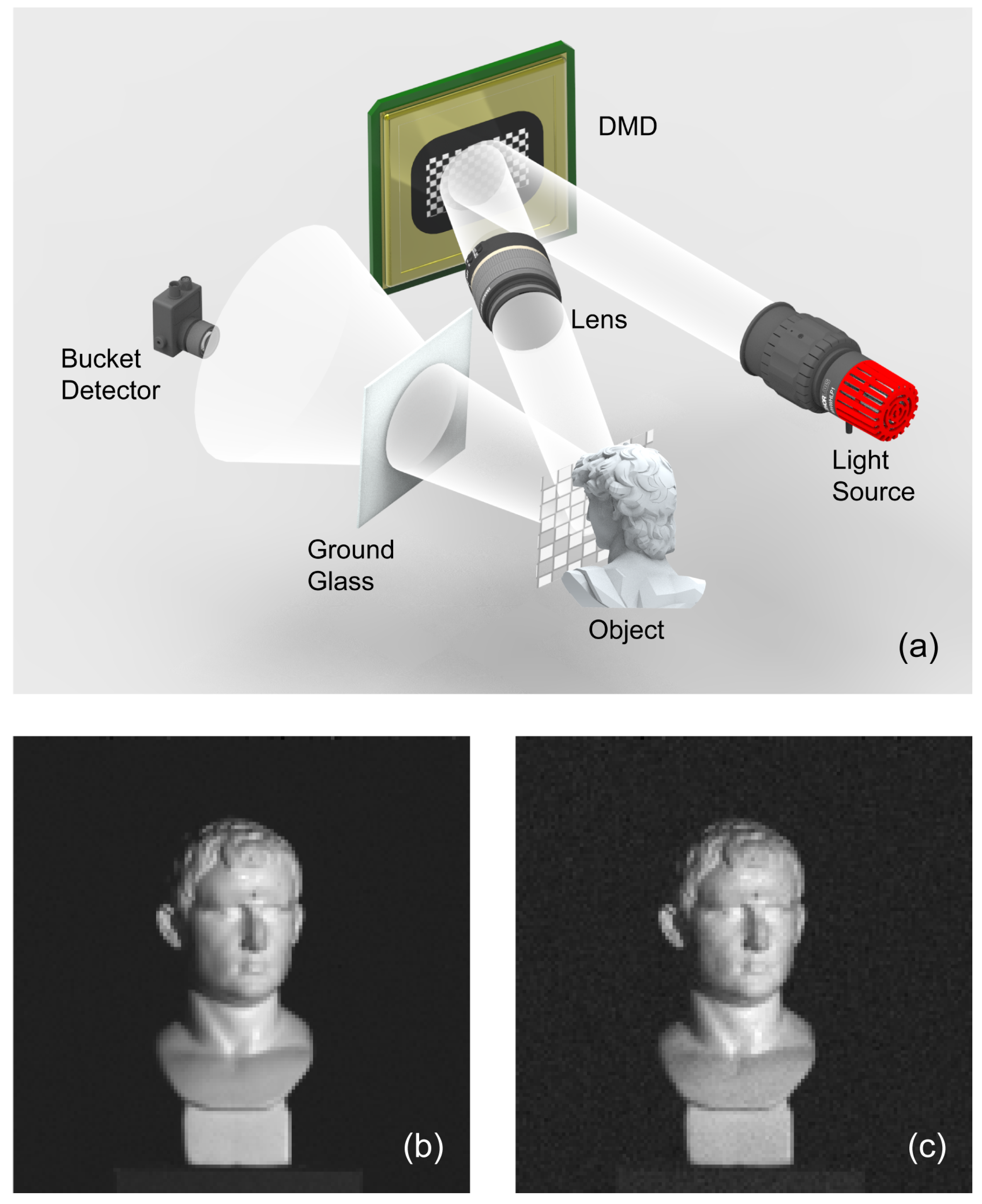
In order to verify the influence of scattering media in detection part on SPI quality, a comparison experiment is carried out.The experimental schematic diagram is shown in Figure 2a. First, an image is obtained with no scattering medium placed in the detection part, that light reflected by the object is directly measured by the bucket detector. SPI result is shown in Figure 2b. In the second imaging process, a sheet of ground glass is placed in the detection part between the object and bucket detector. The light modulated by the object was first scattered through the ground glass and then measured by the bucket detector. Corresponding reconstruction result is shown in Figure 2c.
By comparing Figure 2b,c, we can see that a SPI system can successfully reconstruct the target object even though there are scattering media between the object and bucket detector. However, compared with the result without the scattering medium, the signal-to-noise ratio (SNR) of the reconstructed image with it decreases. Especially when we observe the background part of Figure 2b,c, the phenomenon of relative low SNR of SPI result with scattering media is more significant. One reason is that light is attenuated in the ground glass. More importantly, the ground glass scatters light into random directions. The irradiance of light incident over the photosensitive surface of the bucket detector diminishes, resulting in reduction of signal power. Whereas, the detector noise, such as dark noise or shot noise, does not change. As a consequence, the SNR of reconstructed image decreases. This experiment shows that a reasonable image can be reconstructed by SPI system even with the present of strong scattering media in the detection part, at the cost of the image SNR.

3.2. SPI with FOV Restricted Detection

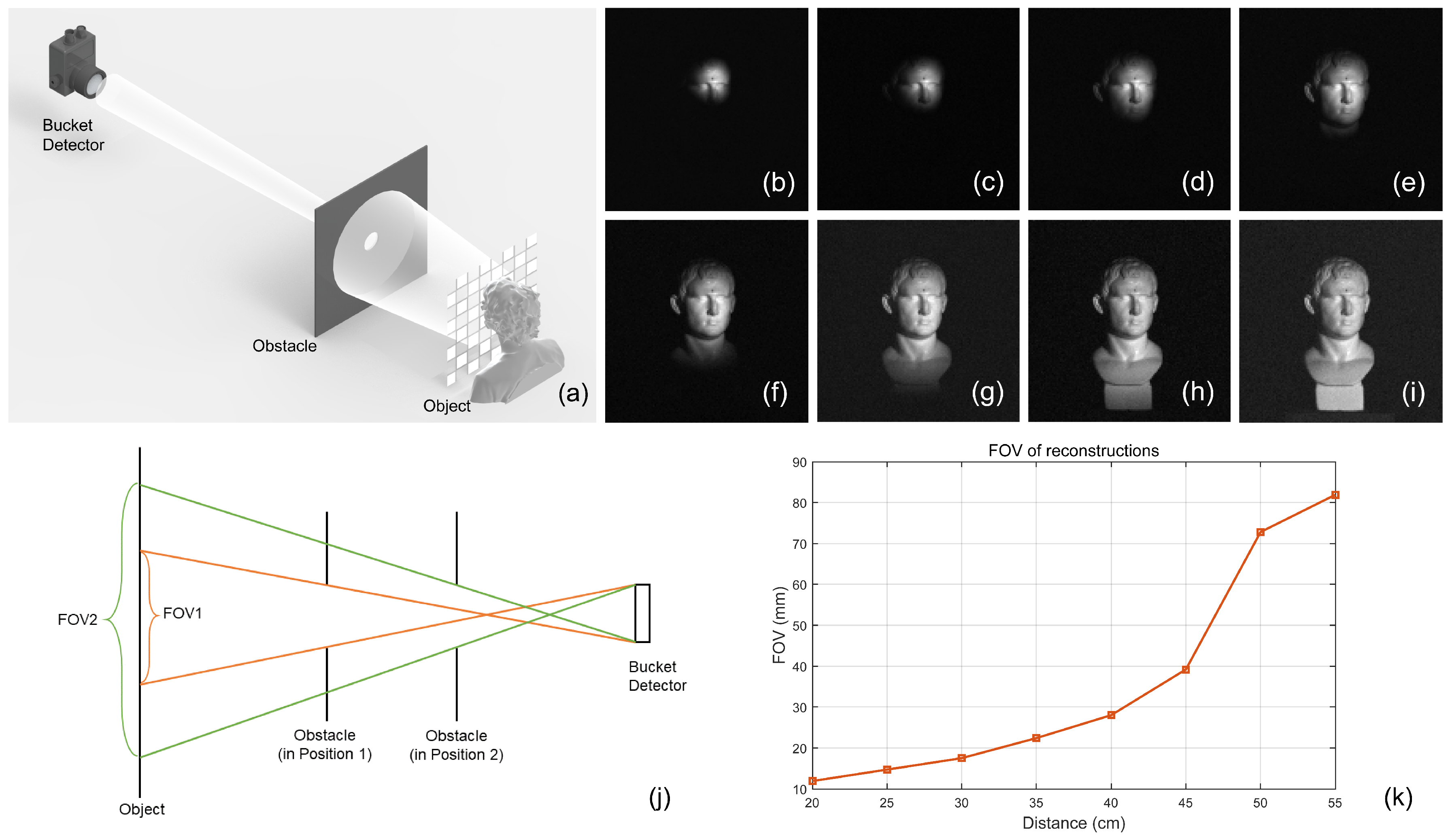
In this section, we will show that, apart from scattering media, obstacles such as an iris in the detection part can affect SPI in a different and more apparent way. In the detection part of SPI system, rather than inserting a sheet of ground glass, we place an obstacle, a 3D-printed circular iris with a diameter of 1 cm, between the object and detector (Figure 3a). Part of the diffusive reflection light from the object can be detected by the bucket detector, while the rest is blocked by the iris. The iris is first placed 20 cm away from the object, where the distance between the object and bucket detector is 60 cm. Imaging results are shown in Figure 3b. Apparently the imaging FOV is highly restricted. To understand this result, we should first remind ourselves that the diffraction of the iris with a diameter of 1 cm is weak and can be ignored. Influence of the iris over the imaging results can be analyzed with geometry optics, that light travels from the object to the detector following rectilinear propagation. In this propagation process, light detected by the detector is direction selective. For a certain point of the object, although diffusive reflection light off the object travels towards all directions, only that of the propagation direction within a small solid angle can arrive at the detecting window of the bucket detector, which is defined by the 1 inch convex lens. Without the iris, light from all areas of the object can be detected by the detector. When the iris is inserted, however, light reflected from certain part of the object is totally blocked away from the detection window. The restriction of FOV is then rendered. As illustrated in Figure 3j, the straight line connecting the top end of the detector and bottom end of the iris determines the bottom boundary of the FOV, while that connecting the bottom end of the detector and top end of the iris determines the top boundary of the FOV, which means that the size of the detector window, the iris size and their distance together determines the FOV on the object plane that can be “seen” by the detector.
According to Figure 3j, the reason of the FOV restriction can also be regarded as the “projection” process of the iris. However, we should be careful that this “projection” process is not that light from the object projects the shape of the iris onto the detection plane. Instead, to understand this process, we need to refer to the reciprocity principle between SPI and traditional imaging system, that we replace the bucket detector with a light source. Then under this virtual light source the shape of the iris projected onto the object determines the FOV. If we move the iris away from the object, the FOV should increase. In order to prove the influence of position of the iris over the FOV, we carry out eight different SPI reconstructions by gradually moving the iris away from the object to the detector. Every time the iris is moved by 5 cm. Results are shown in Figure 3b–i. It can be seen that the shape of the FOV is circular that is similar to the shape of the iris. Therefore, the diameter of FOV circle can be used to quantify the linear FOV of each reconstruction, and the quantification result is illustrated in Figure 3k. The x-axis of Figure 3k is the distance between the obstacle and the object. The y-axis is linear FOV. As the iris gets closer to the bucket detector, the restriction on the FOV reduces and the FOV becomes larger. These results are consistent with the “projection” principle described in Figure 3j. This “projection” process is counterintuitive, as although light travels from the object to the detector, the “projection” of the iris which defines the imaging FOV is virtually from the detector to the object plane. This counterintuitive property provides us an important scenario to understand the reciprocity of SPI to traditional imaging.

3.3. FOV Enlarged by Scattered Light

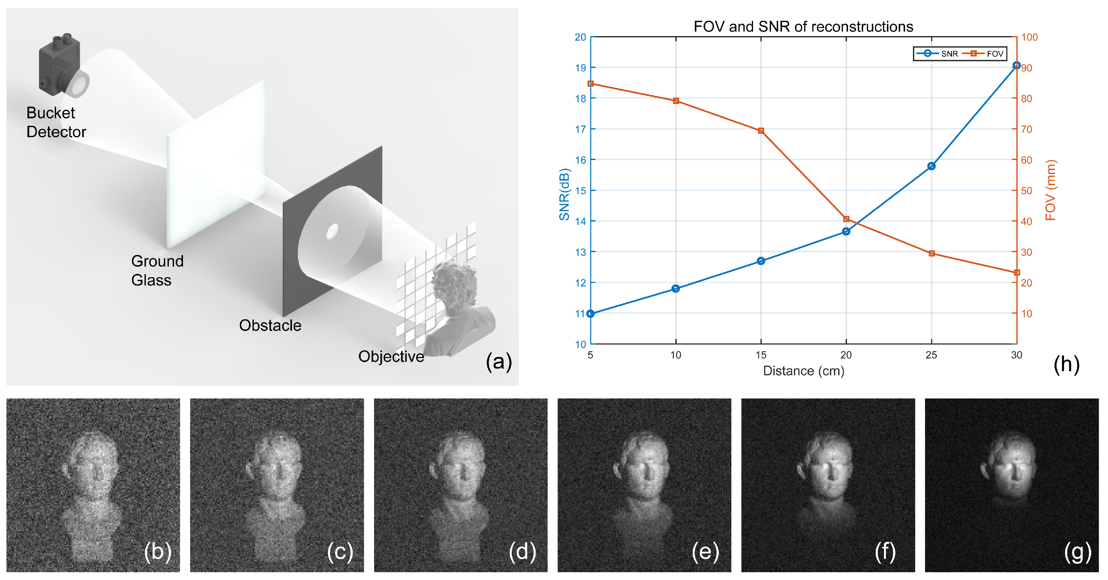
As mentioned above, the incomplete reconstruction shown in Figure 3 is caused by rectilinear propagation of light in homogeneous media (air), while scattering media can change the propagation direction of light without breaking the imaging geometry of SPI. In this case, it is possible that we expand the FOV imposed by the iris by inserting a scattering medium in the detection part to destroy the “projection” process of the iris. To demonstrate this idea, we carry out an experiment by inserting a sheet of ground glass in the detection part of SPI system as shown in Figure 4a. The ground glass used as a scattering medium is placed between the obstacle and the bucket detector. The obstacle is fixed 35 cm away from the object in the detection part, therefore 25 cm from the detector.The position of the obstacle is consistent with Figure 3e. Under structured illumination, object light first passes through the 1 cm iris and then a static ground glass. After scattering, the propagation direction of light changes randomly, generating a larger range of wave vector directions compared to that without scattering.The ground glass is moved from a position clinging to the iris towards the bucket detector with a distance of 5 cm at each movement to explore how the distance between ground glass and the iris affects the of the FOV and the imaging results are shown in Figure 4b–g. By comparing these reconstructions with that shown as Figure 3e, we can see that the FOV of the SPI system, which is restricted by the iris, gets enlarged by inserting the ground glass, but at the same time, SNR is reduced.
To quality the evolution of reconstructions in this process, we calculate the SNR and FOV of each image of Figure 4b–g. FOV is evaluated in the same way as above. SNR is calculated by using Figure 3e as a reference image, because Figure 3e is obtained under the same obstacle arrangement as that in Figure 4. Using Figure 3e the reference image, SNR is calculated as
S N R = 10 log 10 x y R 2 ( x , y ) x y R ( x , y ) T ( x , y ) 2 ,
where T ( x , y ) is the test image, and R ( x , y ) represents Figure 3e as the reference image. As the FOV of reconstructions changes, we use the FOV in the reference image to define the effective area in all images for SNR evaluation. An evaluation of both FOV and SNR is shown in Figure 4h. The x-axis is the distance between ground glass and obstacle. The y-axis in the left and right is SNR and FOV respectively. Each circle marker in the blue line indicates the SNR of a reconstructed image and the square markers in the orange line indicate FOV. The graph manifests an obvious tradeoff between imaging FOV and SNR. With the ground glass moving from the obstacle towards bucket detector, FOV gets enlarged while SNR is reduced. Additionally, by comparing Figure 4b with Figure 2b, we can see that when the ground glass clings to the iris, the FOV is enlarged to a maximum scale, that no FOV restriction can be really noticed. On the other hand, when the ground glass clings to the bucket detector (Figure 4g) the FOV is almost the same as that without ground glass.
The underlying principle can be further understood according to Figure 5. As shown in Figure 5a, the present of the iris blocks point “A” on the object plane from the FOV of SPI system. The red solid line in Figure 5a indicates light from point “A” in certain propagation direction that passes through the iris. Without the ground glass, it travels along straight direction (red dash line) thus can not be detected by the detector. When ground glass is inserted, this light beam gets scattered(blue solid lines in Figure 5a), part of the scattered light then arrives at the detector. In this scenario, if we ignore the attenuation of light in the scattering process, the size of detection window is actually the size of the ground glass. FOV of the SPI system is therefore determined by the iris, the ground glass and their distances to the object plane. Referring to Figure 3j and replacing the detector by the ground glass, we can explain why the FOV reduces when ground glass is moved away from the iris. In practical experiment, however, although FOV is enlarged, light attenuation due to the scattering is nontrivial and causes the reduction of imaging SNR. The scattering attenuation of light power happens in the propagation process from the ground glass to the detector, and aggravates as the traveling distance increases. Thus we can see there is a tradeoff between the imaging FOV and SNR. Figure 5b shows a reciprocal process that illumination area gets enlarged in a traditional imaging system (as we assume that the FOV is primarily limited by the illumination, the array camera is ignored in the figure).
To summarize, we have demonstrated how an obstacle in the detection part of SPI can render the restriction of FOV. We explain this phenomenon using geometry optics together with the reciprocity property of SPI to traditional imaging system with array cameras. The restriction of FOV can be understood as the projection of the obstacle. However, it is important that this projection process needs to be explained with the reciprocity principle. While light in SPI system travels from the object to the detector, the projection of the obstacle that restricts the FOV should be regarded as from the detector to the object. This back-projection property provides an important insight to understand the reciprocity between SPI and traditional imaging. We then show that scattering can diminish this FOV restriction at the cost of imaging SNR.

4. Conclusions

As a new imaging technology, SPI has been widely studied in recent years. The strategy of SPI is to conduct correlation measurement between illumination patterns and the corresponding intensity values measured by a single-pixel detector. Its special imaging modality renovates our understanding about imaging system, meanwhile makes it possible for the new imaging scenario. In this work, we investigate and demonstrate the property of SPI when detection is interrupted by scattering and obstacle aperture. We first prove that scattering media in the detection part of a SPI system only reduces the SNR of imaging to some degree, but will not destroy the imaging geometry or spatial information retrieval of the target object. Meanwhile, we have also shown that obstacles such as an aperture can clearly influence SPI in terms of imaging FOV. We also explain, simply under geometry optics, the principle of this FOV restriction by referring to the reciprocity between SPI and traditional imaging technology using array camera. We have further proposed and demonstrated that this FOV restriction in the detection part of SPI can be overcome by introducing scattering process around the obstacle. This FOV enlargement can also be understood under geometry optics. We believe this study provides us an insight investigation of the property of SPI, especially its reciprocity to traditional imaging systems. It will help us have a better understanding of SPI. Besides, our method to enlarge FOV by using scattering media may provide a new idea to deal with adverse imaging situation.

Author Contributions

Funding acquisition, B.S.; Investigation, P.L. and H.Z.; Methodology, P.L.; Software, H.Z. and W.J.; Validation, P.L. and Z.Z.; Visualization, P.L.; Writing—original draft, P.L.; Writing—review and editing, B.S. All authors have read and agreed to the published version of the manuscript.

Funding

This research was funded by Shandong Joint Funds of Natural Science grant number ZR2019LLZ003-1, Shandong Key Research and Development Program grant number 2019GGX104002 and 2020CXGC010104, Shandong University Inter-discipline Research Grant.

Institutional Review Board Statement

Not applicable.

Informed Consent Statement

Not applicable.

Data Availability Statement

The relevant data are available from the corresponding author upon reasonable request.

Conflicts of Interest

The authors declare no conflict of interest.

References

  1. Pittman, T.B.; Shih, Y.; Strekalov, D.; Sergienko, A.V. Optical imaging by means of two-photon quantum entanglement. Phys. Rev. A 1995, 52, R3429. [Google Scholar] [CrossRef] [PubMed]
  2. Bennink, R.S.; Bentley, S.J.; Boyd, R.W. “Two-photon” coincidence imaging with a classical source. Phys. Rev. Lett. 2002, 89, 113601. [Google Scholar] [CrossRef] [PubMed] [Green Version]
  3. Valencia, A.; Scarcelli, G.; D’Angelo, M.; Shih, Y. Two-photon imaging with thermal light. Phys. Rev. Lett. 2005, 94, 063601. [Google Scholar] [CrossRef] [PubMed] [Green Version]
  4. Shapiro, J.H. Computational ghost imaging. Phys. Rev. A 2008, 78, 061802. [Google Scholar] [CrossRef]
  5. Sun, B.; Edgar, M.P.; Bowman, R.; Vittert, L.E.; Welsh, S.; Bowman, A.; Padgett, M.J. 3D computational imaging with single-pixel detectors. Science 2013, 340, 844–847. [Google Scholar] [CrossRef] [Green Version]
  6. Sun, M.J.; Edgar, M.P.; Gibson, G.M.; Sun, B.; Radwell, N.; Lamb, R.; Padgett, M.J. Single-pixel three-dimensional imaging with time-based depth resolution. Nat. Commun. 2016, 7, 12010. [Google Scholar] [CrossRef]
  7. Ma, Y.; Yin, Y.; Jiang, S.; Li, X.; Huang, F.; Sun, B. Single pixel 3D imaging with phase-shifting fringe projection. Opt. Lasers Eng. 2021, 140, 106532. [Google Scholar] [CrossRef]
  8. Jiang, W.; Li, X.; Peng, X.; Sun, B. Imaging high-speed moving targets with a single-pixel detector. Opt. Express 2020, 28, 7889–7897. [Google Scholar] [CrossRef]
  9. Xu, Z.H.; Chen, W.; Penuelas, J.; Padgett, M.; Sun, M.J. 1000 fps computational ghost imaging using LED-based structured illumination. Opt. Express 2018, 26, 2427–2434. [Google Scholar] [CrossRef] [Green Version]
  10. Sun, S.; Gu, J.H.; Lin, H.Z.; Jiang, L.; Liu, W.T. Gradual ghost imaging of moving objects by tracking based on cross correlation. Opt. Lett. 2019, 44, 5594–5597. [Google Scholar] [CrossRef]
  11. Gibson, G.M.; Sun, B.; Edgar, M.P.; Phillips, D.B.; Hempler, N.; Maker, G.T.; Malcolm, G.P.; Padgett, M.J. Real-time imaging of methane gas leaks using a single-pixel camera. Opt. Express 2017, 25, 2998–3005. [Google Scholar] [CrossRef]
  12. Edgar, M.P.; Gibson, G.M.; Bowman, R.W.; Sun, B.; Radwell, N.; Mitchell, K.J.; Welsh, S.S.; Padgett, M.J. Simultaneous real-time visible and infrared video with single-pixel detectors. Sci. Rep. 2015, 5, 10669. [Google Scholar] [CrossRef]
  13. Jiang, W.; Jiao, J.; Guo, Y.; Chen, B.; Wang, Y.; Sun, B. Single-pixel camera based on a spinning mask. Opt. Lett. 2021, 46, 4859–4862. [Google Scholar] [CrossRef] [PubMed]
  14. Zhang, J.; Wang, Q.; Dai, J.; Cai, W. Demonstration of a cost-effective single-pixel UV camera for flame chemiluminescence imaging. Appl. Opt. 2019, 58, 5248–5256. [Google Scholar] [CrossRef] [PubMed]
  15. Chan, W.L.; Charan, K.; Takhar, D.; Kelly, K.F.; Baraniuk, R.G.; Mittleman, D.M. A single-pixel terahertz imaging system based on compressed sensing. Appl. Phys. Lett. 2008, 93, 121105. [Google Scholar] [CrossRef] [Green Version]
  16. Shrekenhamer, D.; Watts, C.M.; Padilla, W.J. Terahertz single pixel imaging with an optically controlled dynamic spatial light modulator. Opt. Express 2013, 21, 12507–12518. [Google Scholar] [CrossRef]
  17. Stantchev, R.I.; Sun, B.; Hornett, S.M.; Hobson, P.A.; Gibson, G.M.; Padgett, M.J.; Hendry, E. Noninvasive, near-field terahertz imaging of hidden objects using a single-pixel detector. Sci. Adv. 2016, 2, e1600190. [Google Scholar] [CrossRef] [Green Version]
  18. Greenberg, J.; Krishnamurthy, K.; Brady, D. Compressive single-pixel snapshot x-ray diffraction imaging. Opt. Lett. 2014, 39, 111–114. [Google Scholar] [CrossRef]
  19. Pelliccia, D.; Rack, A.; Scheel, M.; Cantelli, V.; Paganin, D.M. Experimental x-ray ghost imaging. Phys. Rev. Lett. 2016, 117, 113902. [Google Scholar] [CrossRef] [Green Version]
  20. Klein, Y.; Schori, A.; Dolbnya, I.; Sawhney, K.; Shwartz, S. X-ray computational ghost imaging with single-pixel detector. Opt. Express 2019, 27, 3284–3293. [Google Scholar] [CrossRef] [Green Version]
  21. Zhang, Z.; Liu, S.; Peng, J.; Yao, M.; Zheng, G.; Zhong, J. Simultaneous spatial, spectral, and 3D compressive imaging via efficient Fourier single-pixel measurements. Optica 2018, 5, 315–319. [Google Scholar] [CrossRef]
  22. Bian, L.; Suo, J.; Situ, G.; Li, Z.; Fan, J.; Chen, F.; Dai, Q. Multispectral imaging using a single bucket detector. Sci. Rep. 2016, 6, 24752. [Google Scholar] [CrossRef] [PubMed] [Green Version]
  23. Hahn, J.; Debes, C.; Leigsnering, M.; Zoubir, A.M. Compressive sensing and adaptive direct sampling in hyperspectral imaging. Digit. Signal Process. 2014, 26, 113–126. [Google Scholar] [CrossRef]
  24. Yi, Q.; Heng, L.Z.; Liang, L.; Guangcan, Z.; Siong, C.F.; Guangya, Z. Hadamard transform-based hyperspectral imaging using a single-pixel detector. Opt. Express 2020, 28, 16126–16139. [Google Scholar] [CrossRef] [PubMed]
  25. Zhang, P.; Gong, W.; Shen, X.; Han, S. Correlated imaging through atmospheric turbulence. Phys. Rev. A 2010, 82, 033817. [Google Scholar] [CrossRef] [Green Version]
  26. Dixon, P.B.; Howland, G.A.; Chan, K.W.C.; O’Sullivan-Hale, C.; Rodenburg, B.; Hardy, N.D.; Shapiro, J.H.; Simon, D.; Sergienko, A.; Boyd, R.; et al. Quantum ghost imaging through turbulence. Phys. Rev. A 2011, 83, 051803. [Google Scholar] [CrossRef] [Green Version]
  27. Leihong, Z.; Zhixiang, B.; Hualong, Y.; Zhaorui, W.; Kaimin, W.; Dawei, Z. Restoration of Single pixel imaging in atmospheric turbulence by Fourier filter and CGAN. Appl. Phys. B 2021, 127, 45. [Google Scholar] [CrossRef]
  28. Jauregui-Sánchez, Y.; Clemente, P.; Lancis, J.; Tajahuerce, E. Single-pixel imaging with Fourier filtering: Application to vision through scattering media. Opt. Lett. 2019, 44, 679–682. [Google Scholar] [CrossRef] [Green Version]
  29. Soltanlou, K.; Latifi, H. Three-dimensional imaging through scattering media using a single pixel detector. Appl. Opt. 2019, 58, 7716–7726. [Google Scholar] [CrossRef]
  30. Seow, K.L.C.; Török, P.; Foreman, M.R. Single pixel polarimetric imaging through scattering media. Opt. Lett. 2020, 45, 5740–5743. [Google Scholar] [CrossRef]
  31. Deng, H.; Wang, G.; Li, Q.; Sun, Q.; Ma, M.; Zhong, X. Transmissive Single-Pixel Microscopic Imaging through Scattering Media. Sensors 2021, 21, 2721. [Google Scholar] [CrossRef] [PubMed]
  32. Brown, R.H. A test of a new type if stellar interferometer on sirius. Nature 1956, 178, 1046–1048. [Google Scholar] [CrossRef]
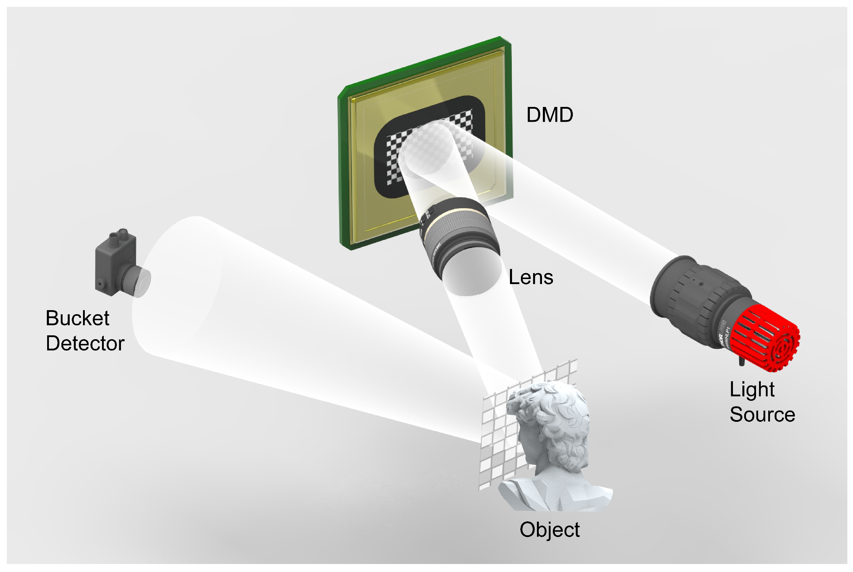
Figure 1. Schematic diagram of an SPI system. In an SPI system, DMD is illuminated by a light source such as an LED or collimated laser beam to produce illumination patterns, which are then projected to object through imaging lens. After interaction with the object, light is measured by a bucket detector. The image can be retrieved by a correlation calculation between illumination patterns and the corresponding detection values.
Photonics 09 00253 g001
Figure 2. (a) Schematic diagram of imaging through scattering media based on SPI. The light source is a white light LED. An amplified photodiode with a 1 inch convex lens is used as the bucket detector. When considering the influence of scattering media on SPI, a sheet of ground glass will be placed in detection part. In all reconstructions throughout this work, imaging resolution is set as 128 × 128 pixels. (b) SPI result of object with no scattering medium in the detection part. (c) SPI result of object when a sheet of ground glass is placed in the detection part between the object and the bucket detector.
Photonics 09 00253 g002
Figure 3. (a) Schematic diagram of detection part in FOV restricted detection. The distance between object and bucket detector is 60 cm. A 3D-printed circular iris in a diameter of 1 cm is used as an obstacle and placed in detection part to restrict FOV. (bi) The reconstructions of gradually moving the obstacle away from the object to the detector, and the distance of every movement is 5 cm. (b) is the reconstructed image when the obstacle is 20 cm away from the object. (i) is the result with the distance between object and obstacle is 55 cm, which indicate that when obstacle clings to bucket detector. (j) Illustration of restricted FOV caused by obstacle in detection part. Orange solid line and Green solid line indicates the FOV determined by the detector and the obstacle in position 1 and position 2, respectively. (k) The linear FOV of reconstructions with respect to the distance between the obstacle and the object.
Photonics 09 00253 g003
Figure 4. (a) Schematic diagram of detection part which enlarges the restricted FOV of SPI by scattered light. FOV is restricted by the iris of 1cm diameter, which is placed 35 cm away from the object in the detection part and therefore 25 cm from the detector. Ground glass is inserted between the iris and bucket detector to generate scattered light. The ground glass is moved from a position clinging to the iris towards the bucket detector with a distance of 5 cm at each movement. (bg) The reconstructions of gradually moving the ground glass away from the iris to bucket detector and the distance of every movement is 5 cm. (b) is the result when the ground glass clings to the iris. (g) is the result when the ground glass clings to bucket detector. (h) The SNR and linear FOV of reconstructions with respect to the distance between ground glass and obstacle.
Photonics 09 00253 g004
Figure 5. (a) Illustration of the FOV enlarged in a SPI system. Orange solid line indicates the FOV determined by the detector size, obstacle size and their distances to the object without the present of ground glass. Red solid line in indicates light from point “A” in certain propagation direction that passes through the iris, and red dash line indicates its original propagation direction without scattering. Blue lines represent scattered light of the incident light from point “A”. (b) Illustration of the FOV enlarged in a traditional imaging system that is in a reciprocal relationship to SPI (as we assume that the FOV is primarily limited by the illumination, the array camera is ignored in the figure). Orange solid line indicates the FOV determined by light source size, obstacle size and their distances to the object without the present of ground glass. Red solid line indicates light from top end of light source in certain propagation direction, and red dash line indicates its original propagation direction without scattering. Blue lines represent scattered light of light from the top end of light source, and part of it can propagate through the obstacle and illuminate point “A”, which means that FOV is enlarged.
Photonics 09 00253 g005
Publisher’s Note: MDPI stays neutral with regard to jurisdictional claims in published maps and institutional affiliations.