Eight-Channel LAN WDM (De)Multiplexer Based on Cascaded Mach–Zehnder Interferometer on SOI for 400GbE

 , ,
, ,
Abstract
1. Introduction
2. Design and Fabrication
3. Device Characterization
4. Conclusions
Author Contributions
Funding
Data Availability Statement
Conflicts of Interest
Abbreviations
| MZI | Mach–Zehnder interferometer |
| LAN | Local Area Network |
| WDM | Wavelength Division Multiplexing |
| MMI | multi-mode interference |
| AWG | arrayed-waveguide grating |
| EDG | echelle diffraction grating |
| CWDM | Coarse Wavelength Division Multiplexing |
| SiN | silicon nitride |
| PSR | polarization splitter rotator |
| FDE | finite-difference eigenmode |
| EME | eigenmode expansion |
| IL | insertion loss |
| PECVD | plasma-enhanced chemical vapor deposition |
| ASE | amplified spontaneous emission |
| OSA | optical spectrum analyzer |
References
- Brackett, C.A. Dense wavelength division multiplexing networks—Principles and applications. IEEE J. Sel. Areas Commun. 1990, 8, 948–964. [Google Scholar] [CrossRef]
- 200 Gb/s and 400 Gb/s Ethernet Task Force. Available online: http://www.ieee802.org/3/bs/ (accessed on 20 October 2021).
- Akca, B.I.; Doerr, C.R.; Sengo, G.; Worhoff, K.; Pollnau, M.; de Ridder, R.M. Broad-spectral-range synchronized flat-top arrayed-waveguide grating applied in a 225-channel cascaded spectrometer. Opt Express 2012, 20, 18313–18318. [Google Scholar] [CrossRef] [PubMed][Green Version]
- Pathak, S.; Vanslembrouck, M.; Dumon, P.; Thourhout, D.V.; Bogaerts, W. Optimized Silicon AWG With Flattened Spectral Response Using an MMI Aperture. J. Lightw. Technol. 2013, 31, 87–93. [Google Scholar] [CrossRef]
- Shi, W.; Yun, H.; Lin, C.; Greenberg, M.; Wang, X.; Wang, Y.; Fard, S.T.; Flueckiger, J.; Jaeger, N.A.F.; Chrostowski, L. Ultra-compact, flat-top demultiplexer using anti-reflection contra-directional couplers for CWDM networks on silicon. Opt. Express 2013, 21, 6733–6738. [Google Scholar] [CrossRef] [PubMed]
- Oguma, M.; Kitoh, T.; Shibata, T.; Inoue, Y.; Jinguji, K.; Himeno, A.; Hibino, Y. Four-channel flat-top and low-loss filter for wide passband WDM access network. Electron. Lett. 2001, 37, 514–515. [Google Scholar] [CrossRef]
- Horst, F.; Green, W.M.; Assefa, S.; Shank, S.M.; Vlasov, Y.A.; Offrein, B.J. Cascaded Mach-Zehnder wavelength filters in silicon photonics for low loss and flat pass-band WDM (de-)multiplexing. Opt. Express 2013, 21, 11652–11658. [Google Scholar] [CrossRef] [PubMed]
- Jeong, S.H.; Shimura, D.; Simoyama, T.; Horikawa, T.; Tanaka, Y.; Morito, K. Si-nanowire-based multistage delayed Mach-Zehnder interferometer optical MUX/DeMUX fabricated by an ArF-immersion lithography process on a 300 mm SOI wafer. Opt. Lett. 2014, 39, 3702–3705. [Google Scholar] [CrossRef] [PubMed]
- Tao, S.; Huang, Q.; Zhu, L.; Liu, J.; Zhang, Y.; Huang, Y.; Wang, Y.; Xia, J. Athermal 4-channel (de-)multiplexer in silicon nitride fabricated at low temperature. Photonics Res. 2018, 6, 686–691. [Google Scholar] [CrossRef]
- Pan, P.; An, J.; Wang, Y.; Zhang, J.; Wang, L.; Qi, Y.; Han, Q.; Hu, X. Compact 4-channel AWGs for CWDM and LAN WDM in data center monolithic applications. Opt. Laser Technol. 2015, 75, 177–181. [Google Scholar] [CrossRef]
- Mikkelsen, J.C.; Bois, A.; Lordello, T.; Mahgerefteh, D.; Menezo, S.; Poon, J.K.S. Polarization-insensitive silicon nitride Mach-Zehnder lattice wavelength demultiplexers for CWDM in the O-band. Opt. Express 2018, 26, 30076–30084. [Google Scholar] [CrossRef] [PubMed]
- Xu, H.; Liu, L.; Shi, Y. Polarization-insensitive four-channel coarse wavelength-division (de)multiplexer based on Mach-Zehnder interferometers with bent directional couplers and polarization rotators. Opt. Lett. 2018, 43, 1483–1486. [Google Scholar] [CrossRef] [PubMed]
- Xu, H.; Dai, D.; Shi, Y. Low-crosstalk and fabrication-tolerant four-channel CWDM filter based on dispersion-engineered Mach-Zehnder interferometers. Opt. Express 2021, 29, 20617–20631. [Google Scholar] [CrossRef] [PubMed]
- Gao, G.; Chen, D.; Tao, S.; Zhang, Y.; Zhu, S.; Xiao, X.; Xia, J. Silicon nitride O-band (de)multiplexers with low thermal sensitivity. Opt. Express 2017, 25, 12260–12267. [Google Scholar] [CrossRef] [PubMed]
- Hassan, K.; Sciancalepore, C.; Harduin, J.; Ferrotti, T.; Menezo, S.; Bakir, B.B. Toward athermal silicon-on-insulator (de)multiplexers in the O-band. Opt. Lett. 2015, 40, 2641–2644. [Google Scholar] [CrossRef] [PubMed]
- Fujisawa, T.; Takano, J.; Sawada, Y.; Saitoh, K. Low-Loss and Small 2 × 4λ Multiplexers Based on 2 × 2 and 2 × 1 Mach–Zehnder Interferometers With On-Chip Polarization Multiplexing for 400GbE. J. Lightw. Technol. 2021, 39, 193–200. [Google Scholar] [CrossRef]
- Jeong, S.-H. Broadband 1 × 8 channel silicon-nanowire-waveguide WDM filter based on point-symmetric Mach-Zehnder interferometric optical couplers in the O-band spectral regime. OSA Continuum. 2019, 2, 3564–3575. [Google Scholar] [CrossRef]
- Munk, D.; Katzman, M.; Kaganovskii, Y.; Inbar, N.; Misra, A.; Hen, M.; Priel, M.; Feldberg, M.; Tkachev, M.; Bergman, A.; et al. Eight-Channel Silicon-Photonic Wavelength Division Multiplexer With 17 GHz Spacing. IEEE J. Sel. Top. Quant. 2019, 25, 1–10. [Google Scholar] [CrossRef]
- Jeong, S.-H.; Tanaka, Y. Silicon-wire optical demultiplexers based on multistage delayed Mach-Zehnder interferometers for higher production yield. Appl. Opt. 2018, 57, 6474–6480. [Google Scholar] [CrossRef] [PubMed]
- Xu, H.; Shi, Y. Flat-Top CWDM (De)Multiplexer Based on MZI With Bent Directional Couplers. IEEE Photonics Technol. Lett. 2018, 30, 169–172. [Google Scholar] [CrossRef]
- Chang, L.; Gong, Y.; Liu, L.; Li, Z.; Yu, Y. Low-Loss Broadband Silicon-on-Insulator Demultiplexers in the O -Band. IEEE Photonics Technol. Lett. 2017, 29, 1237–1240. [Google Scholar] [CrossRef]


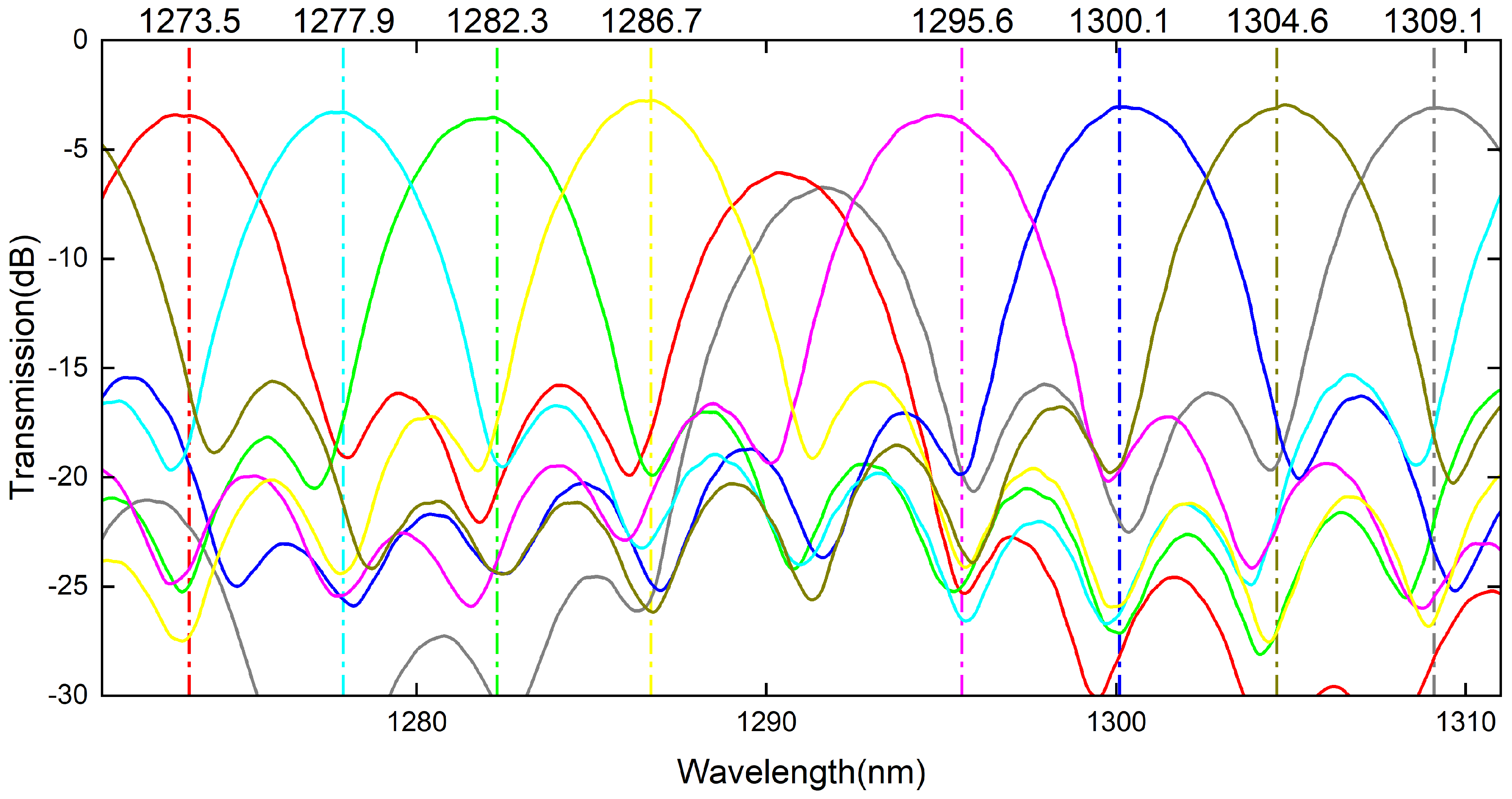
| Lane | Ch1 | Ch2 | Ch3 | Ch4 |
| Wavelength (nm) | 1273.5 | 1277.9 | 1282.3 | 1286.7 |
| Span (nm) | 1272.55–1274.54 | 1276.89–1278.89 | 1281.25–1283.27 | 1258.65–1287.68 |
| Lane | Ch6 | Ch7 | Ch8 | Ch9 |
| Wavelength (nm) | 1295.6 | 1300.1 | 1304.6 | 1309.1 |
| Span (nm) | 1294.53–1296.59 | 1299.02–1301.09 | 1303.54–1305.63 | 1308.09–1310.19 |
| MZIs | Total Length (m) | |
|---|---|---|
| 1st | 48.4 | |
| 2st_A | 24.2 | |
| 2st_B | 24.53 | |
| 3rd_A | 6.05 | |
| 3rd_B | 12.21 | |
| 3rd_C | 12.156 | |
| 3rd_D | 12.264 |
| Lane | Ch1 | Ch2 | Ch3 | Ch4 |
| IL(dB) | −3.45 | −3.30 | −3.57 | −2.77 |
| Crosstalk (dB) | −12.54 | −14.13 | −13.91 | −15.15 |
| Deviation (nm) | −0.4 | 0 | −0.1 | +0.06 |
| Lane | Ch6 | Ch7 | Ch8 | Ch9 |
| IL (dB) | −3.77 | −3.06 | −3.08 | −3.10 |
| Crosstalk (dB) | −16.08 | −16.42 | −14.43 | −15.06 |
| Deviation (nm) | −0.7 | +0.08 | +0.23 | +0.1 |
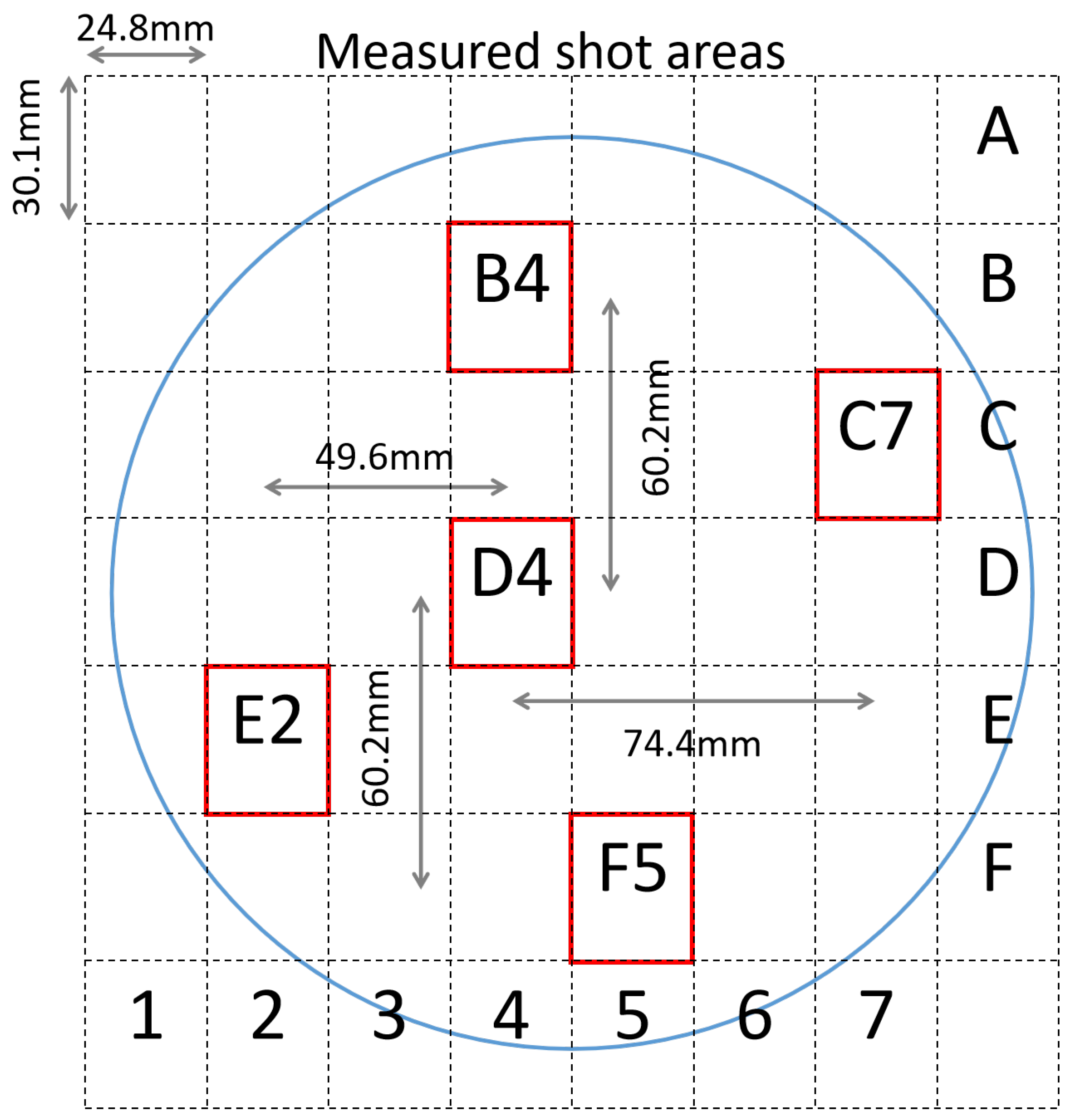
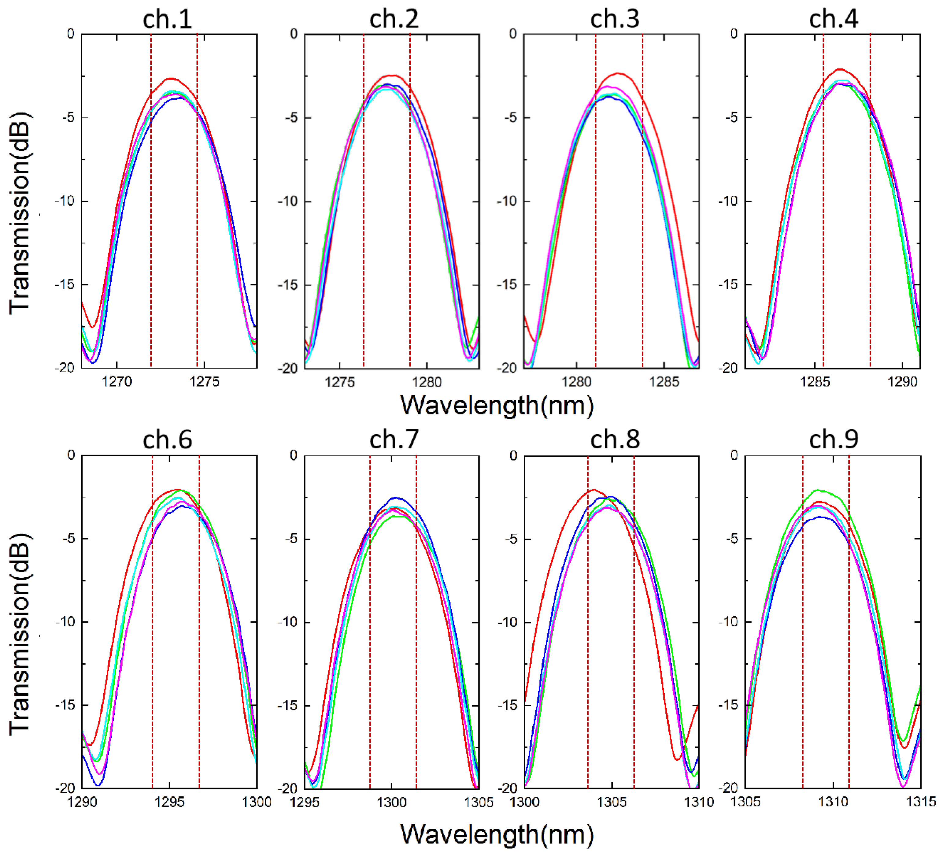
| Lane | IL (dB) | Deviation (nm) | Lane | IL (dB) | Deviation (nm) |
|---|---|---|---|---|---|
| Ch1 | −3.25 ± 0.57 | −0.4∼+0.13 | Ch6 | −2.56 ± 0.5 | −0.07∼+0.12 |
| Ch2 | −2.88 ± 0.42 | −0.32∼−0.05 | Ch7 | −2.60 ± 0.55 | −0.04∼+0.01 |
| Ch3 | −3.13 ± 0.79 | −0.52∼+0.05 | Ch8 | −2.75 ± 0.4 | −0.59∼+0.32 |
| Ch4 | −2.61 ± 0.44 | −0.28∼+0.06 | Ch9 | −2.88 ± 0.8 | −0.02∼+0.14 |
Publisher’s Note: MDPI stays neutral with regard to jurisdictional claims in published maps and institutional affiliations. |
© 2022 by the authors. Licensee MDPI, Basel, Switzerland. This article is an open access article distributed under the terms and conditions of the Creative Commons Attribution (CC BY) license (https://creativecommons.org/licenses/by/4.0/).
Share and Cite
Zhao, Z.; Li, Z.; Niu, J.; Zhang, G.; Chen, H.; Fu, X.; Yang, L. Eight-Channel LAN WDM (De)Multiplexer Based on Cascaded Mach–Zehnder Interferometer on SOI for 400GbE. Photonics 2022, 9, 252. https://doi.org/10.3390/photonics9040252
Zhao Z, Li Z, Niu J, Zhang G, Chen H, Fu X, Yang L. Eight-Channel LAN WDM (De)Multiplexer Based on Cascaded Mach–Zehnder Interferometer on SOI for 400GbE. Photonics. 2022; 9(4):252. https://doi.org/10.3390/photonics9040252
Chicago/Turabian StyleZhao, Zhizun, Zhen Li, Jiaqi Niu, Gaolu Zhang, Hongliang Chen, Xin Fu, and Lin Yang. 2022. "Eight-Channel LAN WDM (De)Multiplexer Based on Cascaded Mach–Zehnder Interferometer on SOI for 400GbE" Photonics 9, no. 4: 252. https://doi.org/10.3390/photonics9040252
APA StyleZhao, Z., Li, Z., Niu, J., Zhang, G., Chen, H., Fu, X., & Yang, L. (2022). Eight-Channel LAN WDM (De)Multiplexer Based on Cascaded Mach–Zehnder Interferometer on SOI for 400GbE. Photonics, 9(4), 252. https://doi.org/10.3390/photonics9040252