Communication

Investigation of the Way of Phase Synchronization of a Self-Injected Bunch and an Accelerating Wakefield in Solid-State Plasma

by
Vasyl I. Maslov
1,2,*,
Denys S. Bondar
1,2 and
Ivan N. Onishchenko
1
1
National Science Centre Kharkov Institute of Physics and Technology, 61108 Kharkiv, Ukraine
2
Department of Plasma Physics, V. N. Karazin Kharkiv National University, 61022 Kharkiv, Ukraine
*
Author to whom correspondence should be addressed.
Photonics 2022, 9(3), 174; https://doi.org/10.3390/photonics9030174
Submission received: 21 November 2021 / Revised: 4 March 2022 / Accepted: 4 March 2022 / Published: 11 March 2022
(This article belongs to the Special Issue Progress in Laser Accelerator and Future Prospects)

Abstract

:
The electron acceleration, in a laser wakefield accelerator, controlled through plasma density inhomogeneity is studied on a basis of 2.5-dimensional particle-in-cell simulation. The acceleration requires a concordance of the density scale length and shift of the accelerated electron bunch relative to wake bubble during electron acceleration. This paper considers the excitation of a wakefield in plasma with a density equal to the density of free electrons in metals, solid-state plasma (the original idea of Prof. T. Tajima), in the context of studying the wakefield process. As is known in the wake process, as the wake bubble moves through the plasma, the self-injected electron bunch shifts along the wake bubble. Then, the self-injected bunch falls into the phase of deceleration of the wake wave. In this paper, support of the acceleration process by maintaining the position of the self-injected electron bunch using an inhomogeneous plasma is proposed. It is confirmed that the method of maintaining phase synchronization proposed in the article by using a nonuniform plasma leads to an increase in the accelerating gradient and energy of the accelerated electron bunch in comparison with the case of self-injection and acceleration in a homogeneous plasma.

1. Introduction

According to the general principles of wakefield acceleration, when a laser pulse is injected into a plasma, a charge separation is formed and a longitudinal accelerating field is excited. The formation of self-injected bunches in regions of increased electron density is also observed (see [1,2,3,4,5,6]). The plasma electrons are spontaneously injected into the wakefield due to a wave-breaking (see [4,5,6]). When a wakefield is excited in a solid-state density plasma by an X-ray laser pulse, both an increase in the accelerating gradient and an increase in the density of self-injected bunches are observed. Previously, the process of wakefield acceleration in high-density plasma by X-ray laser pulses was investigated [7,8]. It was shown that self-injected bunches are formed, and the amplitude of the longitudinal acceleration field reaches several teravolts per meter [9] in accordance with analytical estimates, obtained with the formula (see [10,11]). In this paper, the process of wakefield excitation in plasma is investigated by numerical simulation using the UMKA code [12]. Wake acceleration is a powerful tool for achieving high accelerating gradients, but often requires specific conditions—for example, significant acceleration rates are possible in a capillary at laser powers of 0.5 PW. Moreover, the excitation of the wakefield in capillaries was investigated [13,14]. It was shown that in a solid-state plasma, it is possible to excite fields whose amplitude reaches teravolts per centimeter [15]. It is possible to excite the wakefield in other environments, for example, by a beam in a dielectric, in which the accelerating gradient 13.8 GV/m is achieved [16]. To implement the wakefield acceleration method in a solid-density plasma, new types of lasers are required, which, in many respects, remain a promising idea [17,18]. The excitation of a wakefield in a dielectric was also previously investigated (see [19,20]). When the wakefield is excited by a beam driver, it is possible to effectively excite the wakefield even in the non-resonant case [21,22,23] and provide a high transformer ratio value, which can be approximately defined as the ratio of the maximum accelerating field after the driver to the maximum decelerating field inside the driver (see [24,25]). Thus, the wakefield excitation and acceleration bears great potential for the ability to customize the application for each specific case.
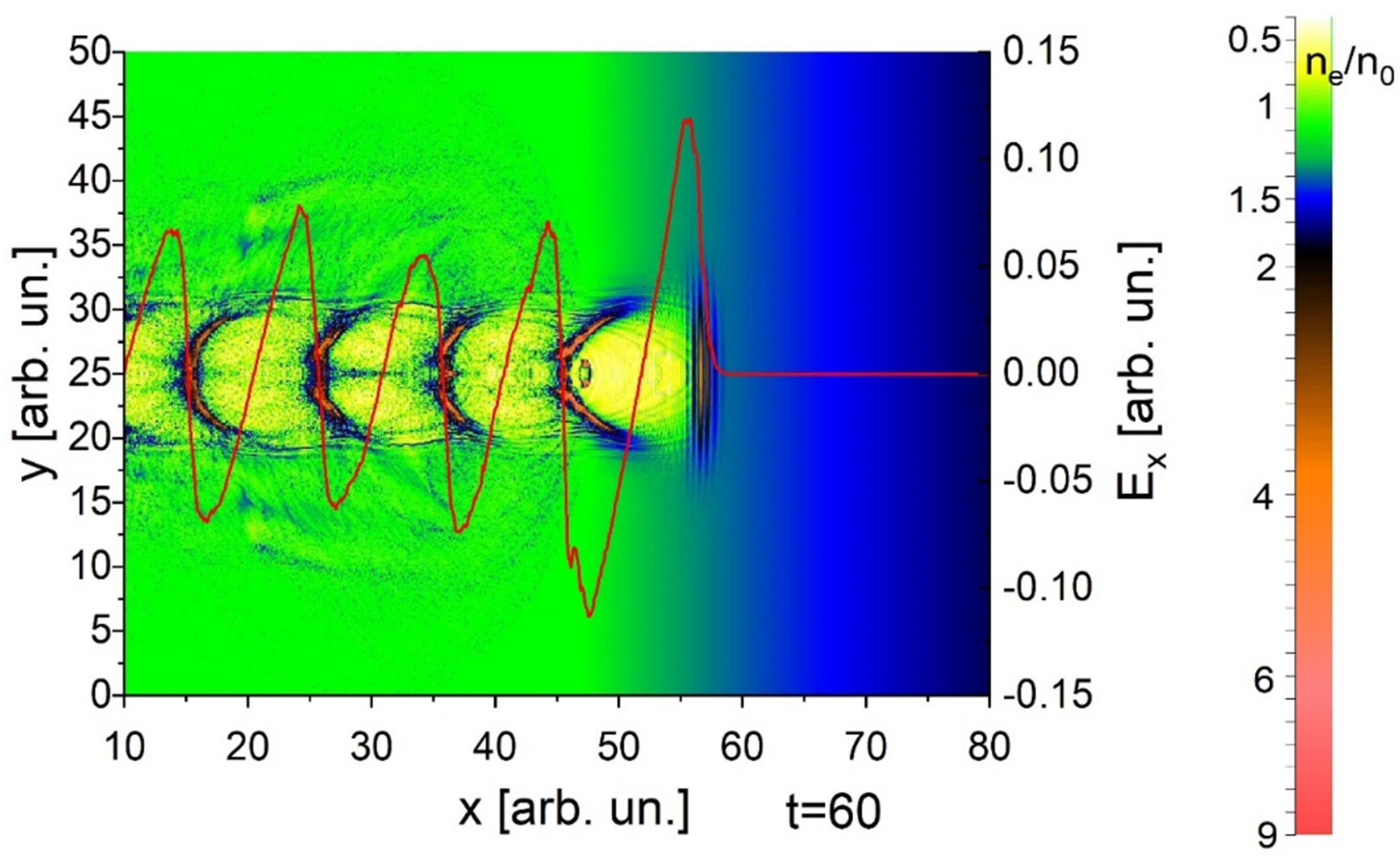
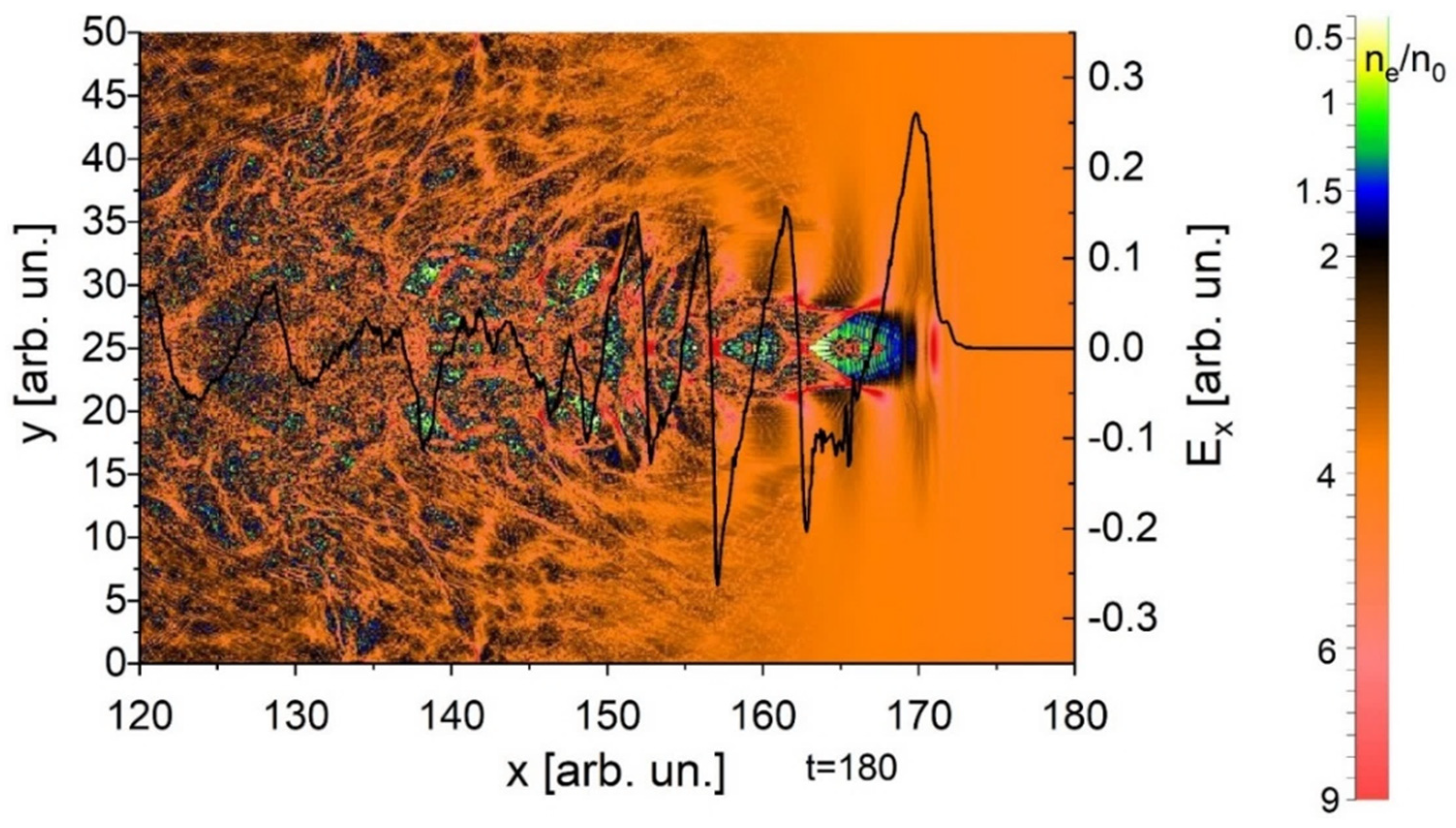
This paper deals with the support of the phase synchronization of the self-injected and accelerated electron bunch and the wake wave through the plasma density inhomogeneity. Two cases are considered. In the first case, the plasma is homogeneous. The wakefield is excited by a single laser pulse. The picture is standard for the wake process: the formation of a wake bubble and a self-injected bunch. The self-injected bunch moves along the wake bubble. At the beginning of its movement (Figure 1) the self-injected bunch is in the acceleration phase, moving to the opposite edge of the wake bubble (Figure 2). Thus, the phase synchronization of the self-injected bunch and the wake wave is violated, leading to the termination of acceleration and subsequent deceleration of the self-injected bunch. The main purpose of this work is to maintain phase synchronization as the self-injected bunch moves. The electron bunch acceleration is considered in solid-state plasma.
At the moment the self-injected bunch reaches approximately middle of the wake bubble, the acceleration ceases. Now let us take into account that in a denser plasma the plasma wavelength is lower and that the leading edge of the wake bubble is associated with the driver. Then, if the driver moves into a denser plasma, the trailing edge of the wake bubble shifts towards the leading edge. Now let us take into account that the maximum accelerating gradient is on the trailing edge of the wake bubble. Then, with a certain choice of plasma density inhomogeneity, the trailing edge moves synchronously with the accelerated bunch, and the accelerated bunch during acceleration is in the area of maximum accelerating gradient. In [1] plasma density inhomogeneity was used to control electron injection into the wake wave. In [2] a negative density gradient with respect to the laser pulse propagation direction and in [3] a positive density gradient were employed at the electron injection into the wake wave. In this paper a density gradient is used to support a synchronization of accelerated electrons with the maximum wakefield phase. Thus, the acceleration requires a concordance of the density scale length and shift of accelerated bunch relative to the wake bubble during electron acceleration. By timely reducing the length of the wake bubble (the length of the wake bubble is equal to the length of the nonlinear plasma wave loaded by driver and witness) one will be able to maintain the self-injected bunch at the trailing edge of the wake bubble in the area of the highest accelerating gradient of the wake bubble. The reduction of the length of the wake bubble occurs owing to a reduction in the length of the plasma wave. This is possible in inhomogeneous plasma. Namely, the plasma density must be increased approximately by a factor of four during the time (at a distance) until the self-injected bunch reaches the middle of the wake bubble.

2. Results of Simulation

The study was carried out through numerical simulation using the UMKA code. The simulation was performed by the PIC method. The electron density of a homogeneous plasma was n 0 = 10 23   c m 3 . All density values are normalized to n 0 . The length of the system in the longitudinal direction is 300 λ and the width of the system is 50 λ in the transverse direction. All lengths and distances are normalized to the laser wavelength λ = 10.65   n m . Laser period is T 0 = c 1 λ = 35.3   a s .
Wakefield amplitude E = aE0 is normalized to E0 = mecω/2πe = 48.08 TV/m, ω l represents the laser frequency. We use frequency ratio approximately equal ω p e ω l 1 = 0.1008 . Excitation of the wakefield by a single laser pulse with an amplitude of a = 3 is considered. FLHM (full length at half maximum) of laser pulse equals 2λ and FWHM (full width at half maximum) equals 8λ. We consider a homogeneous plasma near the injection boundary of a laser pulse in the formation interval of self-injected bunch. When a self-injected bunch is formed, it, together with the driver and bubble, approaches the point of plasma density growth (Figure 3). Moving along the system in an inhomogeneous plasma with increasing density, the self-injected bunch is held in one position at the area of maximum accelerating gradient. As a result, the self-injected bunch is constantly under the action of the accelerating field, without entering the deceleration phase (Figure 4). In the considered homogeneous case, at the moment the self-injected bunch reaches the point x 1 = 47 λ , the self-injected bunch detaches from the wake bubble trailing edge. The bunch reaches the middle of the wake bubble at point x 2 = 167 λ . In the interval from x 1 = 47 λ to the bottom of the system x = 300 λ , the plasma density is inhomogeneous and varies according to the longitudinal distribution n e = n 0 ( ( x 47 λ ) / 40 λ + 1 ) . Consequently, it is possible to reach the plasma density value ne = 4n0 at the point x 2 = 167 λ . Due to this, it is possible to achieve at the point x 2 = 167 λ a two-fold decrease of the plasma wavelength. At the same time, a decrease in the wake bubble length to approximately 60 % of the initial length is observed.
The deviation is explained by the fact that the bubble is nonlinear and its length is greater than the linear plasma wavelength. A comparison of Figure 2 and Figure 5 shows that the amplitude of the accelerating wakefield in the case of an inhomogeneous plasma is 2 times higher than the amplitude in the case of a homogeneous one.
In Figure 2, it can be seen that at the moment when the acceleration process of the self-injected bunch has ceased in the homogeneous case, in the inhomogeneous case (see Figure 5) a significant part of the bunch is accelerated by field of 0.1, which is equal to the initial acceleration field in the homogeneous case. The proposed method for restoring phase synchronization in a laboratory experiment can be implemented, for example, when using multilayer sputtering with different metals. Similar technologies have been widely researched [26].
In Figure 6, one can observe self-injected bunches after about 140 laser periods after the beginning of acceleration in inhomogeneous (a) and homogeneous (b) plasmas. The maximum energy of accelerated electrons in inhomogeneous plasma is 1.7 times higher than in homogeneous plasma. Comparison of Figure 6a,b shows the efficiency of phase synchronization and confinement of the self-injected bunch in the area of high accelerating gradient. Namely, the self-injected and accelerated electron bunch is in the area of high accelerating gradient and is of a higher energy in the case of phase synchronization.

3. Conclusions

During the study, it was shown that the use of a longitudinally inhomogeneous plasma renders it possible to provide phase synchronization of a self-injected bunch and an accelerating longitudinal wakefield, maintaining the self-injected bunch in the area of high accelerating gradient.
The longitudinal distribution according to which the plasma density changes must be developed with the condition, that at the distance that the self-injected bunch shifts, for example, to the middle of the wake bubble in the homogeneous plasma, in the inhomogeneous plasma, the plasma density should increase by a factor of 4 .
The proposed method improves the efficiency of acceleration of the self-injected bunch and leads to an increase in the bunch electron energy.

Author Contributions

Conceptualization, V.I.M., I.N.O.; methodology, V.I.M., D.S.B., I.N.O.; software, D.S.B.; validation, V.I.M., D.S.B., I.N.O.; formal analysis, V.I.M., D.S.B., I.N.O.; investigation, V.I.M., D.S.B.; resources, V.I.M., D.S.B., I.N.O.; data curation, V.I.M., D.S.B., I.N.O.; writing—original draft preparation, V.I.M., D.S.B., I.N.O.; writing—review and editing, V.I.M., D.S.B., I.N.O.; visualization, D.S.B.; project administration, I.N.O.; funding acquisition, V.I.M., D.S.B., I.N.O. All authors have read and agreed to the published version of the manuscript.

Funding

This research received no external funding.

Institutional Review Board Statement

Not applicable.

Informed Consent Statement

Not applicable.

Data Availability Statement

Not applicable.

Acknowledgments

This work is supported by National Research Foundation of Ukraine “Leading and Young Scientists Research Support”, grant agreement # 2020.02/0299.

Conflicts of Interest

The authors declare no conflict of interest.

References

  1. Brantov, A.V.; Esirkepov, T.Z.; Kando, M.; Kotaki, H.; Bychenkov, V.Y.; Bulanov, S.V. Controlled electron injection into the wake wave using plasma density inhomogeneity. Phys. Plasmas 2008, 15, 073111. [Google Scholar] [CrossRef]
  2. Bulanov, S.V.; Naumova, N.; Pegoraro, F.; Sakai, J. Particle injection into the wave acceleration phase due to nonlinear wake wave breaking. Phys. Rev. E 1998, 58, R5257. [Google Scholar] [CrossRef] [Green Version]
  3. Ohkubo, T.; Zhidkov, A.; Hosokai, T.; Kinoshita, K.; Uesaka, M. Effects of density gradient on short-bunch injection by wave breaking in the laser wake field acceleration. Phys. Plasmas 2006, 13, 033110. [Google Scholar] [CrossRef]
  4. Bulanov, S.V.; Inovenkov, I.N.; Kirsanov, V.I.; Naumova, N.M.; Sakharov, A.S. Nonlinear depletion of ultrashort and relativistically strong laser pulses in an underdense plasma. Phys. Fluids B Plasma Phys. 1992, 4, 1935–1942. [Google Scholar] [CrossRef]
  5. Bulanov, S.V.; Pegoraro, F.; Pukhov, A.M.; Sakharov, A.S. Transverse-Wake Wave Breaking. Phys. Rev. Lett. 1997, 78, 4205. [Google Scholar] [CrossRef]
  6. Liseikina, T.V.; Califano, F.; Vshivkov, V.A.; Pegoraro, F.; Bulanov, S.V. Small-scale electron density and magnetic-field structures in the wake of an ultraintense laser pulse. Phys. Rev. E 1999, 60, 5991. [Google Scholar] [CrossRef] [PubMed]
  7. Tajima, T. Laser acceleration in novel media. Eur. Phys. J. Spec. Top. 2014, 223, 1037–1044. [Google Scholar] [CrossRef]
  8. Tajima, T.; Nakajima, K.; Mourou, G. Laser acceleration. La Riv. Nuovo Cim. 2017, 40, 33–133. [Google Scholar]
  9. Bondar, D.S.; Maslov, V.I.; Levchuk, I.P.; Onishchenko, I.N. Excitation of wakefield by a laser pulse in a metallicdensity electron plasma. Probl. At. Sci. Technol. 2018, 6, 156–159. [Google Scholar]
  10. Albert, F.; Couprie, M.E.; Debus, A.; Downer, M.C.; Faure, J.; Flacco, A.; Gizzi, L.A.; Grismayer, T.; Huebl, A.; Joshi, C.; et al. 2020 roadmap on plasma accelerators. New J. Phys. 2021, 23, 031101. [Google Scholar] [CrossRef]
  11. Assmann, R.W.; Weikum, M.K.; Akhter, T.; Alesini, D.; Alexandrova, A.S.; Anania, M.P.; Andreev, N.E.; Andriyash, I.; Artioli, M.; Aschikhin, A.; et al. Eupraxia conceptual design report. Eur. Phys. J. Spec. Top. 2020, 229, 3675–4284. [Google Scholar] [CrossRef]
  12. Dudnikova, G.I.; Liseykina, T.V.; Bychenkov, V.Y. Parallel algorithms for numerical simulation of propagation of an electromagnetic radiation in plasma. Comp. Techn. 2005, 10, 37. [Google Scholar]
  13. Leemans, W.P.; Gonsalves, A.J.; Mao, H.S.; Nakamura, K.; Benedetti, C.; Schroeder, C.B.; Tóth, C.; Daniels, J.; Mittelberger, D.E.; Bulanov, S.S.; et al. Multi-GeV electron beams from capillary-discharge-guided subpetawatt laser pulses in the self-trapping regime. Phys. Rev. Lett. 2014, 113, 245002. [Google Scholar] [CrossRef] [PubMed] [Green Version]
  14. Pieronek, C.V.; Gonsalves, A.J.; Benedetti, C.; Bulanov, S.S.; Van Tilborg, J.; Bin, J.H.; Swanson, K.K.; Daniels, J.; Bagdasarov, G.A.; Bobrova, N.A.; et al. Laser-heated capillary discharge waveguides as tunable structures for laser-plasma acceleration. Phys. Plasmas 2020, 27, 093101. [Google Scholar] [CrossRef]
  15. Hakimi, S.; Nguyen, T.; Farinella, D.; Lau, C.K.; Wang, H.Y.; Taborek, P.; Dollar, F.; Tajima, T. Wakefield in solid state plasma with the ionic lattice force. Phys. Plasmas 2018, 25, 023112. [Google Scholar] [CrossRef]
  16. Thompson, M.C.; Badakov, H.; Cook, A.M.; Rosenzweig, J.B.; Tikhoplav, R.; Travish, G.; Blumenfeld, I.; Hogan, M.J.; Ischebeck, R.; Kirby, N.; et al. Breakdown limits on gigavolt-per-meter electron-beam-driven wakefields in dielectric structures. Phys. Rev. Lett. 2008, 100, 214801. [Google Scholar] [CrossRef] [PubMed] [Green Version]
  17. Danson, C.N.; Haefner, C.; Bromage, J.; Butcher, T.; Chanteloup, J.-C.F.; Chowdhury, E.A.; Galvanauskas, A.; Gizzi, L.A.; Hein, J.; Hillier, D.I. Petawatt and exawatt class lasers worldwide. High Power Laser Sci. Eng. 2019, 7, e54. [Google Scholar] [CrossRef]
  18. Kim, T.H.; Pathak, V.B.; Hojbota, C.L.; Mirzaie, M.; Pae, K.H.; Kim, C.M.; Yoon, J.W.; Sung, J.H.; Lee, S.K. Multi-GeV Laser Wakefield Electron Acceleration with PW Lasers. Appl. Sci. 2021, 11, 5831. [Google Scholar] [CrossRef]
  19. Onishchenko, I.N.; Kiselev, V.A.; Linnik, A.F.; Sotnikov, G.V. Concept of dielectric wakefield accelerator driven by a long sequence of electron bunches. In Proceedings of the IPAC, Shanghai, China, 12–17 May 2013; p. 1259, ISBN 978-3-95450-122-9. [Google Scholar]
  20. Onishchenko, I.N.; Kiseljob, V.A.; Berezin, A.K.; Sotnikov, G.V.; Uskov, V.V.; Linnik, A.F.; Fainberg, Y.B. The wake-field excitation in plasma-dielectric structure by sequence of short bunches of relativistic electrons. In Proceedings of the Particle Accelerator Conference, Dallas, TX, USA, 1–5 May 1995; p. 2782. [Google Scholar]
  21. Lotov, K.V.; Maslov, V.I.; Onishchenko, I.N.; Yarovaya, I.P. Mechanisms of synchronization of relativistic electron bunches at wakefield excitation in plasma. Probl. At. Sci. Technol. 2013, 4, 73–76. [Google Scholar]
  22. Lotov, K.V.; Maslov, V.I.; Onishchenko, I.N. Long sequence of relativistic electron bunches as a driver in wakefield method of charged particles acceleration in plasma. Probl. At. Sci. Technol. 2010, 6, 103–107. [Google Scholar]
  23. Bondar, D.S.; Maslov, V.I.; Boychenko, A.P.; Ovsiannikov, R.T.; Onishchenko, I.N. Dependence of wakefield excitation in plasma by non-resonant sequence of electron bunches on their lengths. Probl. At. Sci. Technol. 2021, 4, 65–69. [Google Scholar] [CrossRef]
  24. Lotov, K.V.; Maslov, V.I.; Onishchenko, I.N. Transformation ratio in wake-field method of acceleration for sequence of relativistic electron bunches. Probl. At. Sci. Technol. 2010, 4, 85–89. [Google Scholar]
  25. Baturin, S.S.; Zholents, A. Upper limit for the accelerating gradient in the collinear wakefield accelerator as a function of the transformer ratio. Phys. Rev. Accel. Beams 2017, 20, 061302. [Google Scholar] [CrossRef] [Green Version]
  26. Marzbanrad, B.; Toyserkani, E.; Jahed, H. Characterization of single-and multilayer cold-spray coating of Zn on AZ31B. Surf. Coat. Technol. 2021, 416, 127155. [Google Scholar] [CrossRef]
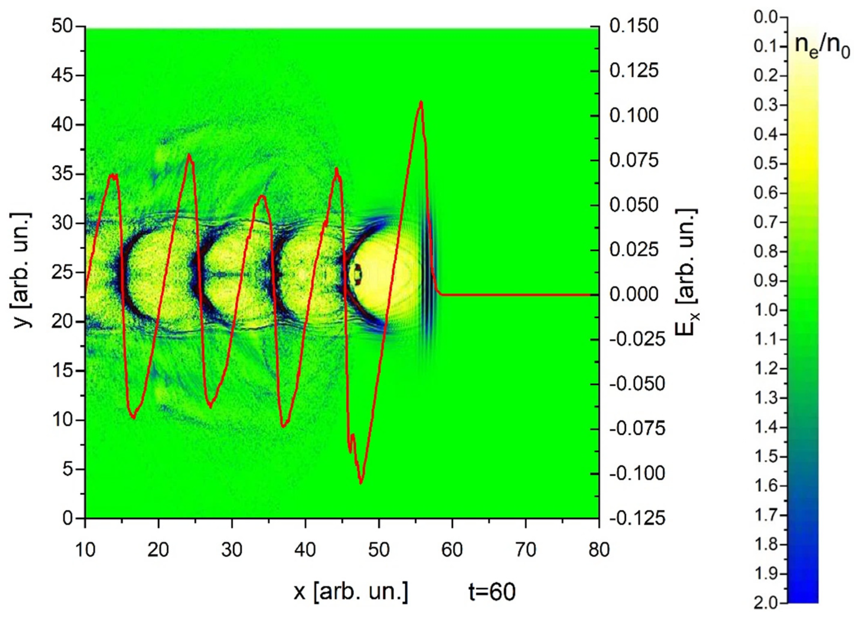
Figure 1. Excitation of a wakefield by a laser pulse in homogeneous plasma t = 60 T 0 . The self-injected bunch is close to the area of maximum accelerating gradient. Separate areas in which the ratio of electron densities reaches a value of 9 are highlighted in red. Plasma electron density and longitudinal accelerating field distributions. x, y are normalized to λ, Ex is normalized to E0 = mecω/2πe.
Photonics 09 00174 g001
Figure 2. Excitation of a wakefield by a laser pulse in homogeneous plasma t = 180 T 0 . The self-injected bunch is close to the middle of the bubble. Separate areas in which the ratio of electron densities reaches a value of 9 are highlighted in red. Plasma electron density and longitudinal accelerating field distributions. x, y are normalized to λ, Ex is normalized to E0 = mecω/2πe.
Photonics 09 00174 g002
Figure 3. Excitation of a wakefield by a laser pulse in inhomogeneous plasma t = 60 T 0 . The self-injected bunch is close to the area of maximum accelerating gradient. Plasma electron density and longitudinal accelerating field distributions. x, y are normalized to λ, Ex is normalized to E0 = mecω/2πe.
Photonics 09 00174 g003
Figure 4. Excitation of a wakefield by a laser pulse in inhomogeneous plasma t = 140 T 0 . The self-injected bunch is close to the area of maximum accelerating gradient. Plasma electron density and longitudinal accelerating field distributions. x, y are normalized to λ, Ex is normalized to E0 = mecω/2πe.
Photonics 09 00174 g004
Figure 5. Excitation of a wakefield by a laser pulse in inhomogeneous plasma t = 180 T 0 . Plasma electron density distribution and longitudinal accelerating field. x, y are normalized to λ, Ex is normalized to E0 = mecω/2πe.
Photonics 09 00174 g005
Figure 6. Distribution of the longitudinal momentum of self-injected bunch in inhomogeneous (a) and homogeneous (b) plasma t = 140 T 0 . px is normalized to mec.
Photonics 09 00174 g006
Publisher’s Note: MDPI stays neutral with regard to jurisdictional claims in published maps and institutional affiliations.