Article

Amplification and Generation of Frequency-Modulated Soliton Pulses in Nonuniform Active Fiber Configurations

1
S.P. Kapitsa Scientific Technological Research Institute, Ulyanovsk State University, 42 Leo Tolstoy Str., 432970 Ulyanovsk, Russia
2
Scientific-Manufacturing Complex “Technological Centre”, Shokin Square, House 1, Bld. 7, Zelenograd, 124498 Moscow, Russia
3
Electromagnetism and Telecommunication Department, University of Mons, B-7000 Mons, Belgium
*
Author to whom correspondence should be addressed.
Photonics 2022, 9(3), 160; https://doi.org/10.3390/photonics9030160
Submission received: 19 January 2022 / Revised: 2 March 2022 / Accepted: 3 March 2022 / Published: 6 March 2022
(This article belongs to the Special Issue Specialty Optical Fibers, Fiber Lasers and Their Applications)

Abstract

:
We report on the theoretical and numerical analysis of the nonlinear Schrödinger equation describing the dynamical evolution of frequency-modulated (FM) optical signals propagating through the fiber configuration comprising active fibers with the anomalous dispersion nonuniformly distributed over the fiber length. In our consideration, a single active fiber section including segments with initially increasing and then decreasing dispersion is used for amplification and compression of an external FM pulse resulting in an increase of ~6 orders of magnitude in the pulse peak power and a 100-fold narrowing of the pulse duration down to a few picoseconds. Moreover, we demonstrate that, with a ~1 mW weakly modulated continuous wave input signal, the fiber configuration comprising two active fiber sections with different dispersion profiles is able to generate a strongly periodic pulse train, resulting in a pulse repetition rate >100 GHz, a pulse duration ~0.5 ps, and peak power up to ~1 kW. An evolution of optical signals governed by modulation instability in both fiber configurations is explored.

1. Introduction

The critical part of laser physics is the development of ultrashort pulse generators (USPs), which provide a high peak radiation power [1,2]. Extremely high concentration of energy, broadband optical spectrum, and extremely short time of light emission [3,4,5] make the ultrashort pulse (USP) of great interest for many applications such as processing and modification of materials, laser micro- and nanostructuring of materials, and nuclear and accelerator technologies [1,2,5,6,7,8,9,10,11]. Furthermore, high-frequency fiber lasers of USP with a repetition rate over 1 GHz are fabulous candidates for the development of radiophotonics technologies [12,13,14].
Despite a solid understanding [3,5,15], USP generation remains a subject of intensive studies and multiple publications [1,2,5,11]. In previous studies [16,17,18], USP generation was demonstrated in fibers with the nonlinear and dispersion parameters nonuniformly distributed over the fiber length. Fibers with slowly decreasing dispersion are promising for nonlinear fiber optics and, in particular, for ultrashort pulse generation and compression [19,20]. A number of optical fiber configurations for amplification and time compression of USP based on nonuniform fibers were proposed in [21,22,23,24]. However, pulse compression down to femtosecond durations has not yet been achieved in all-fiber format. External non-fiber devices like diffraction gratings are commonly used for this purpose [5], making the system less reliable and requiring permanent maintenance.
One of the effects accompanying USP propagation is the modulation instability (MI) that can be employed both for USP generation and control of USP repetition rate [15,25,26,27,28,29]. In this process, the light evolution exhibits periodic behavior. A harmonically modulated input continuous wave (CW) signal transforms into a train of short pulses possessing the period of initial modulation and then transforms back into the modulated CW light approaching the initial signal [15,26,27,28]. The fiber length, within which the input signal is transformed into the pulse train, depends on the initial modulation depth and commonly ranges from one to 10 dispersion lengths [15,30].
Importantly, the peak power of individual soliton-like pulses never significantly exceeds the input signal level. The light evolution dynamics becomes different when a fiber with the group velocity dispersion (GVD) nonuniformly distributed over the length is used. In this case, the generated pulse train could be much higher peak power than the input signal [19,20,31].
In this paper, we consider the mechanism for transforming continuous radiation into high-frequency pulsed radiation with a linear chirp. In addition, we consider multistage schemes that involve not only the formation of high-contrast USPs (with a peak power much higher than the average background radiation power) from CW, but also their further amplification. It is shown below that the generated pulses have a chirp close to linear. This, in turn, opens up the possibility for their further compression (for example, using a pair of “standard” diffraction gratings). In this paper, we explore the ability of active optical fibers with the dispersion parameters distributed over the fiber length to amplify soliton-like pulses and generate USP trains, getting a peak power orders of magnitude higher than that of the input optical signal. In particular, a single active fiber section including fiber segments with increasing and then decreasing anomalous dispersion is shown to enable an amplification and compression of an external FM pulse resulting in an increase of ~6 orders of magnitude in the pulse peak power and a 100-fold narrowing of the pulse duration down to a few picoseconds.
On the basis of these results, the fiber configuration comprising two fiber sections with similar dispersion profiles is demonstrated to generate a strongly periodic pulse train resulting in a pulse repetition rate >100 GHz, a pulse duration of ~0.5 ps, and a peak power of up to 1 kW that is ~5 orders of magnitude higher than the input signal level. In both cases, we explore evolution of optical signals governed by modulation instability.

2. Basic Equations

We consider propagation of a single FM wave packet (WP) in an optical fiber with the GVD nonuniformly distributed over the fiber length. The evolution of pulse envelope A ( t , z ) is described by the nonlinear Schrödinger equation [5].
A z i d 2 ( z ) 2 2 A τ 2 d 3 ( z ) 6 3 A τ 3 + i R ( z ) ( | A | 2 T R | A | 2 τ ) A = γ ( z ) A ,
where d n ( z ) = ( n β ( z ) / ω n ) ω = ω 0 are the dispersion parameters, β is the real part of the complex propagation constant, τ = t 0 z d ξ / u ( ξ ) is the time in the moving reference frame, u ( z ) = ( β ( z ) / ω ) ω = ω 0 1 is the WP group velocity, R ( z ) is the Kerr nonlinearity coefficient, T R is the Raman response time of medium, and γ ( z ) is the effective gain coefficient.
The effective gain coefficient can be expressed as
γ ( z ) = g ( z ) 1 2 S m S m z ,
where g ( z ) is the fiber material gain increment, and the second term in Equation (2) appears due to changes of effective mode area [5].
S m ( z ) = 2 π 0 | U ( r , z ) | 2 r d r ,
where U ( r , z ) is the fiber mode field distribution as a function of the coordinate z along the fiber.
The optical fiber material gain increment g ( z ) is the radially averaged function depending on the mode field profile.
g ( z ) = 2 π k 0 S m 1 ( z ) 0 n ( r , z ) | U ( r , z ) | 2 r d r ,
where k 0 = ω 0 / c , c is the speed of light in vacuum, and n is the imaginary part of the fiber refractive index. Bearing in mind W-shaped fibers, we can assume that nonuniform active fibers with any arbitrary distribution of the second- and even third-order dispersion parameters over the fiber length can be manufactured using an advanced control of fiber diameter during drawing [20,32].
For the WP propagating through a nonuniform active fiber, an increase in its energy is defined by the distribution of the material gain increment over the fiber length g ( z ) as follows:
W ( z ) = W 0 exp ( 2 0 z g ( ξ ) d ξ ) ,
where W 0 is the input pulse energy. The Kerr nonlinearity coefficient reads as follows [5]:
R ( z ) = 2 π k 0 S m 2 ( z ) 0 n ˜ ( r , z ) | U ( r , z ) | 4 r d r ,
where n ˜ is the nonlinear refractive index of the fiber material. Note, for uniform fibers, the linear n and nonlinear n ˜ refractive indices, mode profile U ( r ) , and hence, g and R do not change with z .

3. Amplification of FM Soliton-Like Pulses

In this section, we describe the amplification of soliton-like FM pulses in a single active fiber segment possessing a specific distribution of the GVD over the fiber length. Let us consider first an active fiber with the gain increment varying along the fiber length according to the expression
g ( z ) = g 0 / ( 1 2 g 0 z ) ,
where g 0 is the gain increment at z = 0 .
The anomalous GVD and nonlinearity increment are assumed to be unchangeable over the fiber length, and the terms responsible for the third-order dispersion and Raman process are negligible.
In this case, the analytical solution of Equation (1) (at d 2 R < 0 and 2 g 0 z < 1 ) could be expressed in the form of a soliton-like pulse commonly referred to as a bright FM soliton [3,5].
A ( τ , z ) = A 0 1 2 g 0 z sech ( τ τ s ) exp ( i α 0 τ 2 Γ z 1 2 g 0 z ) ,
where τ s = τ 0 ( 1 2 g 0 z ) is the pulse width, Γ = g 0 / 2 α 0 τ 0 2 , α 0 is the initial pulse chirp, and the parameters are related as 2 Γ = | d 2 | / τ 0 2 = R | A 0 | 2 . Let us now assume that both dispersion and nonlinearity vary with the coordinate z . We can introduce these changes as d 2 ( z ) = d 20 Θ ( z ) and R ( z ) = R 0 r ( z ) , where d 20 and R 0 are the corresponding quantities at the fiber segment input. With the other introduced functions η ( z ) = 0 z Θ ( ξ ) d ξ and C ( τ , z ) = r ( z ) / Θ ( z ) A ( τ , z ) , Equation (1) is reduced to
C η i d 20 2 2 C τ 2 + i R 0 | C | 2 C = γ e f ( η ) C .
In such a way, the problem of pulse propagation in the nonuniform fiber is reduced to the problem of pulse propagation in the fiber with unchangeable dispersion d 20 and nonlinearity R 0 , but with the effective gain increment γ e f ( η ) distributed over the fiber length as
γ e f ( η ) = g ( η ) Θ ( η ) 1 2 η ln σ ( η ) Θ ( η ) r ( η ) ,
where σ = S m ( η ) / S m ( 0 ) is the normalized mode field profile.
Similarly to Equation (1), the analytical solution of Equation (9) (at d 2 ( η ) R ( η ) < 0 and 2 γ e f ( η ) η < 1 ) with the effective gain factor in Equation (10) γ e f ( η ) = q / ( 1 2 q η ) , where q = γ e f ( 0 ) , reads as
C ( τ , η ) = A 0 1 2 q η sech τ τ s exp ( i α 0 τ 2 Γ 0 η 1 2 q η ) ,
where the parameters τ s = τ 0 ( 1 2 q η ) , Γ 0 = q / 2 α 0 τ 0 2 , and q = α 0 | d 20 | are introduced.
As mentioned above, Equation (11) is the solution of Equation (9) under the condition of
γ e f ( η ) = α 0 d 20 1 + 2 α 0 d 20 η = q 1 2 q η .
Taking into account Equations (10) and (12), this can be expressed in the form
( 1 + 2 α 0 d 20 0 z Θ ( ξ ) d ξ ) exp ( 2 0 z g ( ξ ) d ξ ) = Θ ( z ) σ ( z ) / r ( z ) .
From Equation (13), the GVD profile suitable for the formation of a soliton-like pulse is
Θ ( z ) = f ( z ) exp ( 2 q 0 z f ( ξ ) d ξ ) ,
where two functions, f ( z ) = F ( z ) exp ( 2 0 z g ( ξ ) d ξ ) and F ( z ) = r ( z ) σ ( z ) , are introduced.
Correspondingly, the duration and frequency modulation (linear chirp) of FM pulses are expressed as
τ s ( z ) = τ 0 Θ ( z ) F ( z ) exp ( 2 0 z g ( ξ ) d ξ ) = τ 0 exp ( 2 q 0 z f ( ξ ) d ξ ) ,
α ( z ) = α 0 exp ( 2 q 0 z f ( ξ ) d ξ ) .
Let us assume now that the gain increment does not change along the fiber length. If F ( z ) = 1 , and g ( z ) = g 0 , the function f ( z ) = exp ( 2 g 0 z ) and the expressions for the GVD distribution and pulse duration are
d ( z ) = | d 20 | exp [ α 0 | d 20 | g 0 ( exp ( 2 g 0 z ) 1 ) + 2 g 0 z ] ,
τ ( z ) = τ 0 exp [ α 0 | d 20 | g 0 ( exp ( 2 g 0 z ) 1 ) ] .
The made simplifications are reasonable. Indeed, the W-shaped fibers are considered to be suitable candidates for implementation of the discussed mechanisms [20,32]. The W-shaped fibers with almost arbitrary GVD profile can be manufactured using control of fiber diameter during drawing [20]. Moreover, it can be achieved while keeping relatively low level of the third-order dispersion | d 3 | 10 38 s 2 / m and avoiding significant effects on the gain increment and Kerr nonlinear coefficient.
In the case of a low gain limit ( 2 g 0 z 1 ), when exp ( 2 g 0 z ) 1 + 2 g 0 z , Equations (17) and (18) are reduced to
d ( z ) | d 20 | exp ( 2 α 0 | d 20 | z ) ,
τ ( z ) τ 0 exp ( 2 α 0 | d 20 | z ) .
It is worth noting that the condition F = 1 is not always true. The equation F = 1 is right if the Kerr nonlinearity parameter is constant along the fiber length. This is possible if only the effective mode area varies weakly along the fiber length [5]. The condition of a constant nonlinearity parameter of the fiber is incorrect in the case of a tapered fiber with a varying mode area or in the case of an active fiber with nonuniform doping along the fiber length. Thus, F is an additional parameter allowing control over the dynamics of the modulated and amplified wave packet.
However, in contrast to Equation (19), the dispersion profile in Equation (17) combines the ranges with increasing and decreasing GVD. Potentially, it is useful for an enhanced peak power scaling of the propagating FM pulses. In this combination, the fiber length with the increasing GVD enables a stable amplification of the pulse, while the length with decreasing GVD enables both the pulse amplification and the temporal compression of the pulse shape [19,33].
Figure 1a shows the propagation of an FM soliton-like pulse through a single fiber segment with the GVD profile described by Equation (17). The input pulse shape is expressed as
A ( 0 , τ ) = A 0 sech ( τ / τ 0 ) exp ( i α 0 τ 2 ) .
The z 0 position is obtained through the differential from Equation (17) and given by z 0 = ln [ g 0 / ( α 0 | d 20 | ) ] / 2 g 0 . GVD has a maximum at the point z = z 0 (Figure 1a).
The numerical simulation of the pulse propagation in an active fiber segment with the GVD profile described by Equation (17) was simulated with the split-step Fourier method (SSFM method) [5]. The calculation parameters are listed in the Table 1. They satisfy the condition P 0 = | d 20 | / τ 0 2 R 0 at P 0 = 0.01 W .
The distribution of the anomalous GVD along the fiber segment length comprising the ranges with increasing and decreasing GVD values is shown in Figure 1a (curve 1), and in Figure 2 (the first segment l1). It gets its maximum at z = z0 corresponding to dmax ≈ 40d20. The pulse shapes at the fiber segment input and at the point z = z0, and the fiber segment output are shown in Figure 1b (curves 1, 2, and 3, respectively). While propagating in the fiber length with the increasing dispersion z < z 0 ), the FM pulse exhibits a 300-fold increase in its peak power (Figure 1a,b; curves 2). In the fiber length (z > z0), the GVD decreases to almost its initial value (Figure 1a, curve 1), and the amplified soliton-like FM pulse is compressed. Its peak power explosively increases, reaching ~10 kW at the fiber segment output (Figure 1b, curve 3), which is ~6 orders of magnitude higher than its input signal peak power. The optimal length of this fiber range ( z > z 0 ) is determined by the fiber point, where the pulse is still able to keep its shape, as l 2 = 17 . 269 m used in our calculations (Table 1).

4. Induced MI and Generation of FM Soliton-Like Pulse Train

In the previous section, we demonstrated drastic amplification and temporal compression of a soliton FM pulse achieved in an active fiber with nonuniform GVD profile. In this section, we consider the process of soliton-like pulse generation through the modulation instability implemented in a cascade of such fibers.
We assume that a weakly modulated CW optical signal with the power P 0 is used as an input signal.
A ( 0 , τ ) = P 0 [ 1 + m cos ( Ω mod τ ) ] ,
where m 1 is the modulation depth, and Ω mod is the modulation frequency.
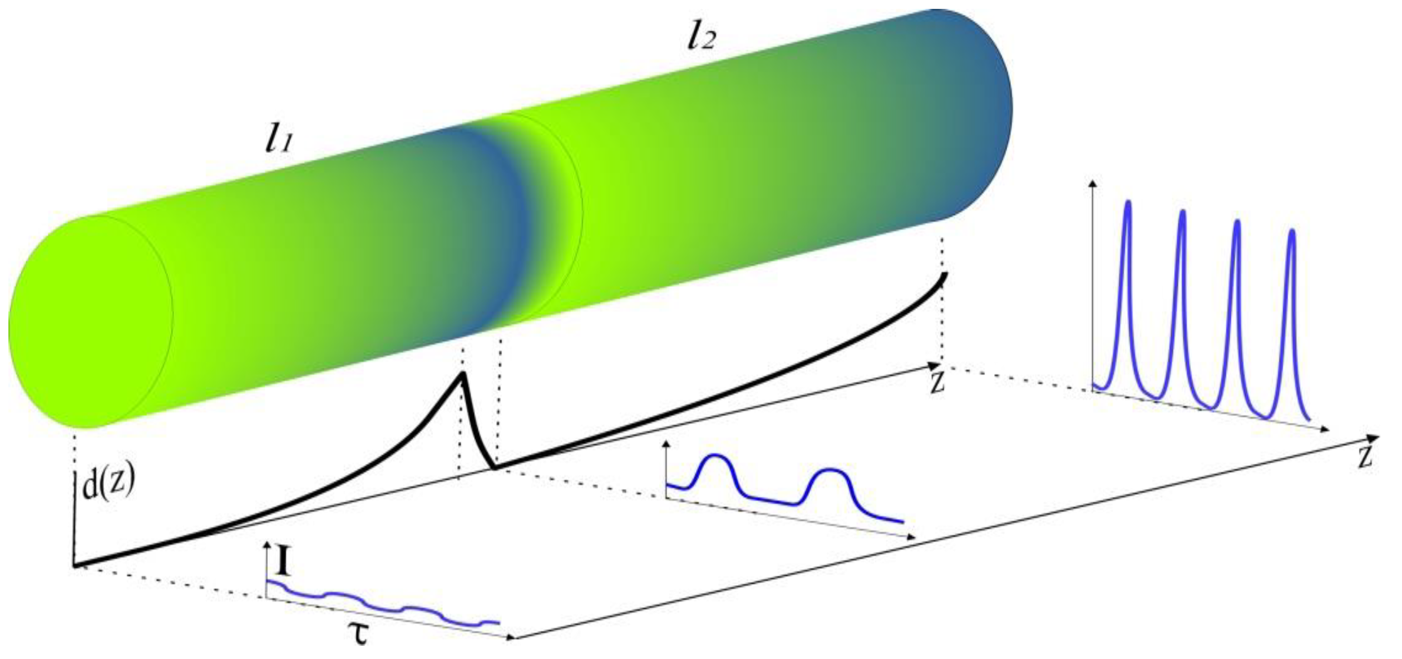
We analyzed numerically that propagation of the input signal through a single fiber segment only does not allow getting pulse trains of a sufficiently high contrast. In order to generate pulse trains from the weakly modulated CW signal, a fiber configuration comprising two active fiber segments with different GVD profiles has to be considered. Such a cascaded fiber configuration is shown in Figure 2. In this configuration, the first fiber segment has the dispersion profile in Equation (17) similar to that shown in Figure 2. Propagating through this fiber, the weakly modulated CW signal increases the modulation depth and acquires a frequency chirp in each signal period. The second fiber segment is much longer than the first one. However, both fiber segments possess the GVD profiles described by Equation (17), but with different parameters. Under the condition that the parameters of the second fiber segment satisfactorily match the signal delivered by the first fiber, it enables effective and smooth conversion of the input signal into a high-power ultrashort pulse train.
Figure 3 shows the evolution of the initial weakly modulated CW signal to the picosecond pulse train in the configuration comprising two fibers with the lengths of l1 = 28 m and l2 = 142 m, as well as the GVD profiles described by Equation (17) with different parameters listed in Table 1.
The distributions of GVD and pulse train peak power along the fiber length are shown in Figure 3a (curves 1 and 2, respectively). Propagating through the first fiber segment, the weakly modulated CW signal is amplified adiabatically. Its shape is changed, the modulation depth increases, and the signal acquires a linear chirp in each signal period. The signal power possesses a linearly increase with the fiber length reaching ~1 W at the first fiber segment output.
The modulated light delivered by the first fiber is introduced into the second fiber. The second fiber provides its conversion into the periodic pulse train. In this process, formation of the contrast pulses occurs due to both adiabatic amplification in the active fiber and nonlinear interaction between the growing pulses and CW background. A stable highly contrast pulse train possessing the peak power of 700 W and a sub THz pulse repetition rate (Figure 3b (curve 3)) is delivered by the cascaded fiber configuration.
It is worth noting that the pulse train repetition rate is strongly defined by the frequency of initial modulation Ω mod , reaching a value as high as ν r 0.5 THz for Ω mod = 3 × 10 12 s 1 . However, it could be slightly tuned by a change of the gain increment in the second fiber (Figure 4). This feature makes the proposed technique useful for many practical applications.

5. Discussion and Conclusions

We proposed an advanced use of nonuniform optical active fibers with a specific dispersion profile both for amplification and generation of ultra-short FM pulse trains. With a single fiber segment, the amplification of a single FM pulse peak power by six orders of magnitude is demonstrated, whereas the cascaded fiber configuration comprising two nonuniform active fibers with different dispersion profiles is shown to enable the generation of the pulse train with a peak power of 700 W and a sub-THz repetition rate from 10 mW weakly modulated CW optical input signal. The repetition rate of the generated pulse trains can be controlled by changing the input signal modulation frequency and, more precisely, through the pump power adjustment in the second fiber segment. Further scaling of the pulse train peak power up to 10 kW, as well as a repetition rates as high as 0.5 THz could be achieved with the fiber configurations comprising three and more similar fiber segments. However, these demonstrations are beyond the scope of this paper.
There is a known scenario for the development of MI in fibers with nonlinear and dispersive parameters that are nonuniform along the length, which was considered in detail in [30,34,35,36,37,38,39,40]. In our case, which differs from the standard scenario for the development of MI [30,34,35,36,37,38,39,40], the generated pulse train is nonperiodic. CW radiation evolves into a train of USPs, which is accompanied by a steady decrease in the USP durations and an increase in their peak power. As a result, FM soliton-like pulses are formed, and their amplitude can exceed by orders of magnitude the peak powers of the so-called Akhmediev breathers, which are formed as a result of the development of MI in homogeneous fibers [40]. The closest scheme to the discussed work was presented in [41,42] for the first time.
A precise control of the pulse repetition rate by adjustment of the input power opens prospects for implementation of the proposed USP generation techniques in radiophotonics [43] and optical metrology, as well as in terahertz clocks demanded for optical computing [14]. Furthermore, the considered systems delivering peak powers over 10 kW are demanded for applications in material processing [1].

Author Contributions

Conceptualization, I.Z. and V.S.; methodology, I.Z.; software, A.A. and V.L.; validation, M.Y. and P.M.; formal analysis, I.Z. and A.A., investigation, V.S. and V.L.; resources, V.S. and A.F.; data curation, A.F. and M.Y.; writing—original draft preparation, V.S. and I.Z.; writing—review and editing, M.Y.; visualization, A.A., V.L. and M.Y.; supervision, I.Z.; project administration, V.S.; funding acquisition, P.M., I.Z., A.F. and V.S. All authors have read and agreed to the published version of the manuscript.

Funding

This research was partially funded by the Ministry of Science and Higher Education of the Russian Federation, grant numbers FNRM-2021-0002, 075-15-2021-581, and by the Russian Science Foundation, grant number 19-72-10037.

Institutional Review Board Statement

Not applicable.

Informed Consent Statement

Not applicable.

Data Availability Statement

Not applicable.

Acknowledgments

P.M. and V.L. are grateful to Russian Foundation for Basic Research (Project No. 19-42-730013). A.A. is supported by sp-4058.2021.5 scholarship.

Conflicts of Interest

The authors declare no conflict of interest.

References

  1. Reid, D.T.; Heyl, C.M.; Thomson, R.R.; Trebino, R.; Steinmeyer, G.; Fielding, H.H.; Holzwarth, R.; Zhang, Z.; Del’Haye, P.; Südmeyer, T.; et al. Roadmap on Ultrafast Optics. J. Opt. 2016, 18, 093006. [Google Scholar] [CrossRef] [Green Version]
  2. Fermann, M.E.; Hartl, I. Ultrafast Fibre Lasers. Nat. Photonics 2013, 7, 868–874. [Google Scholar] [CrossRef]
  3. Akhmanov, S.A.; Vysloukh, V.A.; Chirkin, A.S. Optics of Femtosecond Laser Pulses; American Inst. of Physics: New York, NY, USA, 1992; ISBN 9780883188514. [Google Scholar]
  4. Kryukov, P.G. Ultrashort-Pulse Lasers. Quantum Electron. 2001, 31, 95–119. [Google Scholar] [CrossRef]
  5. Agrawal, G.P. Nonlinear Fiber Optics; Elsevier: Amsterdam, The Netherlands, 2019; ISBN 9780128170427. [Google Scholar]
  6. Geddes, C.G.R.; Toth, C.S.; van Tilborg, J.; Esarey, E.; Schroeder, C.B.; Bruhwiler, D.; Nieter, C.; Cary, J.; Leemans, W.P. High-Quality Electron Beams from a Laser Wakefield Accelerator Using Plasma-Channel Guiding. Nature 2004, 431, 538–541. [Google Scholar] [CrossRef] [PubMed]
  7. Bolshakov, V.V.; Vorob’ev, A.A.; Uryupina, D.S.; Ivanov, K.A.; Morshedian, N.; Volkov, R.V.; Savel’ev, A.B. Hot Electron Generation in a Dense Plasma by Femtosecond Laser Pulses of Subrelativistic Intensity. Quantum Electron. 2009, 39, 669–674. [Google Scholar] [CrossRef]
  8. Lourenco, S.; Kowarsch, N.; Scheid, W.; Wang, P.X. Acceleration of Electrons and Electromagnetic Fields of Highly Intense Laser Pulses. Laser Part. Beams 2010, 28, 195–201. [Google Scholar] [CrossRef]
  9. Bonse, J.; Hohm, S.; Kirner, S.V.; Rosenfeld, A.; Kruger, J. Laser-Induced Periodic Surface Structures-A Scientific Evergreen. IEEE J. Sel. Top. Quantum Electron. 2017, 23, 109–123. [Google Scholar] [CrossRef]
  10. Buck, A.; Wenz, J.; Xu, J.; Khrennikov, K.; Schmid, K.; Heigoldt, M.; Mikhailova, J.M.; Geissler, M.; Shen, B.; Krausz, F.; et al. Shock-Front Injector for High-Quality Laser-Plasma Acceleration. Phys. Rev. Lett. 2013, 110, 185006. [Google Scholar] [CrossRef]
  11. Kalaycioglu, H.; Elahi, P.; Akcaalan, O.; Ilday, F.O. High-Repetition-Rate Ultrafast Fiber Lasers for Material Processing. IEEE J. Sel. Top. Quantum Electron. 2018, 24, 1–12. [Google Scholar] [CrossRef]
  12. Kippenberg, T.J.; Holzwarth, R.; Diddams, S.A. Microresonator-Based Optical Frequency Combs. Science 2011, 332, 555–559. [Google Scholar] [CrossRef]
  13. Li, X.; Zou, W.; Chen, J. Passive Harmonic Hybrid Mode-Locked Fiber Laser with Extremely Broad Spectrum. Opt. Express 2015, 23, 21424. [Google Scholar] [CrossRef] [PubMed]
  14. Maddaloni, P.; Cancio, P.; de Natale, P. Optical Comb Generators for Laser Frequency Measurement. Meas. Sci. Technol. 2009, 20, 052001. [Google Scholar] [CrossRef]
  15. Boscolo, S.; Finot, C. (Eds.) Shaping Light in Nonlinear Optical Fiber; Wiley: New York, NY, USA, 2017; pp. 1–505. ISBN 9781119088127. [Google Scholar]
  16. Korobko, D.A.; Okhotnikov, O.G.; Zolotovskii, I.O. High-Repetition-Rate Pulse Generation and Compression in Dispersion Decreasing Fibers. J. Opt. Soc. Am. B 2013, 30, 2377–2386. [Google Scholar] [CrossRef]
  17. Korobko, D.A.; Okhotnikov, O.G.; Stoliarov, D.A.; Sysolyatin, A.A.; Zolotovskii, I.O. Broadband Infrared Continuum Generation in Dispersion Shifted Tapered Fiber. J. Opt. Soc. Am. B 2015, 32, 692–700. [Google Scholar] [CrossRef]
  18. Korobko, D.A.; Okhotnikov, O.G.; Stoliarov, D.A.; Sysoliatin, A.A.; Zolotovskii, I.O. Highly Nonlinear Dispersion Increasing Fiber for Femtosecond Pulse Generation. J. Lightwave Technol. 2015, 33, 3643–3648. [Google Scholar] [CrossRef]
  19. Rehan, M.; Kumar, G.; Rastogi, V.; Korobko, D.A.; Sysolyatin, A.A. Compression of Femtosecond Pulses in a Wide Wavelength Range Using a Large-Mode-Area Tapered Fiber. Laser Phys. 2019, 29, 025104. [Google Scholar] [CrossRef] [Green Version]
  20. Sysoliatin, A.A.; Nolan, D.A. Optical Signal Processing in Dispersion Varying Fiber. J. Nonlinear Opt. Phys. Mater. 2007, 16, 171–184. [Google Scholar] [CrossRef]
  21. Korobko, D.A.; Okhotnikov, O.G.; Zolotovskii, I.O. Multistage Fiber Preamplifier Employing Spectral Compression for Generation of High-Energy Laser Pulses. J. Opt. Soc. Am. B 2016, 33, 239–245. [Google Scholar] [CrossRef]
  22. Korobko, D.A.; Okhotnikov, O.G.; Sysolyatin, A.A.; Yavtushenko, M.S.; Zolotovskii, I.O. Optical Amplifier with Tailored Dispersion for Energy Scaling of Similaritons. J. Opt. Soc. Am. B 2013, 30, 582–588. [Google Scholar] [CrossRef]
  23. Zolotovsky, I.O.; Yavtushenko, M.S.; Sysoliatin, A.A.; Sementsov, D.I.; Yavtushenko, I.O.; Okhotnikov, O.G. Parabolic Pulse Generation in the Nonlinear Nonuniform Fibre Cascade. In Proceedings of the Nonlinear Frequency Generation and Conversion: Materials, Devices, and Applications X, San Francisco, CA, USA, 24–27 January 2011; Volume 7917. [Google Scholar]
  24. Yavtushenko, M.S.; Zolotovskii, I.O.; Okhotnikov, O.G.; Sysoliatin, A.A. Chirped Pulse Shaping via Fiber Dispersion Modulation. In Proceedings of the Fiber Lasers VII: Technology, Systems, and Applications, San Francisco, CA, USA, 25–28 January 2010; Volume 7580. [Google Scholar]
  25. Korobko, D.A.; Sysoliatin, A.A.; Yavtushenko, M.S.; Zolotovskii, I.O. A Multistage Fiber Amplifier with a Decreased Rate of Frequency Modulation of Amplified Pulses. Laser Phys. 2013, 23, 095111. [Google Scholar] [CrossRef]
  26. Sarma, A.K. Modulation Instability in Nonlinear Complex Parity-Time Symmetric Periodic Structures. J. Opt. Soc. Am. B 2014, 31, 1861. [Google Scholar] [CrossRef] [Green Version]
  27. Krolikowski, W.; Bang, O.; Rasmussen, J.J.; Wyller, J. Modulational Instability in Nonlocal Nonlinear Kerr Media. Phys. Rev. E 2001, 64, 016612. [Google Scholar] [CrossRef] [PubMed] [Green Version]
  28. Królikowski, W.; Bang, O.; Nikolov, N.I.; Neshev, D.; Wyller, J.; Rasmussen, J.J.; Edmundson, D. Modulational Instability, Solitons and Beam Propagation in Spatially Nonlocal Nonlinear Media. J. Opt. B Quantum Semiclassical Opt. 2004, 6, S288–S294. [Google Scholar] [CrossRef] [Green Version]
  29. Schukarev, I.; Korobko, D.A.; Zolotovskii, I. Parabolic Pulse Generation in Short Fiber Amplifiers. J. Opt. 2019, 21, 105505. [Google Scholar] [CrossRef]
  30. Agrawal, P. Modulation Instability in Erbium-Doped Fiber Amplifiers. IEEE Photonics Technol. Lett. 1992, 4, 562–564. [Google Scholar] [CrossRef]
  31. Chernikov, S.V.; Mamyshev, P.V. Femtosecond Soliton Propagation in Fibers with Slowly Decreasing Dispersion. J. Opt. Soc. Am. B 1991, 8, 1633. [Google Scholar] [CrossRef]
  32. Akhmetshin, U.G.; Bogatyrev, V.A.; Senatorov, A.K.; Sysolyatin, A.A.; Shalygin, M.G. New Single-Mode Fibres with the Flat Spectral Dependence of the Chromatic Dispersion Varying over the Fibre Length. Quantum Electron. 2003, 33, 265–267. [Google Scholar] [CrossRef]
  33. Borisova, C.; Zolotovskii, I.; Korobko, D.; Sementsov, D.; Sysoliatin, A.; Yavtushenko, M. Cascade Scheme of FM Pulse Amplification in Length-Inhomogeneous Active Waveguides with Normal Dispersion. In Proceedings of the Fiber Lasers X: Technology, Systems, and Applications, San Francisco, CA, USA, 4–7 February 2013; Volume 8601. [Google Scholar]
  34. Xu, W.; Zhang, S.; Chen, W.; Luo, A.; Liu, S. Modulation Instability of Femtosecond Pulses in Dispersion-Decreasing Fibers. Opt. Commun. 2001, 199, 355–360. [Google Scholar] [CrossRef]
  35. Tai, K.; Tomita, A.; Jewell, J.L.; Hasegawa, A. Generation of Subpicosecond Solitonlike Optical Pulses at 0.3 THz Repetition Rate by Induced Modulational Instability. Appl. Phys. Lett. 1986, 49, 236–238. [Google Scholar] [CrossRef]
  36. Spence, D.E.; Wielandy, S.; Tang, C.L.; Bosshard, C.; Günter, P. High Average Power, High-repetition Rate Femtosecond Pulse Generation in the 1–5 Μm Region Using an Optical Parametric Oscillator. Appl. Phys. Lett. 1996, 68, 452–454. [Google Scholar] [CrossRef]
  37. Kobayashi, T.; Sueta, T.; Cho, Y.; Matsuo, Y. High-repetition-rate Optical Pulse Generator Using a Fabry-Perot Electro-optic Modulator. Appl. Phys. Lett. 1972, 21, 341–343. [Google Scholar] [CrossRef]
  38. Conforti, M.; Mussot, A.; Kudlinski, A.; Trillo, S. Modulational Instability in Dispersion Oscillating Fiber Ring Cavities. Opt. Lett. 2014, 39, 4200. [Google Scholar] [CrossRef] [PubMed] [Green Version]
  39. Demircan, A.; Bandelow, U. Supercontinuum Generation by the Modulation Instability. Opt. Commun. 2005, 244, 181–185. [Google Scholar] [CrossRef]
  40. Dudley, J.M.; Genty, G.; Dias, F.; Kibler, B.; Akhmediev, N. Modulation Instability, Akhmediev Breathers and Continuous Wave Supercontinuum Generation. Opt. Express 2009, 17, 21497. [Google Scholar] [CrossRef]
  41. Mamyshev, P.V.; Chernikov, S.V.; Dianov, E.M.; Prokhorov, A.M. Generation of a High-Repetition-Rate Train of Practically Noninteracting Solitons by Using the Induced Modulational Instability and Raman Self-Scattering Effects. Opt. Lett. 1990, 15, 1365. [Google Scholar] [CrossRef]
  42. Chernikov, S.V.; Taylor, J.R.; Mamyshev, P.V.; Dianov, E.M. Generation of Soliton Pulse Train in Optical Fibre Using Two CW Singlemode Diode Lasers. Electron. Lett. 1992, 28, 931–932. [Google Scholar] [CrossRef]
  43. Degli-Eredi, I.; An, P.; Drasbæk, J.; Mohammadhosseini, H.; Nielsen, L.; Tønning, P.; Rommel, S.; Monroy, I.T.; Heck, M.J.R. Millimeter-Wave Generation Using Hybrid Silicon Photonics. J. Opt. 2021, 23, 043001. [Google Scholar] [CrossRef]
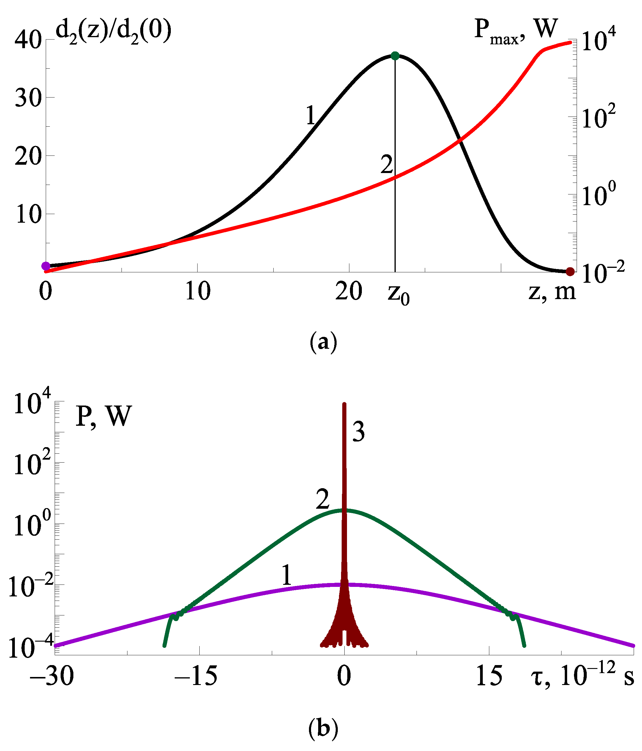
Figure 1. Evolution of the secant–hyperbolic FM-pulse envelope in the fiber segment: (a) dispersion profile (curve 1, left axis), pulse peak power (curve 2, right axis); (b) pulse envelope at the fiber segment input (curve 1), at the point z = z0 (curve 2), and at the fiber segment output (curve 3). The violet, dark-green, and brown points on curve 1 in (a) correspond to the curves of the same-colors at (b). The parameters of fiber and input signal are listed in Table 1.
Photonics 09 00160 g001
Figure 2. Schematic of USP generation in the fiber configuration comprising two nonuniform active fiber segments and conversion of the input CW signal into USP. The black curve shows the GVD profile. Optical signals propagating through the configuration are shown by blue curves.
Photonics 09 00160 g002
Figure 3. Evolution of the input optical signal in Equation (22) to the picosecond pulse train in the fiber cascade comprising two fibers with the GVD profile in Equation (17). (a) The GVD distribution along the fiber length (curve 1); the pulse peak power as a function of the fiber length (curve 2); (b) the optical signals at the first fiber segment input (curve 1), at the second fiber segment input (curve 2), and at the second fiber segment output (curve 3). The violet, blue and brown points on the curve 1 at (a) correspond to curves of the same colors in (b).
Photonics 09 00160 g003
Figure 4. Pulse repetition rate ν r as a function of the gain increment in the second fiber g 2 at different modulation frequencies Ω mod = ( 1 ; 2 ; 3 ) × 10 12 s 1 (curves 1–3, respectively).
Photonics 09 00160 g004
Table 1. Parameters used for calculations.
SignDescriptionValueFigures
P 0 Peak power of input signal0.01 W1,3,4
τ 0 Input pulse duration10 ps1
α 0 Initial frequency modulation (chirp) of pulse1024 s−21
m Modulation depth0.013,4
Ω mod Modulation frequency2 × 1012 s−13,4
d 20 Sec ond - order   dispersion   at   z = 0 –10−27 s2/m 1,3,4
d 3 Third-order dispersion−10−40 s3/m3,4
R 0 Kerr nonlinearity coefficient10−3 (W·m)−11,3,4
T R Raman response time of medium 5 × 10⁻¹⁵ s1,3,4
g 0 Optical fiber material gain increment0.1 m−11
g 1 Optical fiber first section material gain increment0.1 m−13,4
g 2 Optical fiber second section material gain increment0.015 m−13,4
Publisher’s Note: MDPI stays neutral with regard to jurisdictional claims in published maps and institutional affiliations.