1. Introduction
The emerging location-based services (LBSs) have raised increasing interest in localization technologies [
1]. Satellite-based global positioning systems are widely used in outdoor environments. However, satellite signals suffer from fading when passing though solid walls, thus their positioning accuracy will be severely influenced in indoor environments such as underground parking, tunnels, and office buildings surrounded by skyscrapers. With the development of visible light communication (VLC) technologies, the visible light positioning (VLP) system using light-emitting diodes (LEDs) has been considered as a potential candidate for the next-generation indoor positioning system, due to its advantages of high accuracy, high efficiency, and low cost [
2,
3]. By modulating signals to existing lighting facilities, VLP systems can offer various indoor LBSs such as high-accurate indoor navigation, asset tracking, and autonomous robot control.
The simplest indoor VLP scheme is based on the principle of proximity and its positioning accuracy is usually in meters [
4]. To improve the positioning accuracy, different VLP schemes based on trilateration or triangulation were reported, which can achieve centimeter-level VLP [
5,
6,
7]. However, to offer positioning information for trilateration or triangulation, conventional VLP systems usually require at least three LEDs as transmitters to convey VLP signals according to the time domain multiplexing (TDM) or frequency domain multiplexing (FDM) protocols to avoid mutual interference at the receiver and make it easy for the receiver to distinguish between VLP signals [
8,
9]. Thus, at least three time slots or frequency bands are allocated for VLP. Since the bandwidth of off-the-shelf LEDs is narrow and usually a few of tens of MHz [
10], VLP will inevitably limit the available bandwidth of VLC in an integrated VLC and VLP system [
11]. To ensure the ample capacity of VLC, new approaches are required to reduce the time or frequency resources allocated for VLP. This study will focus on the VLP mechanism to propose a new VLP model and its corresponding strategies to support VLP with fewer bandwidth resources.
Another issue is that the LED condition of a VLP system could be constrained in some common scenarios, e.g.,: (i) when the LED number is insufficient, i.e., less than three; and (ii) when LED lamps are installed along a straight line, e.g., in a corridor or a tunnel. In these scenarios, the receiver is likely to detect the VLP signals from only one or two LEDs. Thus, conventional VLP schemes based on trilateration or triangulation cannot be directly applied. Different approaches have been proposed to perform indoor VLP with less than three LEDs, which can be categorized as two-dimensional (2D) [
12,
13,
14] or three-dimensional (3D) [
15,
16,
17] schemes. However, all these schemes require additional equipment such as a camera [
12,
13,
15], a mirror [
14], line lasers [
16], or at least three PDs [
17], which could increase the system complexity and needs to be simplified. Motivated by this, this work will particularly focus on the 3D VLP scheme, which requires fewer PDs when the LED condition is constrained.
Recently, receiver orientation estimation has become an additional function of VLP. Joint VLP and orientation estimation schemes were proposed in [
18,
19], and they both support only 2D VLP with quite a number of LEDs (e.g., twenty LEDs in [
18], and forty-eight LEDs in [
19]). However, there have been no related works specifically dedicated to VLP schemes that can support simultaneous 3D localization and receiver orienteering using less than three LEDs and a PD-based receiver. Therefore, this work will also try to fill in the gap.
In this paper, we propose a novel indoor 3D VLP and orienteering (VLPO) scheme using two LEDs and a pair of PDs. To the best of our knowledge, this is the first time that a two-LED-two-PD-based indoor 3D VLPO scheme is proposed, by which only two time slots or frequency bands are required to convey VLP signals. Thus, the bandwidth resources allocated for VLP can be effectively reduced as compared with conventional schemes based on trilateration or triangulation. In addition, the proposed scheme can achieve a good trade-off between the system complexity and the localization capability. As shown in
Table 1, by using two LEDs and two PDs without any other types of equipment, our scheme is the only one that supports simultaneous 3D VLP and orientation estimation for a tilted receiver, thus it can be considered as a promising solution, especially when the LED condition is constrained.
The concept of the VLPO scheme was shown in our conference paper [
20], wherein we have preliminarily verified its feasibility assuming the receiver to face upwards. However, when the receiver tilts, the model in [
20] cannot be directly applied and needs to be modified. Therefore, in this work, we further develop the VLPO scheme by considering the scenario of a tilted receiver. To eliminate the potential location uncertainty caused by the receiver tilt, we propose a new location selection strategy for the VLPO system to determine the true location of the receiver. We conduct extensive simulations to evaluate the positioning accuracy and orienteering accuracy in a 3 m × 5 m × 3 m indoor space. The influence from the interval between PDs, the ranging error between LEDs and PDs, and the polar angle of the tiled receiver is also evaluated. Results show that the proposed scheme is efficient to achieve accurate 3D VLPO when the LED condition is constrained. Specifically, when the receiver faces upwards, the proposed scheme can achieve a mean 3D positioning error of 7.4 cm and a mean azimuthal error of 7.0°. Moreover, when the receiver tilts with a polar angle of 10°, the proposed scheme can still achieve accurate VLP and orienteering, with 90.3% of 3D positioning errors less than 20 cm and 92.6% of azimuthal errors less than 5°. Results also indicate that increasing the interval between PDs and reducing the ranging error between LEDs and PDs help enhance the accuracy of VLPO, and the receiver tilt only slightly degrades the performance of the VLPO scheme.
The rest of this paper is organized as follows.
Section 2 presents the principle of the proposed 3D VLPO system in detail. Simulations and performance analyses are conducted in
Section 3. Finally, we conclude the paper in
Section 4.
2. Proposed VLPO Scheme
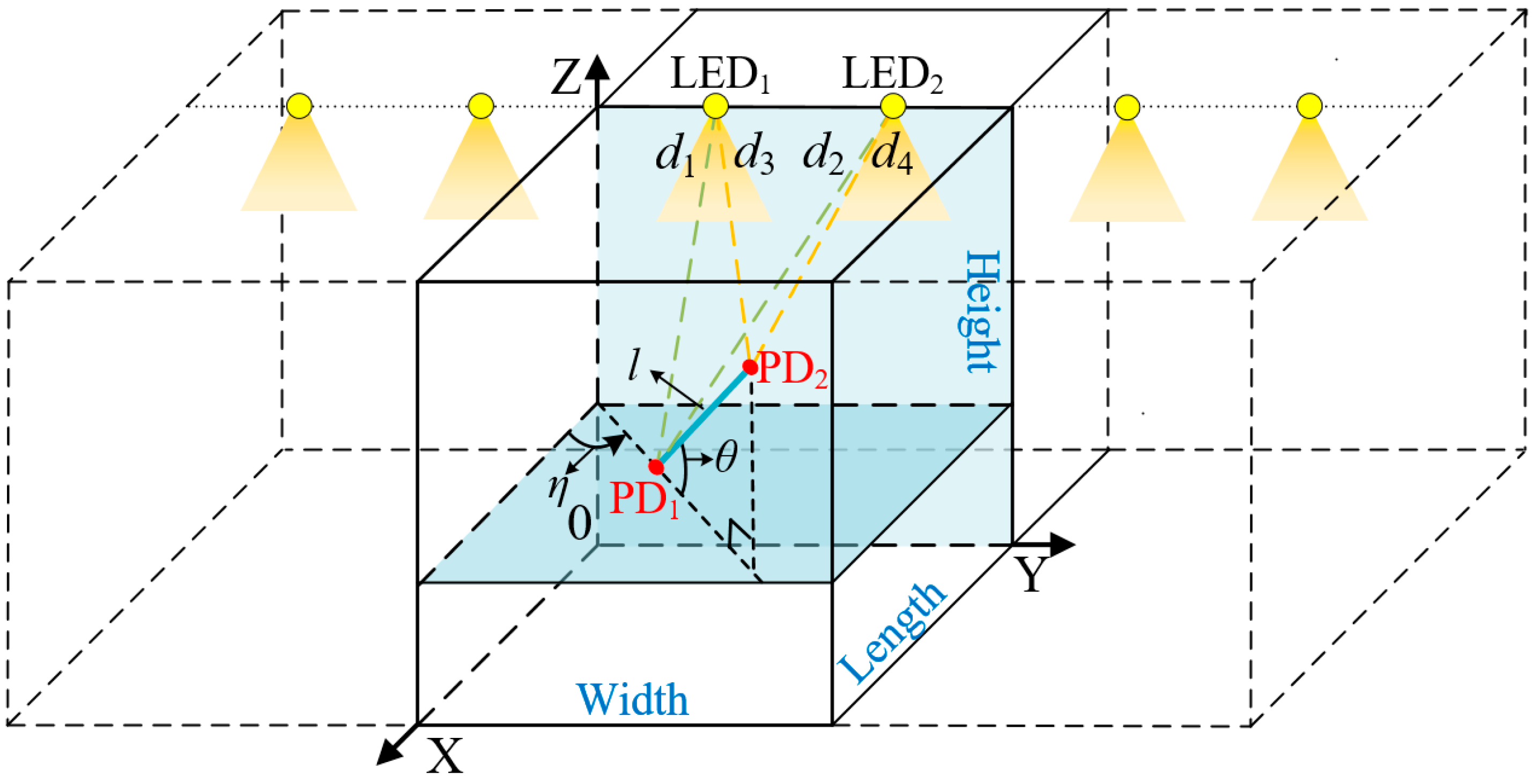
In this study, we assume a multi-cell VLPO system, in which there are multiple LEDs installed along a straight line in the ceiling, and mobile receivers are distributed at different indoor locations. The LEDs are divided into different groups in pairs to spatially form multiple VLPO cells. Based on this multi-cell configuration, we focus on VLPO within a single cell where a mobile receiver can only detect the VLP signals emitted from two LEDs (LED
1 and LED
2). Without loss of generality, we abstract the receiver into a line segment and assume that a pair of photo-detectors (PD
1 and PD
2) are mounted on both ends of the receiver.
Figure 1 shows the architecture of the proposed VLPO system. The 3D coordinates of LED
1 and LED
2 are (
xt1,
yt1,
zt1) and (
xt2,
yt2,
zt2), respectively, which are a priori knowledge at the receiver. The 3D coordinates of PD
1 and PD
2 are (
xr1,
yr1,
zr1) and (
xr2,
yr2,
zr2), respectively, which are unknown at the receiver and need to be estimated. We use the midpoint of PD
1 and PD
2 to represent the location of the receiver, i.e., (
xR,
yR,
zR) = ((
+
)/2, (
+
)/2, (
+
)/2). We also define the direction pointing from PD
1 towards PD
2 as the orientation of the receiver. Thus, the azimuthal angle of the receiver is defined by the angular rotation
η (−180° <
η ≤ 180°) from the positive X-axis to the projection of the receiver (from PD
1 to PD
2) on the XY-plane. Therefore, if we successfully estimate the 3D coordinates of PD
1 and PD
2, then the location and the orientation of the receiver can be calculated.
To estimate the coordinates of PD
1 and PD
2, we assume that the LEDs and PDs are perfectly synchronized to a common clock, and the VLP signals launched by the LEDs are used as the basis of ranging. Based on the ranging methods of time-of-arrival (TOA) or phase-difference-of-arrival (PDOA) [
21,
22], the distances between the two LEDs and two PDs can be measured, and their estimation accuracy is typically in the order of centimeters [
21]. We define the real distance between LED
1 and PD
1, LED
2 and PD
1, LED
1 and PD
2, LED
2 and PD
2 to be
d1,
d2,
d3, and
d4, respectively. Therefore, we obtain the following geometrical relationships:
where
(
i = 1, 2, 3, 4) is the estimated values of
di (
i = 1, 2, 3, 4) obtained by ranging,
is the coordinate of PD
1 to be estimated, and
is the coordinate of PD
2 to be estimated. To offer richer information for performing VLPO, the interval between PD
1 and PD
2 is known at the receiver and fixed at
l. Additionally, we assume that the polar angle
θ (0° ≤
θ ≤ 90°) of the tilted receiver can be acquired by extra sensors at the receiver [
22]. When
θ = 0°, the receiver faces upwards. Based on these presumptions, we can derive additional geometrical relationships:
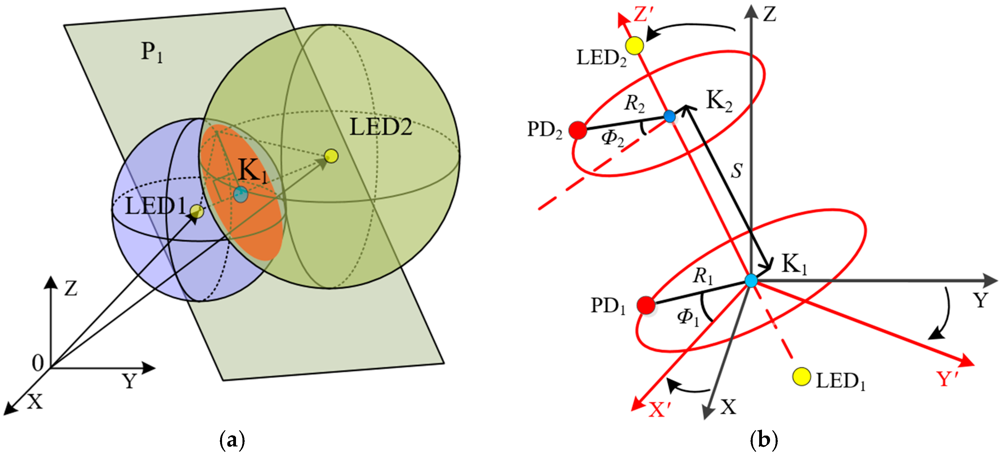
According to the above nonlinear system of equations from Equations (1)–(6), we expect to solve the coordinates of PD1 and PD2. However, it would be difficult to directly solve the coordinates of PDs from Equations (1)–(6) in the current XYZ-coordinate system. Thus, we divide the solving process into three steps, which includes establishing intersection circles, conducting coordinate transformations, and excluding redundant solutions.
Figure 2a shows the schematic diagram of establishing intersection circles. In this step, we first subtract between Equations (1) and (2), i.e., the two spherical surfaces centered at LED
1 and LED
2, to obtain a plane equation, which is described by a plane P
1. PD
1 is located in the plane P
1, specifically, on the intersection circle K
1 between the spherical surfaces Equations (1) and (2). Here, K
1 is centered at (
a1,
b1,
c1) with a radius of
R1. Similarly, after subtracting between Equations (3) and (4), PD
2 is located in a plane P
2, specifically, on the intersection circle K
2 centered at (
a2,
b2,
c2) with a radius of
R2. For the intersection circles K
1 and K
2, the coordinates of K
i (
i = 1, 2) are given by:
where
L is the distance between LED
1 and LED
2, and
wi (
i = 1, 2) is the distance from LED
1 to the Plane P
i (
i = 1, 2), derived as:
Additionally, the radiuses
Ri (
i = 1, 2) of the intersection circles can be written by:
Now, based on the circles K
1 and K
2, the solving process for the coordinates of PDs can be simplified by constructing new coordinate systems. Thus, in the second step, we conduct coordinate transformations, as shown in
Figure 2b. We first transform the XYZ-coordinate system into the X
′ Y
′ Z
′-coordinate system, in which K
1 is the origin point, line K
1K
2 forms the Z
′-axis, and the intersection line between the plane P
1 and the XY-plane forms the X
′-axis. Next, we transform the X
′ Y
′ Z
′-coordinate system into the cylindrical coordinate system, in which the cylindrical coordinates of PD
1 and PD
2 are denoted by (
R1,
Φ1, 0) and (
R2,
Φ2,
S), respectively. Here,
S is the distance between K
1 and K
2. After coordinate transformations, Equations (5) and (6) can be written in the form of the cylindrical coordinates:
where
M = (
R12 +
R22 +
S2 −
l2)/(2
R1R2),
β =
,
γ =
c/
S,
a =
a2 −
a1,
b =
b2 −
b1,
c =
c2 −
c1, and
S =
. By solving (12) and (13),
Φ1 and
Φ2 can be obtained. Then, we perform coordinate inverse transformations to recover the coordinates of PD
1 and PD
2 in the XYZ-coordinate system, which are, respectively, given by:
Here, the orthonormal bases are given by
,
, and
.
Based on the solving process from Equations (12)–(15), we get a total of four solutions. In other words, due to geometrical symmetry, a total of four pairs of the estimated coordinates of PD
1 and PD
2 are distributed in the space, among which only one is true. This means that the location of the receiver cannot be determined due to multiple solutions, and we call this situation as location uncertainty. To eliminate location uncertainty, the third step is to exclude the redundant solutions and get the true solution. In practice, the height of the VLP receiver is lower than the height of LED transmitters. Thus, we first exclude the solutions that are above the ceiling by setting the first constraint condition:
. Among the rest of solutions, we perform a further exclusion by considering the possible moving range of the receiver. In this study, we assume that the receiver moves within the constrained space on the outside of the YZ-plane by setting the second constraint condition:
, which is shown in
Figure 1.
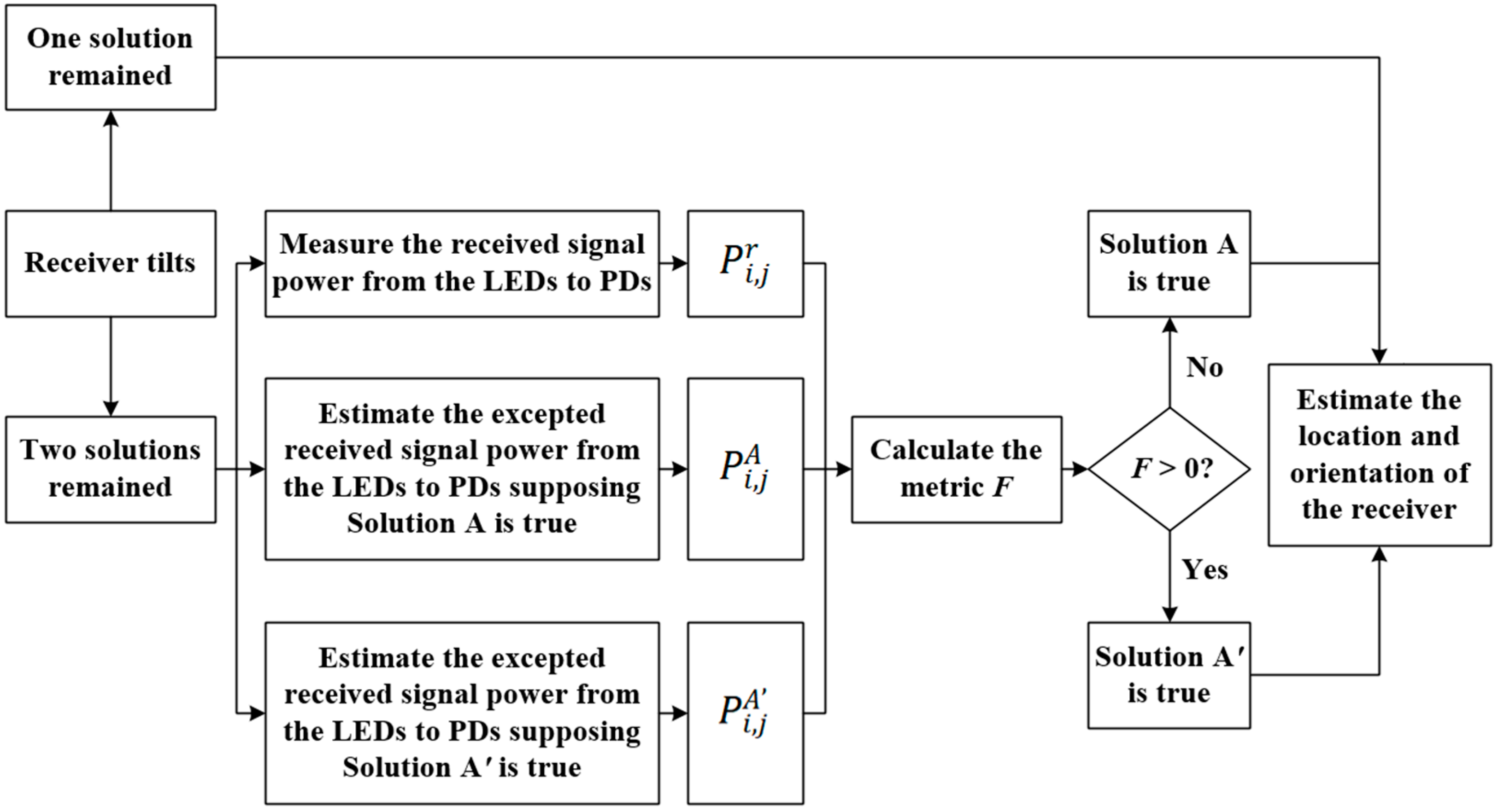
During our study, we find that if the receiver faces upwards, i.e., the polar angle θ = 0°, then only one solution remains after considering the above two constraint conditions. This solution is taken as the estimated coordinates of PD1 and PD2, based on which the 3D location and the orientation of the receiver can be finally calculated. However, if the receiver tilts, i.e., θ ≠ 0°, we may obtain one or two solutions remained after considering the above two constraint conditions, depending on the location of the receiver, the orientation of the receiver, and the ranging error between LEDs and PDs. Therefore, to eliminate the location uncertainty caused by the receiver tilt, we propose a location selection strategy to select the true location of PDs.
Figure 3 shows a flow chart of the location selection strategy. For a tilted receiver, if there remains only one pair of the estimated coordinates of PD
1 and PD
2, i.e., the case of one solution, then they can be directly used to perform VLPO for the receiver. However, if there remain two solutions, then we need to exclude the redundant solution by making comparisons between the received signal power at the PDs and the expected received signal power at the specific locations. Without loss of generality, we use the Solution A and the Solution A
′ to represent the two possible solutions remained, among which only one is true. For the Solution A, the estimated coordinates of PD
1 and PD
2 are, respectively, defined by (
,
,
) and (
,
,
), and for the Solution A
′, the estimated coordinates of PD
1 and PD
2 are, respectively, defined by (
,
,
) and (
,
,
).
We first measure the received signal power from LED
i (
i = 1, 2) to PD
j (
j = 1, 2), which is expressed by:
where
s(
t) is the transmitted VLP signal,
T is the duration of
s(
t), and
is the total channel impulse response (CIR) from LED
i (
i = 1, 2) to PD
j (
j = 1, 2), which can be further written by [
23,
24]:
Here, is Dirac function. From LEDi (i = 1, 2) to PDj (j = 1, 2), is the line-of-sight (LOS) CIR, is the non-LOS (NLOS) CIR, and represent the signal time delays of the LOS and NLOS channels, respectively, is the DC gain of the LOS channel, and is the gain of the NLOS channel with a time delay .
We assume all the LEDs have a Lambertian radiation pattern. Then, by supposing that the Solution A is true, we can estimate the expected received signal power from LED
i (
i = 1, 2) to PD
j (
j = 1, 2) based on the coordinates in Solution A, which is derived by [
7,
23]:
where
is the transmitted power of LED
i (
i = 1, 2),
m is the Lambertian emission order of LEDs,
Ar is the effective area of PDs,
Ts is the gain of an optical filter,
g is the gain of an optical concentrator. Similarly, by supposing that the Solution A
′ is true, we can also estimate the expected received signal power from LED
i (
i = 1, 2) to PD
j (
j = 1, 2) based on the coordinates in Solution A
′, which is derived by [
7,
23]:
Next, by comparing the power differences between
,
, and
, we construct a metric
F to determine the true solution, which is written as:
If
F > 0, then the Solution A
′ is selected as the true solution for the subsequent location and orientation estimation of the receiver; otherwise, the Solution A is selected.
Finally, by using the single solution remained, the 3D coordinate of the receiver is estimated by
, and its azimuthal angle
η is estimated by:
where sign (·) represents sign function.
3. Simulation Results and Discussions
We evaluate the performance of the proposed VLPO scheme in a 3 m × 5 m × 3 m (length × width × height) indoor space based on the XYZ-coordinate system, as shown in
Figure 1. In a considered VLPO cell, there are only two LED transmitters (LED
1 and LED
2) and a mobile receiver. LED
1 and LED
2 are located at (0, 1.5, 3) and (0, 3.5, 3), respectively, both of which have a Lambertian radiation pattern. Two PDs (PD
1 and PD
2) are mounted at both ends of the receiver to jointly estimate the location and the orientation of the receiver. Around the VLPO cell, there stands three walls, which are represented by three plane equations: (i)
x = 3, 0 ≤
y ≤ 5, 0 ≤
z ≤ 3; (ii)
y = 0, 0 ≤
x ≤ 3, 0 ≤
z ≤ 3; and (iii)
y = 5, 0 ≤
x ≤ 3, 0 ≤
z ≤ 3. Thus, the channel between the LEDs and PDs consists of both LOS and NLOS channels, wherein the first indoor reflection is considered. We assume that the TOA ranging method is used to estimate the distances between the LEDs and PDs. However, due to many factors including the geometry of the room, the frequency and transmitted power of the VLP signal, and the physical characteristics of LEDs and PDs, the distance estimation accuracy of the TOA method will be influenced [
21]. Therefore, random estimation errors occur with respect to the real distances
d1,
d2,
d3, and
d4 between LEDs and PDs. We assume these ranging errors are zero-mean, independent and identically Gaussian distributed, and they have the same standard deviation denoted as Δ
d. In our simulations, we assume that the receiver is located at certain test locations and the interval between adjacent test locations at the same height is 0.5 m. The receiver faces upwards (
θ = 0°) in
Figure 4,
Figure 5,
Figure 6 and
Figure 7, and can be tilted (
θ > 0°) in
Figure 8,
Figure 9,
Figure 10 and
Figure 11. The azimuthal angle of the receiver is randomly distributed in the range of −180° <
η ≤ 180°. To calculate the cumulative distribution functions (CDFs) of the positioning error and the azimuthal error, we conduct Monte Carlo simulations at least 50 times at each test location.
Table 2 lists the key parameters of the indoor VLPO system. Other parameters of the receiver are the same as those in [
23].
We first evaluate the performance of the VLPO scheme when the receiver faces upwards (
θ = 0°).
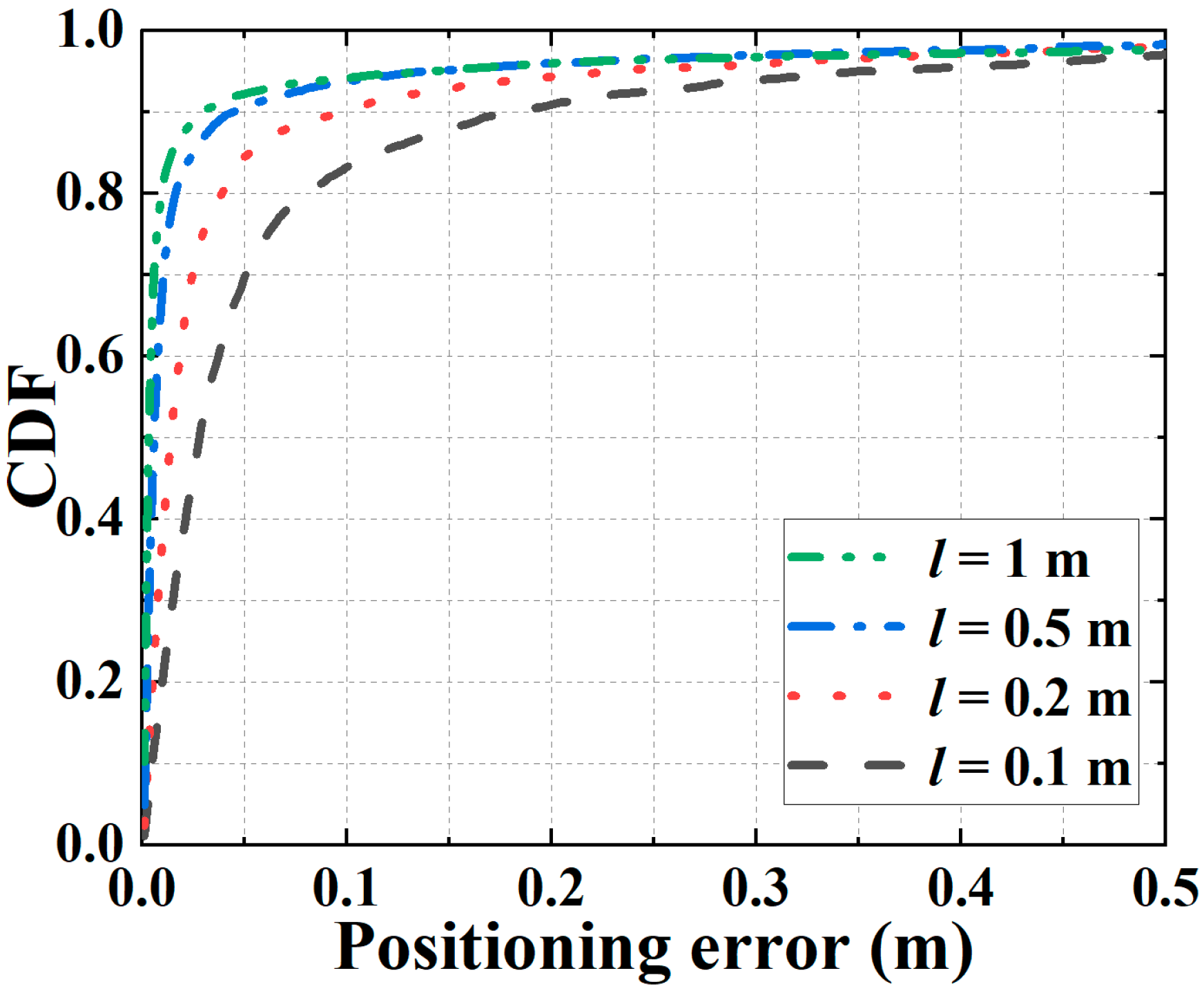
Figure 4 shows the simulated CDFs of the 3D positioning errors when the receiver is fixed at a specific location (0.5, 1, 1). Different curves represent the CDFs obtained by adopting different intervals
l between PDs. We assume the standard deviation Δ
d of the ranging error is 0.025 m. We note that, when
l is 0.1 m, 0.2 m, 0.5 m, and 1 m, the probability of achieving 3D positioning errors less than 10 cm is 83.2%, 90.2%, 93.7%, and 94.1%, respectively. This is because when Δ
d is fixed, adopting a larger
l helps enhance the tolerance against the ranging error, thereby improving the positioning accuracy. Specifically, around 90% of 3D positioning errors are less than 9.8 cm when
l is 0.2 m, and by further increasing
l to 0.5 m, 90% of 3D positioning errors are less than 4.5 cm, thus verifying the high positioning accuracy of the proposed VLPO scheme when
θ = 0°.
To evaluate the performance of the VLPO scheme at different locations,
Figure 5 shows an example of 3D positioning results in different receiving planes at the height of 0.5 m, 1 m, and 1.5 m. Here, we assume that the interval between PDs is 0.2 m and the standard deviation of the ranging error is 0.025 m. We test 77 locations in each receiving plane, thus a total of 231 locations are tested for performance evaluation in the considered indoor space. We use “+” to represent the real locations of the receiver and “○” to represent the coordinates estimated from the proposed VLPO scheme. On the left of
Figure 5, it can be observed that most of the estimated 3D locations are close to their corresponding real locations, thus verifying the effectiveness of the proposed VLPO scheme at different locations. By comparison, we find that the 3D positioning accuracy is related to the height of the receiver. For example, at the height of 0.5 m, 1 m, and 1.5 m, the mean 3D positioning error is 5.9 cm, 8.3 cm, and 14.2 cm, respectively. Thus, when the receiver is at a lower location, it tends to get a more accurate 3D positioning result. The reason is that lower PDs have larger distances to LEDs, thus enhancing their tolerance against the ranging error. On the right of
Figure 5, we show the bird-eye view of the 3D positioning results, i.e., 2D positioning results, for the test locations at the height of 1 m, wherein the mean positioning error is 6.9 cm, which can meet the needs of most location-based services.
By considering the test locations in the receiving plane at the height of 1 m in
Figure 5,
Figure 6a shows the simulated CDFs of the 3D positioning errors at different locations. We assume Δ
d = 0.025 m and compare the CDFs obtained by adopting different intervals
l between PDs. As can be seen, due to the same reason as in
Figure 4, increasing
l can effectively improve the overall positioning accuracy in the considered receiving plane. Specifically, when
l is 0.1 m, 0.2 m, 0.5 m, and 1 m, around 90% of 3D positioning errors are less than 44.9 cm, 28.4 cm, 13.2 cm, and 7.9 cm, respectively. Therefore, to achieve a targeted positioning accuracy for the proposed VLPO scheme, we may appropriately increase the interval between PDs while considering the size of a receiver terminal. Take the shopping scenario as an example, with the proposed VLPO scheme, by installing a pair of PDs with their interval to be 0.5 m on a shopping cart, we may achieve accurate 3D positioning for a customer with 92.7% of 3D positioning errors less than 20 cm using only two LEDs.
Corresponding to
Figure 6a,
Figure 6b plots the simulated CDFs of the azimuthal errors by considering the test locations in the receiving plane at the height of 1 m in
Figure 5. We assume Δ
d = 0.025 m and compare the CDFs obtained by using different
l. It is found that increasing
l can effectively improve the overall orienteering accuracy in the considered receiving plane. The reason is the same as in
Figure 6a. Specifically, around 77.7%, 87.4%, 91.6%, and 92.8% of azimuthal errors are less than 3° when
l is 0.1 m, 0.2 m, 0.5 m, and 1 m, respectively, thereby verifying the high orienteering accuracy of the proposed VLPO scheme at different locations.
Based on the test locations in
Figure 6,
Figure 7 compares the mean positioning errors and azimuthal errors versus different standard derivations Δ
d of the distance estimation errors caused by ranging. We set Δ
d = 0.0125 m, 0.025 m, 0.05 m, and 1 m, and plot the mean positioning errors and azimuthal errors obtained by using different intervals
l between PDs. The three curves above are the CDFs of mean azimuthal errors, and the three curves below are the CDFs of the mean azimuthal errors. We note that both the positioning accuracy and the orienteering accuracy degrade with an increased Δ
d. Specifically, when
l is 0.5 m and Δ
d increases from 0.0125 m to 0.05 m, the mean positioning error increases from 3.5 cm to 15.2 cm, and the mean azimuthal error increases from 6.2° to 8.1°. Further, when Δ
d reaches 0.1 m, the mean positioning error is as large as 30.5 cm, which is inapplicable for high-accurate location-based services, whereas the mean azimuthal error is 11.2°. Thus, compared with the orienteering accuracy, the positioning accuracy is more sensitive to the distance estimation error between LEDs and PDs. Additionally, when Δ
d is stabilized at 0.025 m, the mean positioning error is 7.4 cm and the mean azimuthal error is 7.0° when
l is 0.5 m. Therefore, high ranging accuracy is crucial to achieve the high-accurate performance of the proposed VLPO scheme.
Next, we evaluate the performance of the VLPO scheme when the receiver is tilted (
θ > 0°).
Figure 8a shows the simulated CDFs of the 3D positioning errors when the receiver is located at (1.5, 2, 1) with its polar angle
θ fixed at 30°. We assume Δ
d = 0.025 m and use different curves to represent the CDFs obtained by adopting different intervals
l between PDs. It can be seen that, when
l is 0.1 m, 0.2 m, 0.5 m and 1 m, the probability of achieving 3D positioning errors less than 15 cm is 70.5%, 78.1%, 83.8%, and 85.7%, respectively, thereby verifying the effectiveness of the proposed VLPO scheme for a tilted receiver. Besides, a total of around 80% of 3D positioning errors are less than 28.5 cm when
l is 0.1 m, and by further increasing
l to 0.5 m, 80% of 3D positioning errors are less than 8.9 cm. Therefore, for the scenario of receiver tilt, adopting a larger
l can effectively enhance the 3D positioning accuracy of the proposed VLPO scheme.
By using the same the simulated conditions as in
Figure 8a,
Figure 8b plots the simulated CDFs of the azimuthal errors. We see that when
l is 0.1 m, 0.2 m, 0.5 m and 1 m, the probability of achieving azimuthal errors less than 5° is 89.5%, 93.1%, 95.2%, and 95.3%, respectively, thus proving the high orienteering accuracy of the proposed VLPO scheme for a tilted receiver. Furthermore, increasing the interval between PDs can enhance the orienteering accuracy effectively. For example, by increasing
l from 0.1 m to 0.5 m, the probability of achieving azimuthal errors less than 3° can be improved from 79.4% to 93.4%, when
θ = 30°.
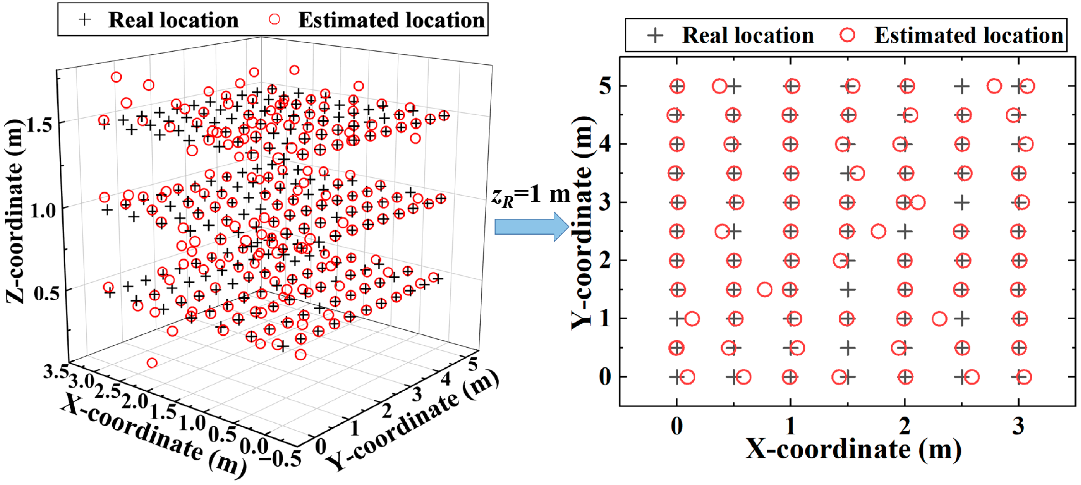
To evaluate the performance of the VLPO scheme at different locations for a tilted receiver,
Figure 9 shows an example of 3D positioning results in different receiving planes at the height of 0.5 m, 1 m, and 1.5 m. We fix the receiver polar angle
θ at 20° to ensure that the LOS channels between LEDs and PDs will not be blocked due to the receiver tilt. We assume the interval between PDs is 0.2 m and the standard derivation Δ
d of the ranging error is 0.025 m. The test locations are the same as in
Figure 5. On the left of
Figure 9, we observe that most of the estimated 3D coordinates are close to their corresponding real locations, thus verifying the effectiveness of the proposed VLPO scheme at different locations for a tilted receiver. Specifically, the mean 3D positioning error is 9.2 cm, 14.2 cm, and 20.9 cm at the height of 0.5 m, 1 m, and 1.5 m, respectively, from which the positioning accuracy is related to the height of the receiver. The reason is the same as in
Figure 5. On the right of
Figure 9, we show the corresponding 2D positioning results with a tilted receiver at the height of 1 m, wherein the mean positioning error is 10.7 cm. Besides, it can be observed that small positioning errors have a higher possibility to occur at the test locations below LEDs, e.g., where
xR = 0. This is because, when the receiver is tilted and located at the boundary of the considered indoor space with
xR = 0, multiple solutions of the estimated coordinates of PD
1 and PD
2 may stay close due to geometrical symmetry, thus their midpoints, i.e., the estimated locations of the receiver, have a higher chance to overlap, which potentially enhances the positioning accuracy at the test locations with
xR = 0.
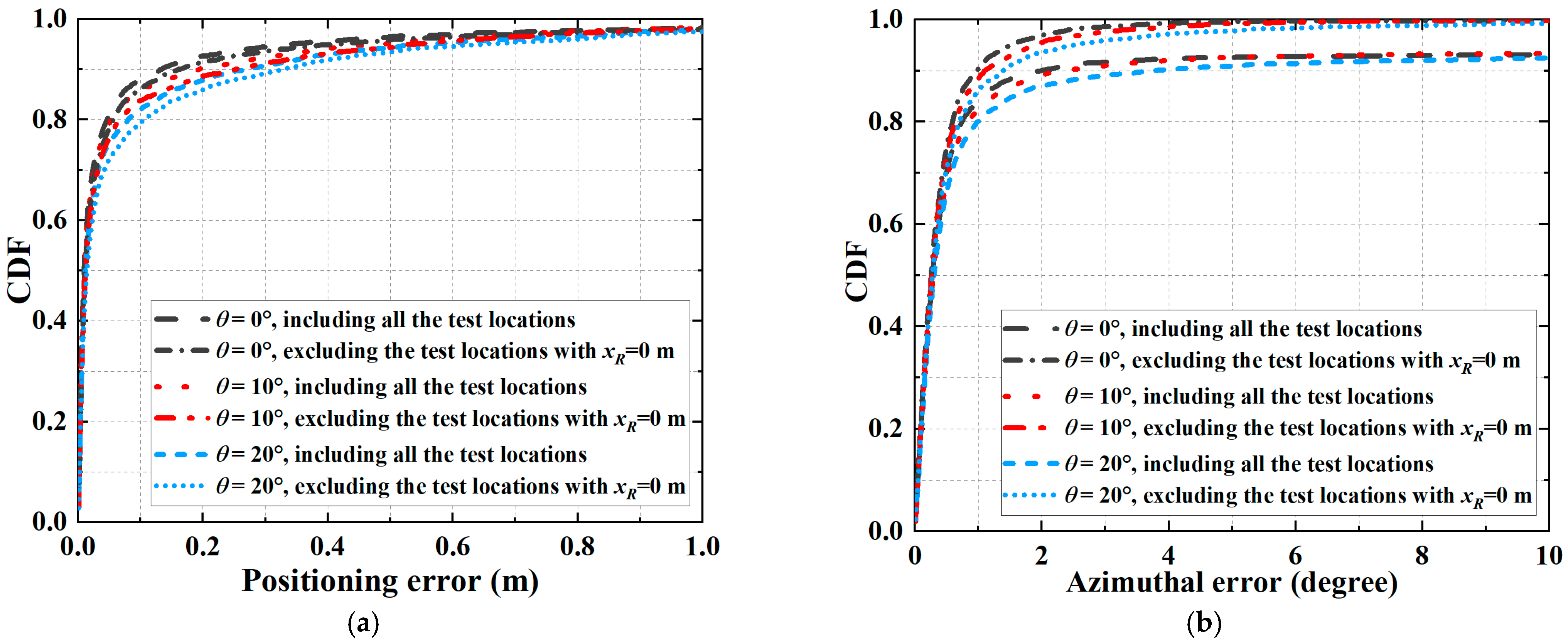
By considering the test locations in the receiving plane at the height of 1 m in
Figure 9,
Figure 10a shows the simulated CDFs of the 3D positioning errors at different locations. We assume the standard derivation Δ
d of the ranging error is 0.025 m and the interval
l between PDs is 0.5 m. We use different curves to represent the CDFs obtained by considering different polar angles with
θ to be 0°, 10°, and 20°. For a performance evaluation, we also plot the simulated CDF curves of the 3D positioning errors when excluding the test locations below LEDs with
xR = 0. We see that increasing the polar angle of a tilted receiver slightly degrades the overall positioning accuracy in the considered receiving plane. Specifically, when
θ is 0°, 10°, and 20°, the probability of achieving 3D positioning errors less than 20 cm is 92.7%, 90.3%, and 87.9%, respectively. In contrast, when excluding the test locations with
xR = 0, the probability of achieving 3D positioning errors less than 20 cm decreases to 91.5%, 88.7%, and 86.0% when
θ is 0°, 10°, and 20°, respectively. By comparison, smaller positioning errors tend to occur at the test locations below LEDs with
xR = 0, which confirms the conclusion in
Figure 9.
Corresponding to
Figure 10a,
Figure 10b plots the simulated CDFs of the azimuthal errors by considering the test locations in the receiving plane at the height of 1 m in
Figure 9. We assume the standard derivation Δ
d of the ranging error is 0.025 m and the interval
l between PDs is 0.2 m, and compare the CDFs obtained by considering different polar angles
θ of the tilted receiver. It is found that increasing
θ slightly degrades the overall orienteering accuracy in the considered receiving plane. Specifically, around 92.6%, 92.6%, and 90.9% of azimuthal errors are less than 5° when
θ is 0°, 10°, and 20°, respectively, thereby verifying the high orienteering accuracy of the VLPO scheme at different locations for a tilted receiver. Moreover, when excluding the test locations with
xR = 0, around 99.5%, 99.2%, and 97.7% of azimuthal errors are less than 5° when
θ is 0°, 10°, and 20°, respectively. Obviously, large azimuthal errors tend to occur at the test locations with
xR = 0. The reason lies in that, when the receiver tilts, although multiple solutions of the estimated coordinates of PD
1 and PD
2 may stay close due to geometrical symmetry as discussed in
Figure 9, the estimated azimuthal angles of the receiver are completely different and their sum is 180°, thus degrading the orienteering accuracy at the test locations with
xR = 0.
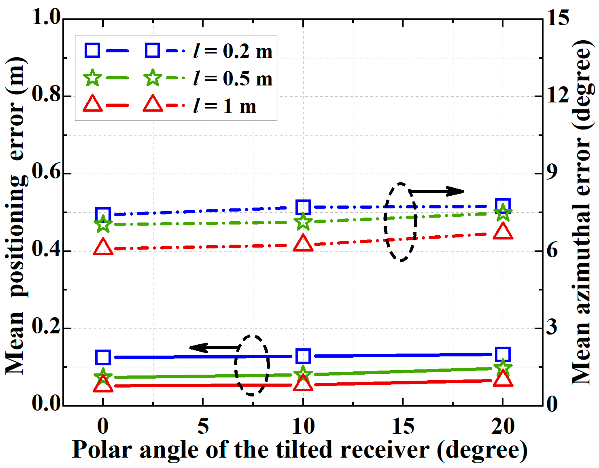
Finally, based on the test locations in
Figure 10,
Figure 11 compares the mean positioning errors and azimuthal errors versus different polar angles
θ of the tilted receiver. We assume Δ
d = 0.025 m. We set
θ = 0°, 10°, and 20°, and plot the mean positioning errors and azimuthal errors obtained by using different intervals
l between PDs. As can be seen, the change in the polar angle of the tilted receiver has only a small influence on both the positioning accuracy and the orienteering accuracy. Specifically, when
l is 0.2 m and
θ changes from 0° to 20°, the mean positioning error slightly increases from 12.5 cm to 13.3 cm, and the mean azimuthal error slightly increases from 7.4° to 7.7°. Therefore, the proposed VLPO scheme is robust to the variation of the receiver polar angle, and can achieve stable 3D positioning and orienteering accuracy with a tilted receiver.


