Article

Assessment of a New Trifocal Diffractive Corneal Inlay for Presbyopia Correction Using an Adaptive Optics Visual Simulator

by
Anabel Martínez-Espert
1,2,*,
Diego Montagud-Martínez
2,3,
Vicente Ferrando
3,
Walter D. Furlan
2 and
Juan A. Monsoriu
3
1
Clínica Aiken, Fundación Aiken, 46004 Valencia, Spain
2
Departamento de Óptica y Optometría y Ciencias de la Visión, Universitat de València, 46100 Valencia, Spain
3
Centro de Tecnologías Físicas, Universitat Politècnica de València, 46022 Valencia, Spain
*
Author to whom correspondence should be addressed.
Photonics 2022, 9(3), 135; https://doi.org/10.3390/photonics9030135
Submission received: 28 January 2022 / Revised: 21 February 2022 / Accepted: 24 February 2022 / Published: 25 February 2022
(This article belongs to the Special Issue Ocular Imaging for Eye Care)

Abstract

:
In this work, we analyze a proposal of a new intracorneal diffractive lens for presbyopia correction that could allow good, distance, intermediate and near vision. By using an adaptive optics visual simulator, we study the influence of two factors in the inlay performance: the spherical aberration (SA) and the potential errors of in thickness, induced in the manufacturing process. We show that the inlay through-the-focus imaging performance can be customized with the SA value, favoring either distance–intermediate or intermediate–near vision. Moreover, we found that with thickness variations of 10%, the inlay still maintains its trifocal nature.

1. Introduction

Presbyopia is a natural biological process that normally appears from the age of 40, that consists of a gradual loss of the ocular accommodation [1,2,3]. The difficulty of performing near-vision tasks at this age highlights the need for optical compensation use [2,3]. The rising life expectancy [1] and the increasing use of new technologies such as smartphones, tablets and computers [4] indicate that there will be a growing demand for solutions and resources to address this problem [1,5]. Ophthalmic lenses [6,7], contact lenses [6,7], and refractive surgery [6,8] are among the different solutions proposed to deal with presbyopia.
Another solution that involves minimally invasive and reversible surgery is to use corneal inlays (CIs) [3,9,10]. CIs are small biocompatible implants that are inserted into a pocket in the corneal stroma created using a femtosecond laser. Different optical principles were explored in the past to design CIs, including refraction [11,12,13,14] and small aperture inlays [15,16,17].
Nowadays, the only CI present in the market is the Kamra® (Acufocus Inc., Irvine, CA, USA). It is an opaque disc with a small central hole that produces extended depth of focus in the implanted eye. In this CI, thousands of micro-holes randomly distributed on its surface allow for the flow of nutrients in the corneal stroma [15,16,17]. The main shortcomings of the Kamra® include undesired diffractive effects produced by the micro-holes, as discussed in several studies [7,9,18,19,20].
The newest concept of CI is the diffractive corneal inlay (DCI) [21], which is based in the so-called “photon-sieve” concept [22]. A photon-sieve is an opaque plate having an array of holes located in the open zones of an amplitude Fresnel zone plate. Thus, it acts as a diffractive lens. In Ref. [21], it was demonstrated that the micro-perforations in the Kamra inlay (which necessary to nourish the corneal tissue and are randomly distributed) can be arranged to conform a photon-sieve like diffractive lens. In this way, the intrinsic negative effects produced by the diffraction through the micro-holes in the Kamra can be exploited as an advantage in our designs, creating a near vision focus for the eye. Moreover, the DCI can be customized to each patient by modifying the different design variables (such as the radius of the central hole; the diameter of the inlay; and the addition, number and distribution of micro-holes) [21,23].
In a recent paper [24], we proposed a new device in which the opaque surface of the DCI was replaced by a transparent material to obtain a pure phase (transparent) diffractive corneal inlay (coined PDCI). The result was the first trifocal CI. In it, the 0th diffraction order, generated by the central hole, provides the focus for intermediate distances, while the micro-holes in the periphery (located in the odd rings of the underlying zone plate) create the ±1 diffraction orders that provide two additional foci located symmetrically, one on each side of the 0th order. These two foci are intended for distance and near vision.
The aim of this work was to investigate the visual performance of the PDCI with different amounts of spherical aberration (SA) because it is well known that the SA can be used to increase the depth of focus in optical systems [25]. On the other hand, bearing in mind that, for practical purposes, the thicknesses of the original PDCI design could make the device too brittle, in this work we present a new design of PDCI with a thicker profile in order to increase its robustness, and we investigated its tolerance to potential errors in thickness during manufacture.

2. Materials and Methods

The diffractive structure of the previously proposed PDCI [24] consisted of a disk of 4.2 mm diameter with a central hole of 1.4 mm. The central hole was surrounded by 253 micro-holes of different diameters, distributed in 5 concentric rings (see Figure 1). In that case, the thickness of the PDCI was h = 3.5 μm just to produce a half wave optical path difference between the material and the micro-holes for the design wavelength (λ0 = 555 nm). To increase its mechanical resistance, in this work the PDCI thickness has been increased to a value that provides one wave and a half optical path difference between the material and the holes. The other geometrical parameters of the original proposal were maintained (see Figure 1). As detailed in Ref. [24], to design the PDCI we applied the photon sieve concept to obtain a trifocal diffractive lens, in which each focus corresponds to a different diffractive order.
The selected material for this new model was a hydrogel-based material of refractive index n = 1.458, which was used previously in other corneal inlays [3]. For its design, we assumed that the refractive index of the corneal stroma is nc = 1.376 [26]. With these values, the ideal inlay thickness was h = 3 λ0/2 (nnc) = 10.5 μm.
To study the new PDCI performance, an adaptive optics visual simulator (VAO, Voptica SL, Murcia, Spain) was employed [19,27]. By using a liquid crystal based on silicon (LCoS) RGB LED display, this clinical instrument allows for optical stimuli to be placed virtually at different distances from the eye. In front of the eye, the phase profile of any ophthalmic device can be simulated, including different values of optical aberrations for a pupil diameter of 4.5 mm [28,29,30]. For these pupils, different photopic luminance values are available: 40 cd/m2, 80 cd/m2 and 120 cd/m2. In this study, the visual performance of the PDCI was assessed with polychromatic light and medium photopic luminance (80 cd/m2). In addition, the effects of different amounts of SA (0.1 μm, 0 μm, −0.1 μm and ±1 μm thickness deviations in the PDCI manufacturing) were evaluated.
Two different stimuli were used: (1) a high-contrast tumbling E optotypes corresponding to a visual acuity (VA) of 0.4 logMAR units (0.4 decimal VA); and (2) a sinusoidal grating with a frequency of 12 cycles/degree, which roughly corresponds to a 0.4 logMAR test. In the experiments, the images were captured by an artificial eye, consisting on a CMOS sensor (EO-10012C LE, 8 bits, 3840 × 2748 pixels, and 6.41 × 4.59 mm) with an attached achromatic doublet (AC254-030-A-ML, Thorlabs Inc., Newton, NJ, USA).
The through-focus modulation transfer function (TF-MTF) was measured as the relative contrast of the images of a sinusoidal grating [31]. These images were virtually located at different vergences, in the range +1.00 D to −4.00 D, separated by 0.25 D. A pupil diameter of 4.5 mm was considered.

3. Results

We first evaluated the influence of different amounts SA (0.0 μm, +0.1 μm, and −0.1 μm) on the TF-MTFs given by the artificial eye with the PDCI shown in Figure 1. The results are shown in Figure 2. It can be noticed that with SA = 0.0 μm the PDCI (black line) produces a clear trifocal profile. However, positive and negative amounts of SA affect the intermediate focus in an opposite way. On the one hand, negative SA produces an overlapping of the intermediate and near foci, resulting in a bifocal profile with extended depth of focus for near-intermediate vision. On the other hand, positive SA produces an overlapping of the intermediate and far foci that produces a bifocal profile with extended depth of focus for distance-intermediate vision. Thus, the SA affects the refractive focus (intermediate vision) more than the diffractive foci (far and near).
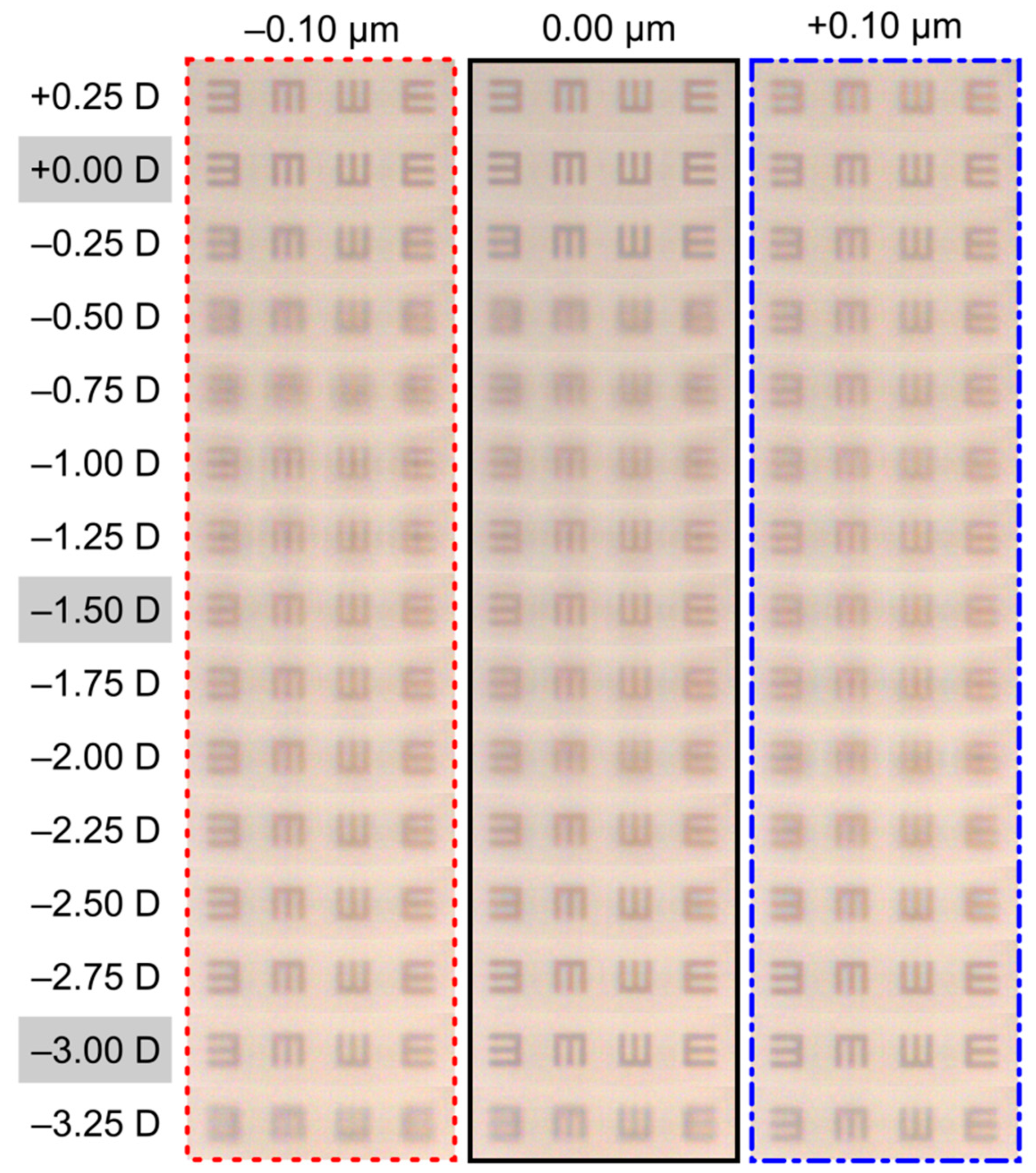
To provide more insights about the visual performance of the PDCI under the influence of different amounts of SA, images of a tumbling-E optotype corresponding to 0.4 logMAR VA and 0.0 logMAR VA were obtained. The results are shown in Figure 3 and Figure 4. It can be seen that the same effect obtained in Figure 2 is reproduced in both Figure 3 and Figure 4. In the last case, the visibility of the letters is lower, but it was included to show that the extended bifocal profile obtained with positive and negative values of SA are also visible with letters of 0.0 logMAR VA.
In order to evaluate the manufacturing tolerance to deviations from the ideal thickness of 10.5 µm, the TF-MTFs results for two PDCIs with a difference of ±1.0 µm thickness are shown in Figure 5. Note that in both cases, the trifocal profile is preserved. For the PDCI of thickness h = 9.5 µm, the visibility of the letters is very similar for all three foci (dotted line). For the PDCI of thickness h = 11.5 µm, the intermediate focus improves with respect to the other two foci (continuous green line). Figure 6 shows the images captured at the foci (far, intermediate and near) of tumbling E’s, corresponding to 0.0 logMAR, 0.2 logMAR and 0.4 logMAR. It can be seen that the results of the TF-MTFs and the images at the foci are highly correlated.

4. Discussion

In recent years, there has been increasing interest in CIs for the correction of presbyopia, mainly because it is an effective, reversible and minimally invasive therapy [3,9,10]. New models of CIs can benefit from advances in new biocompatible materials and improvements in laser technology [10]. In this work, we employed an adaptive optics visual simulator to investigate, for the first time, the influence of two important parameters that could affect the PDCI visual performance: its robustness against thickness variations that could arise during manufacturing, and the SA of the eye. Adaptive optics visual simulators have proven to be very effective tools for designing and non-invasive testing of ophthalmic optical elements, including CIs [24,25].
We found that SA has important effects on the image performance of the PDCI. As shown in Figure 2, Figure 3 and Figure 4, different values of SA affect mainly the intermediate focus. This is a relevant result that could be of interest to surgeons for customized treatments in patients with specific vision needs, given that certain amount of SA can be induced during the implant surgery [32]. Moreover, it presents the possibility to design new PDCIs in which the distribution of the micro-holes will follow a fourth-order polynomial along the radial coordinate to compensate for the effect of different amounts of SA in the eye [21]. Nevertheless, the reader should be aware that the estimation of the SA induced in the operation is not an easy task because there are several critical factors involved that could not be accurately estimated in a first approach (corneal biomechanics, surgical instrumentation and technique, etc.).
Another important parameter that should be taken into account in the design of CIs is their thickness because, on the one hand, a CI of a few microns facilitates the flow of nutrients through the inlay and minimizes the risk of corneal inflammation; however, a very thin CI could be difficult to manufacture and to handle (the Kamra® inlay is one example). On the other hand, a thick DCI such as the one here proposed will be more robust and reduce possible thickness errors in manufacturing. However, the risk of inducing corneal thickness variations and epithelial decompensation must be evaluated.
Finally, it is important to remark that, although promising, the results of this study were obtained with a virtual PDCI programmed in a visual simulator under medium photopic luminance. Therefore, they cannot be extrapolated to clinical conditions directly. Future studies of DCIs with the VAO system will be performed with real patients and different lighting conditions before proceeding with the construction and clinical trials with DCI prototypes.

5. Conclusions

A new design of the trifocal PDCI was presented, and its performance under the influence of SA and thickness variations due to potential manufacturing errors was studied. We found that the SA extends the focal depth of the intermediate focus by a partial overlapping with the far focus or near focus, depending on the sign of the SA. Considering that different amounts of SA can be induced by the laser in inlay surgery, this would allow one to obtain a customized focal distribution that suits the visual needs of each patient. Regarding the influence of thickness error, it has been shown that with thickness variations of ± 1 µm, the inlay still preserves the PDCI trifocality.

Author Contributions

Conceptualization, W.D.F.; Formal analysis, D.M.-M., V.F. and W.D.F.; Funding acquisition, J.A.M.; Methodology, A.M.-E., D.M.-M. and V.F.; Project administration, J.A.M.; Software, A.M.-E., D.M.-M. and V.F.; Supervision, W.D.F. and J.A.M.; Validation, W.D.F. and J.A.M.; Writing—original draft, D.M.-M. and V.F.; Writing—review and editing, A.M.-E., D.M.-M. and V.F. All authors have read and agreed to the published version of the manuscript.

Funding

This work was supported by Ministerio de Ciencia e Innovación, Spain [PID2019-107391RB-I00] and by Generalitat Valenciana, Spain [PROMETEO/2019/048]. D.M.-M. also acknowledges the Margarita Salas grant from the Ministerio de Universidades, Spain, funded by the European Union-Next-Generation EU.

Institutional Review Board Statement

Not applicable.

Informed Consent Statement

Not applicable.

Data Availability Statement

The data that support the findings of this study are available from the corresponding author, A.M.-E., upon reasonable request.

Conflicts of Interest

The authors declare no conflict of interest.

References

  1. Fricke, T.R.; Tahhan, N.; Resnikoff, S.; Papas, E.; Burnett, A.; Ho, S.M.; Naduvilath, T.; Naidoo, K.S. Global prevalence of presbyopia and vision impairment from uncorrected presbyopia: Systematic review, meta-analysis, and modelling. Ophthalmology 2018, 125, 1492–1499. [Google Scholar] [CrossRef] [PubMed]
  2. Charman, W.N. Developments in the correction of presbyopia I: Spectacle and contact lenses. Ophthalmic Physiol. Opt. 2014, 34, 8–29. [Google Scholar] [CrossRef] [PubMed]
  3. Charman, W.N. Developments in the correction of presbyopia II: Surgical approaches. Ophthalmic Physiol. Opt. 2014, 34, 397–426. [Google Scholar] [CrossRef] [PubMed]
  4. Bababekova, Y.; Rosenfield, M.; Hue, J.E.; Huang, R.R. Font size and viewing distance of handheld smart phones. Optom. Vis. Sci. 2011, 88, 795–797. [Google Scholar] [CrossRef] [PubMed] [Green Version]
  5. Wang, C.; Wang, X.; Jin, L.; Tang, B.; Zhu, W.; Zhang, G.; Chen, T.; McAneney, H.; Kassalow, J.; Congdon, N. Influence of presbyopia on smartphone usage among Chinese adults: A population study. Clin. Exp. Ophthalmol. 2019, 47, 909–917. [Google Scholar] [CrossRef]
  6. Wolffsohn, J.S.; Davies, L.N. Presbyopia: Effectiveness of correction strategies. Prog. Retin. Eye Res. 2019, 68, 124–143. [Google Scholar] [CrossRef] [Green Version]
  7. Charman, W.N. Non-surgical treatment options for presbyopia. Expert Rev. Ophthalmol. 2018, 13, 219–231. [Google Scholar] [CrossRef]
  8. Hossain, P.; Barbara, R. The future of refractive surgery: Presbyopia treatment, can we dispense with our glasses? Eye 2021, 35, 359–361. [Google Scholar] [CrossRef]
  9. Lindstrom, R.L.; Macrae, S.M.; Pepose, J.S.; Hoopes, P.C. Corneal inlays for presbyopia correction. Curr. Opin. Ophthalmol. 2013, 24, 281–287. [Google Scholar] [CrossRef]
  10. Moarefi, M.A.; Bafna, S.; Wiley, W. A review of presbyopia treatment with corneal inlays. Opthamol. Ther. 2017, 6, 55–65. [Google Scholar] [CrossRef] [Green Version]
  11. Beer, S.M.C.; Werner, L.; Nakano, E.M.; Santos, R.T.; Hirai, F.; Nitschke, E.J.; Francesconi Benicio, C.; Campos, M.S. A 3-year follow-up study of a new corneal inlay: Clinical results and outcomes. Br. J. Ophthalmol. 2020, 104, 723–728. [Google Scholar] [CrossRef] [PubMed]
  12. Limnopoulou, A.N.; Bouzoukis, D.I.; Kymionis, G.D.; Panagopoulou, S.I.; Plainis, S.; Pallikaris, A.I.; Feingold, V.; Pallikaris, I.G. Visual outcomes and safety of a refractive corneal inlay for presbyopia using femtosecond laser. J. Refract. Surg. 2013, 29, 12–19. [Google Scholar] [CrossRef] [PubMed]
  13. Malandrini, A.; Martone, G.; Menabuoni, L.; Catanese, A.M.; Tosi, G.M.; Balestrazzi, A.; Corsani, C.; Fantozzi, M. Bifocal refractive corneal inlay implantation to improve near vision in emmetropic presbyopic patients. J. Cataract Refract. Surg. 2015, 41, 1962–1972. [Google Scholar] [CrossRef] [PubMed]
  14. Garza, E.B.; Gomez, S.; Chayet, A.; Dishler, J. One-year safety and efficacy results of a hydrogel inlay to improve near vision in patients with emmetropic presbyopia. J. Refract. Surg. 2013, 29, 166–172. [Google Scholar] [CrossRef] [Green Version]
  15. Waring, G.O. Correction of presbyopia with a small aperture corneal inlay. J. Refract. Surg. 2011, 27, 842–845. [Google Scholar] [CrossRef]
  16. Vilupuru, S.; Lin, L.; Pepose, J.S. Comparison of contrast sensitivity and through focus in small-aperture inlay, accommodating intraocular lens, or multifocal intraocular lens subjects. Am. J. Ophthalmol. 2015, 160, 150–162. [Google Scholar] [CrossRef]
  17. Vukich, J.A.; Durrie, D.S.; Pepose, J.S.; Thompson, V.; van de Pol, C.; Lin, L. Evaluation of the small-aperture intracorneal inlay: Three-year results from the cohort of the US Food and Drug Administration clinical trial. J. Cataract Refract. Surg. 2018, 44, 541–556. [Google Scholar] [CrossRef] [PubMed]
  18. Seyeddain, O.; Bachernegg, A.; Riha, W.; Rückl, T.; Reitsamer, H.; Grabner, G.; Dexl, A.K. Femtosecond laser–assisted small-aperture corneal inlay implantation for corneal compensation of presbyopia: Two-year follow-up. J. Cataract Refract. Surg. 2013, 39, 234–241. [Google Scholar] [CrossRef]
  19. Tabernero, J.; Schwarz, C.; Fernández, E.J.; Artal, P. Binocular visual simulation of a corneal inlay to increase depth of focus. Investig. Ophthalmol. Vis. Sci. 2011, 52, 5273–5277. [Google Scholar] [CrossRef]
  20. Plainis, S.; Petratou, D.; Giannakopoulou, T.; Radhakrishnan, H.; Pallikaris, I.G.; Charman, W.N. Small-aperture monovision and the Pulfrich experience: Absence of neural adaptation effects. PLoS ONE 2013, 8, e75987. [Google Scholar] [CrossRef] [Green Version]
  21. Furlan, W.D.; García-Delpech, S.; Udaondo, P.; Remón, L.; Ferrando, V.; Monsoriu, J.A. Diffractive corneal inlay for presbyopia. J. Biophotonics 2017, 10, 1110–1114. [Google Scholar] [CrossRef] [PubMed]
  22. Kipp, L.; Skibowski, M.; Johnson, R.L.; Berndt, R.; Adelung, R.; Harm, S.; Seemann, R. Sharper images by focusing soft X-rays with photon sieves. Nature 2001, 414, 184–188. [Google Scholar] [CrossRef] [PubMed]
  23. Montagud-Martínez, D.; Ferrando, V.; Monsoriu, J.A.; Furlan, W.D. Proposal of a new diffractive corneal inlay to improve near vision in a presbyopic eye. Appl. Opt. 2020, 59, D54–D58. [Google Scholar] [CrossRef] [PubMed]
  24. Furlan, W.D.; Montagud-Martínez, D.; Ferrando, V.; García-Delpech, S.; Monsoriu, J.A. A new trifocal corneal inlay for presbyopia. Sci. Rep. 2021, 11, 6620. [Google Scholar] [CrossRef]
  25. Leray, B.; Cassagne, M.; Soler, V.; Villegas, E.A.; Triozon, C.; Perez, G.M.; Letsch, J.; Chapotot, E.; Artal, P.; Malecaze, F. Relationship between induced spherical aberration and depth of focus after hyperopic LASIK in presbyopic patients. Ophthalmology 2015, 122, 233–243. [Google Scholar] [CrossRef]
  26. Liou, H.-L.; Brennan, N.A. Anatomically accurate, finite model eye for optical modeling. J. Opt. Soc. Am. A 1997, 14, 1684–1695. [Google Scholar] [CrossRef]
  27. VAO. Voptica. Available online: https://voptica.com/vao/ (accessed on 29 September 2021).
  28. Manzanera, S.; Prieto, P.M.; Ayala, D.B.; Lindacher, J.M.; Artal, P. Liquid crystal Adaptive Optics Visual Simulator: Application to testing and design of ophthalmic optical elements. Opt. Express 2007, 15, 16177–16188. [Google Scholar] [CrossRef]
  29. Hervella, L.; Villegas, E.A.; Robles, C.; Artal, P. Spherical aberration customization to extend the depth of focus with a clinical adaptive optics visual simulator. J. Refract. Surg. 2020, 36, 223–229. [Google Scholar] [CrossRef]
  30. Fernández, E.J.; Prieto, P.M.; Artal, P. Wave-aberration control with a liquid crystal on silicon (LCOS) spatial phase modulator. Opt. Express 2009, 17, 11013–11025. [Google Scholar] [CrossRef]
  31. Calatayud, A.; Remón, L.; Martos, J.; Furlan, W.D.; Monsoriu, J.A. Imaging quality of multifocal intraocular lenses: Automated assessment setup. Ophthal. Physiol. Opt. 2013, 33, 420–426. [Google Scholar] [CrossRef]
  32. Rahmania, N.; Salah, I.; Rampat, R.; Gatinel, D. Clinical Effectiveness of Laser-Induced Increased Depth of Field for the Simultaneous Correction of Hyperopia and Presbyopia. J. Refract. Surg. 2021, 37, 16–24. [Google Scholar] [CrossRef] [PubMed]
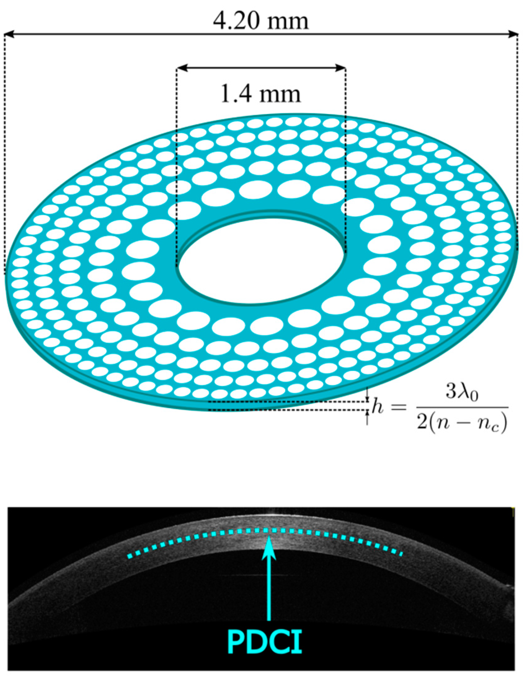
Figure 1. Three-dimensional representation of the new PDCI design. The PDCI material (in blue) is a hydrogel of refractive index n = 1.458, and a representation of the location of the PDCI in the corneal stroma.
Photonics 09 00135 g001
Figure 2. Relative contrast (TF-MTF) provided by the PDCI with different SA values for a pupil size of 4.5 mm. Note that the far, intermediate and near foci are located at 0.0 D, −1.5 D and −3.0 D, respectively.
Photonics 09 00135 g002
Figure 3. Through-the-focus images of a tumbling E optotype (VA = 0.4 logMAR) provided by the PDCIs with the values of SA as in Figure 2. Shaded vergences indicate the position of the foci.
Photonics 09 00135 g003
Figure 4. Through-the-focus images of a tumbling E optotype (VA = 0.0 logMAR) provided by the PDCIs with the same values of SA as in Figure 2. Shaded vergences indicate the position of the foci.
Photonics 09 00135 g004
Figure 5. Relative contrast (TF-MTF) provided by the PDCI with 10.5 ± 1 µm thickness for a pupil size of 4.5 mm.
Photonics 09 00135 g005
Figure 6. Images of 0.0 logMAR, 0.2 logMAR and 0.4 logMAR optotypes obtained at the far, intermediate and near foci.
Photonics 09 00135 g006
Publisher’s Note: MDPI stays neutral with regard to jurisdictional claims in published maps and institutional affiliations.