Article

Trade-Off Asymmetric Profile for Extended-Depth-of-Focus Ocular Lens

by
Lenny A. Romero
1,
Andrés G. Marrugo
2 and
María S. Millán
3,*
1
Facultad de Ciencias Básicas, Universidad Tecnológica de Bolívar, Cartagena 130010, Colombia
2
Facultad de Ingeniería, Universidad Tecnológica de Bolívar, Cartagena 130010, Colombia
3
Terrassa School of Optics and Optometry, Universitat Politècnica de Catalunya-BarcelonaTech, 08222 Terrassa, Spain
*
Author to whom correspondence should be addressed.
Photonics 2022, 9(2), 119; https://doi.org/10.3390/photonics9020119
Submission received: 19 December 2021 / Revised: 11 February 2022 / Accepted: 17 February 2022 / Published: 19 February 2022
(This article belongs to the Special Issue Ocular Imaging for Eye Care)

Abstract

:
We explore the possibility of extending the depth of focus of an imaging lens with an asymmetric quartic phase-mask, while keeping the aberration within a relatively low level. This can be intended, for instance, for ophthalmic applications, where no further digital processing can take place, relying instead on the patient’s neural adaptation to their own aberrations. We propose a computational optimization method to derive the design-strength factor of the asymmetric profile. The numerical and experimental results are shown. The optical experiment was conducted by means of a modulo-2π phase-only spatial light modulator. The proposed combination of the asymmetric mask and the lens can be implemented in a single refractive element. An exemplary case of an extended-depth-of focus intraocular lens based on the proposed element is described and demonstrated with a numerical experiment.

1. Introduction

Defocus is one of the most common sources of image degradation in the optical imaging system of the eye. An image with maximum lateral resolution is perceived when the human sensor is placed at the optical conjugate plane of the object or, at least, within an axial range of the image space; this is known as depth of focus (DOF). An analogous axial range can be measured in the object space, called depth of field, where objects placed at different distances from the optical system are imaged with maximum sharpness. In human vision, the DOF can be considered to provide a perceptual tolerance for relatively small focus errors. This perceptual tolerance is certainly desirable, and is common to all physiological feedback control systems [1].
Image quality rapidly decreases outside the DOF. There has been a variety of approaches aimed at resolving this disadvantage by extending the DOF, which in turn, enlarges the depth of field. Applications oriented to digital imaging by cameras, and to ophthalmic vision correction, are reviewed in [2].
A large number of diffractive optical elements (DOEs), refractive components, and multifocal lenses has been designed to mitigate defocus and obtain DOF extension in imaging systems. For instance, a simple approach consists of co-axially combining several lenses that are spatially multiplexed and displayed on a liquid-crystal device [3]. The axial irradiance distribution produced by each lens overlaps with the next, thus resulting an extended DOF. Other solutions, such as a combination of an asymmetric phase-mask (APM) with an imaging lens [4,5], involve the introduction of a certain amount of aberration that stays nearly constant along the axial segment, thus extending the DOF. Typically, a digital deconvolution in a post-processing stage is required to further improve the output result and obtain a sharp image.
In this work, we explore the possibility of extending the DOF of an imaging lens with an optical element such as the APM, while keeping the aberration within a relatively low level so that no further posterior digital processing is needed. Although a perfectly clear and in-focus retinal image is ideally present only when an object is optically conjugated with the retina itself, a slightly defocused image will also be interpreted this way by the brain, as long as it is positioned within the optical extension of the DOF. This hypothesis relies on the neural adaptation wherein the human brain compensates for the eye’s optical aberrations [6,7], and even has a neural mechanism that compensates for the optical differences between the eyes [8]. Encouraged by the demand for presbyopia compensation in ophthalmic optics and the results abundantly reported showing a variety of elements—such as quartic phase-mask [4], light sword [9], peacock eye [10], small aperture [11], a combination of fourth- and sixth-order spherical aberration [12], and line-umbilical multifocal-wavefront-based elements [13], to mention a few—we study the trade-off between extending the DOF with the quartic APM [4] and a decrease in image quality. We propose a numerical optimization scheme that could be used as a design criterion for ophthalmic imaging systems that cannot admit further digital processing.
We describe the computational optimization method and show numerical as well as experimental results. The optical experiment was conducted by means of a modulo-2 π phase-only spatial light modulator (SLM). For this reason, the computed trade-off asymmetric profile displayed on the SLM looked like a pure diffractive optical element, with its characteristic distribution of echelettes or diffractive steps. The combination of an asymmetric mask and a monofocal lens can be implemented in a single optical element. Its prototyping can be mechanized with smooth curvature onto the ophthalmic lens’ surfaces, which would show no discrete diffractive steps. This property would clearly simplify the manufacturing process of the refractive element, and reduce the wavelength dependence of its performance in comparison with a DOE.

2. Methods

2.1. Theoretical Background: The Generalized Pupil Function of a Thin Lens and Defocus

In imaging systems, defocus results in a spatial low-pass filter effect. Such an effect can be described through the optical-transfer function (OTF), which, in the case of a single thin lens, corresponds to the scaled autocorrelation of the generalized pupil function defined by [14]:
P ( x , y ) = Q ( x , y ) φ ( x , y )
where ( x , y ) are the pupil-plane spatial coordinates, Q ( x , y ) is the physical aperture, and φ ( x , y ) represents the phase transformation at the plane of the pupil; this can be expressed as φ ( x , y ) = exp [ i k W ( x , y ) ] , where W ( x , y ) is the wave aberration function, k = 2 π / λ , λ is the optical wavelength, and i is the imaginary unit. For the sake of simplicity, in the following, we discuss a one-dimensional (1-D) imaging model.
When an aberration such as defocus is introduced, W ( x ) has a quadratic form:
W ( x ) = W 20 ( x R ) 2
where R is the radius in case of a lens with a circular aperture. Hopkins’ defocus coefficient W 20 determines the severity of the defocus aberration [15] and is given by:
W 20 = R 2 2 ( 1 z + 1 z 1 f ) ,
where z is the distance from the object plane to the lens, z is the distance from the lens to the image plane, and f is the focal length. When the object and image planes conjugate optically through the thin lens, the imaging condition is fulfilled, that is,
1 z + 1 z = 1 f     ,
and W 20 = 0 . The DOF is the axial range in the image space z where the image appears sharp, i.e., with maximum lateral resolution. Frequently, the coefficient W 20 is translated into a phase misfocus factor ψ ,
ψ = k W 20 ,
so that, the 1-D generalized pupil function of the thin lens can be written as:
P ( ψ ; x ) = Q ( x ) exp [ i ψ ( x R ) 2 ] .

2.2. Asymmetric Phase-Mask Family to Extend the Depth of Focus

Castro and Ojeda [4] demonstrated that there is a family of asymmetric phase-masks that, when placed in the pupil of an imaging system, are useful for extending the axial range of high, lateral resolution (either depth of field, if measured in the object space, or DOF, if measured in the image space). Their generalized pupil function takes the form:
P a ( x ) = Q ( x ) exp [ i 2 π α   sgn ( x ) | x R | n ] ,
where α is a strength factor that represents the maximum optical path difference in wavelength units, introduced by the mask, and n is a positive integer number that denotes the order of the phase profile. Typically, the strength factor α is a positive number. No asymmetric mask would be introduced for the trivial case α = 0 . The asymmetry of the phase-mask is introduced in Equation (7) through the signum function, defined as sgn ( x ) = + 1   for   x > 0 ,   sgn ( x ) = 1   for   x < 0 . Since the masks are phase-only, the light-gathering capability of the imaging system is not affected. Moreover, since the whole pupil aperture is covered by the mask, the frequency content is preserved. However, these properties are achieved at the expense of a decline in the image quality, which is also revealed in a decay of the modulation transfer function (MTF) curves. As the authors pointed out, the image degradation from the in-focus to the out-of-focus images is slower for the phase-masks with low orders ( n = 4 , 5 , 6 ) than for those with high orders (for example, n = 9 ,   10 ,   and   12 ) . This fact led them to propose digital image restoration procedures for further image enhancement [4]. According to the authors, “the asymmetric phase-mask of the order n = 4 is a good choice because the resulting MTFs have low variations with focus error. Additionally, the ripples (along the main curve of the MTF) are reduced” [4]. For this reason, we consider a quartic-order-phase profile hereafter in this work.

2.3. Image Quality Metrics

The optical-transfer function (OTF) of an imaging system allows a complete mathematical description of the image quality in terms of the spatial frequency u . The 1-D OTF H ( u ) of a single lens that uses incoherent illumination can be expressed as the normalized autocorrelation function of the generalized pupil function [14]. We assume a binary aperture Q ( x ) , which equals 1 within the pupil and 0 outside. In the presence of severe defocus, that is, when W 20 λ , such a 1-D OTF can be approximated by H ( u ) = sin c ( 4 π W 20 z u / R ) , which explains the spectral low-pass filtering effect of defocus [2]. The OTF can be calculated as the Fourier transform of the impulse response h ( x ) , where x represents the image-plane spatial coordinate. For incoherent systems, the impulse response is, in turn, the square of the Fourier transform of the generalized pupil function. Therefore, the 1-D OTF of a single lens imaging system affected by defocus can be expressed as:
H ( ψ ; u ) = { h ( ψ ; z ) } = { | { P ( ψ ; x ) } | 2 } .
The MTF, which is the absolute value of the OTF, | H ( u ) | , provides a means to quantify the image quality in terms of the magnitude response of the optical system to sinusoids of different spatial frequencies. For imaging systems limited by diffraction and aberrations, this useful metric reveals the general decrease in contrast or modulation depth in the image, with increasing frequency [14,16].
The impulse response h ( x ) is equal to the image of an ideal point object, generally known as the point-spread function (PSF). The imaging quality of the optical system can be evaluated through PSF-based metrics. In particular, many PSF descriptors are widely used in visual optics (e.g., Strehl ratio, light-in-the-bucket) [17,18]. Demenikov [19] introduced a PSF shape descriptor based on kurtosis to evaluate the imaging quality of systems affected by aberrations, in particular, defocus ψ . The 1-D kurtosis measure (KM) [19] of the actual PSF h a is given by:
KM = κ ( h a ( ψ ; x ) ) κ ( h d l ( 0 ; x ) ) ,
where the kurtosis κ ( s ) = μ 4 ( s ) / μ 2 2 ( s ) is defined from the fourth and second central moments, μ 4   and   μ 2 , of the distribution s . From Equation (9), KM is normalized to the in-focus and diffraction-limited impulse response represented by h d l . Demenikov applied KM (Ec. 9) to evaluate the restored PSF obtained after mitigating defocus by means of cubic and quartic phase-masks [19]; in this paper, however, we will use KM to evaluate the imaging quality of the DOF extension produced by a monofocal lens combined with an APM.

2.4. Phase Mask Trade-Off

Unlike a hybrid optical-digital imaging system, we aim for an optimal trade-off between the extended DOF and image quality for an imaging system—such as the eye—in which digital restoration is not possible. This way, we aim for a system that is as invariant as possible to defocus, but at the same time, preserves the image quality along the DOF. This criterion for optimization has been considered by other authors [20]. To this end, we will use a combination of a single thin lens with a quartic-order ( n = 4 ) APM profile P a ( x ) (Equation (7)), and propose an optimization scheme based on two terms, E 1 ( α )   and   E 2 ( α ) , for selecting the appropriate strength factor α that achieves the best trade-off.
On the one hand, invariance to defocus involves a kind of constancy in the MTFs along the axis in the image space. Let us define the term E 1 ( α ) that, for a given α , computes the accumulated square differences between the defocused MTF and the in-focus MTF along the axis in the image space:
E 1 ( α ) = k l [ | H α ( ψ k ; u l ) | | H α ( 0 ; u l ) | ] 2 l [ H α ( 0 ; u l ) ] 2 ,
where l covers, with uniform sampling, the discrete space-frequency domain normalized to the diffraction-limited cutoff frequency. The axial range in the image space is discretized uniformly in k defocus levels ψ k . The extreme values of k must be set to contain the pursued DOF extension, which is typically expressed in terms of the design focal length f . For example, an axial segment ranging from 0.6 f   to   1.6 f , in f / 10 steps, is to be considered in Section 3. The in-focus MTF for a strength factor α is | H α ( 0 ; u ) | . The denominator of Equation (10) has been introduced for normalization purposes. If E 1 ( α ) is minimized, the imaging system will be as little affected by defocus as possible. Ideally, if E 1 ( α ) were zero, the imaging performance along the DOF segment would be equal to that of the in-focus plane.
On the other hand, we aim to achieve good image quality by reducing the impact of blur with respect to the aberration-free imaging system. To this end, let us define the term E 2 ( α ) that computes, in the in-focus plane, the square difference between the MTF of the imaging system for a given α and the diffraction-limited MTF | H d l ( 0 ; u ) | ,
E 2 ( α ) = l [ | H α ( 0 ; u l ) | | H d l ( 0 ; u l ) | ] 2 l [ H d l ( 0 ; u l ) ] 2 .
Overall, the goal is to extend the DOF as much as possible with little degradation of the in-focus image quality. This can be accomplished mathematically by means of the global minimization function or residual
arg min α | β E 1 ( α ) ( 1 β ) E 2 ( α ) | ,
where β [ 0 , 1 ] defines the relative weight of either extending the DOF or preserving in-focus image quality.
The method outlined so far leads us to use the asymmetric quartic phase-mask for extending the DOF of a simple monofocal lens in ophthalmic optics. Despite the fact that the proposed phase distribution can be implemented using refractive optics, we will use programmable diffractive optics in our experiments with an SLM for evaluating the concept. Concerning the potential applications of our work to the human vision system, the in-focus plane is assumed to be coincident with the far-focus plane, that is, the focus plane corresponding to the vision of objects placed at a long distance from the observer. In our experiments, we observed that small variations around β = 0.5 (less than 10%) did not produce significant differences. We tentatively set β = 0.6 , meaning that extending the DOF is slightly preferred over the in-focus image quality, while still assuming that the visual system can tolerate the distortion. This parameter β , however, can be tuned according to another criterion.

3. Experiments and Results

We tested our optimization method with numerical simulations for an imaging system consisting of a diffractive Fresnel lens (FL) combined with an APM, which we were able to replicate using a phase-only spatial light modulator (SLM) in our experimental setup. We optimized the APM strength factor for the considered imaging system and validated the simulation results through an experiment conducted in the optical setup shown in Figure 1. We explored the potential applicability of such results to the design of an extended-depth-of-focus (EDOF) intraocular lens (IOL).

3.1. Numerical Simulation

We computationally simulated a diffractive FL with circular pupil diameter L = 8.64   mm , f = 500   mm focal length, illuminated by the incoherent light of wavelength λ = 632   nm . The dimension L was equal to the aperture of the SLM used in the experimental implementation, which covered 1080 pixels of 8-micron pitch. For a distant object ( z 0 = ), the in-focus image plane was located at z 0 = 500   mm from the lens. We considered a discrete axial segment z 0 in the image space to include both positive and negative defocus values. It ranged from 0.6 f   to   1.6 f , in f / 10 steps, which resulted in the following series of eleven image plane positions z and their corresponding defocus W 20 coefficients:
z = { 300 ,   350 ,   400 ,   450 ,   500 ,   550 ,   600 ,   650 ,   700 ,   750 ,   800 }   mm , W 20 = { 19.7 ,   12.7 ,   7.4 ,   3.3 ,   0 , 2.7 , 4.9 , 6.8 , 8.4 , 9.8 , 11.1 } λ ,
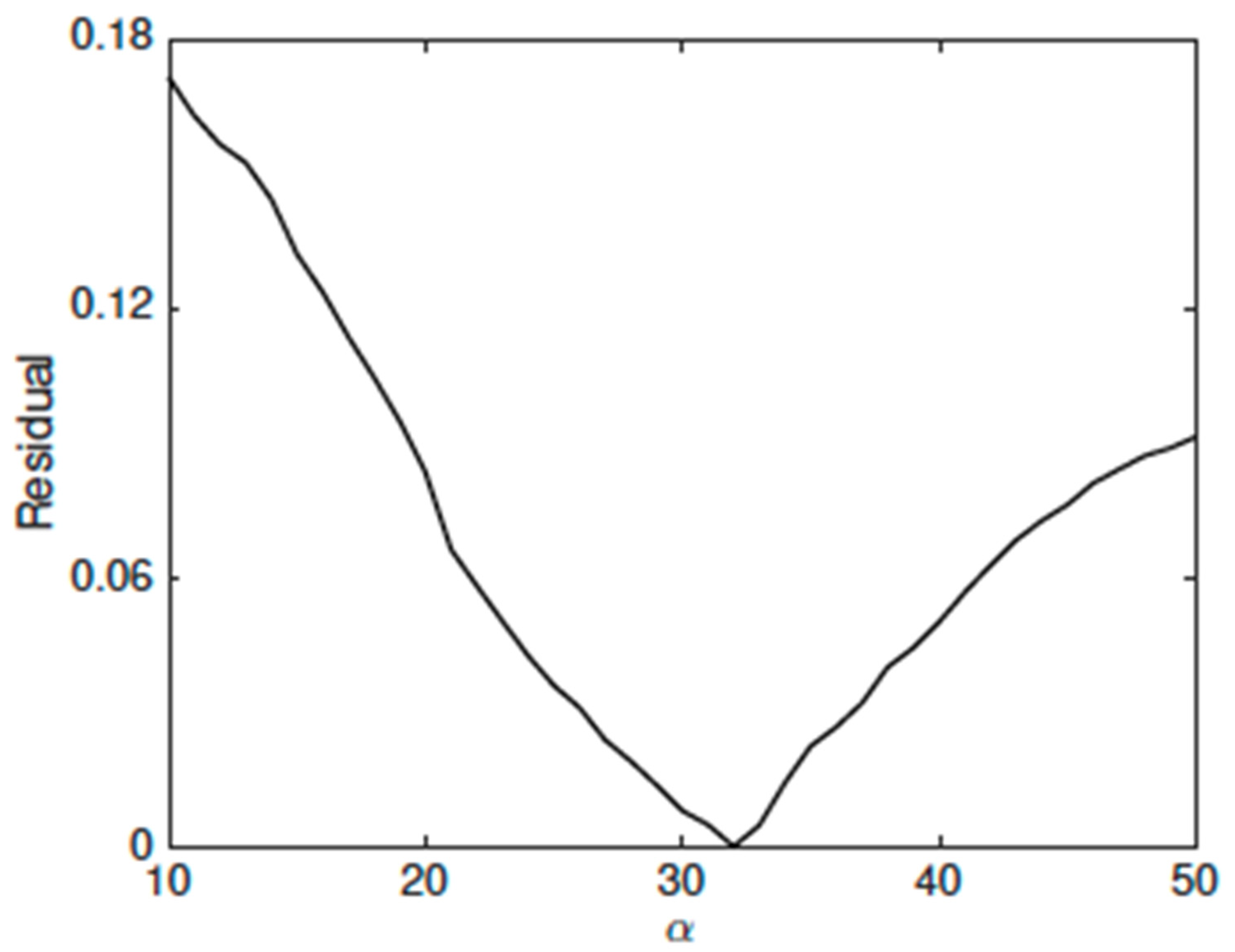
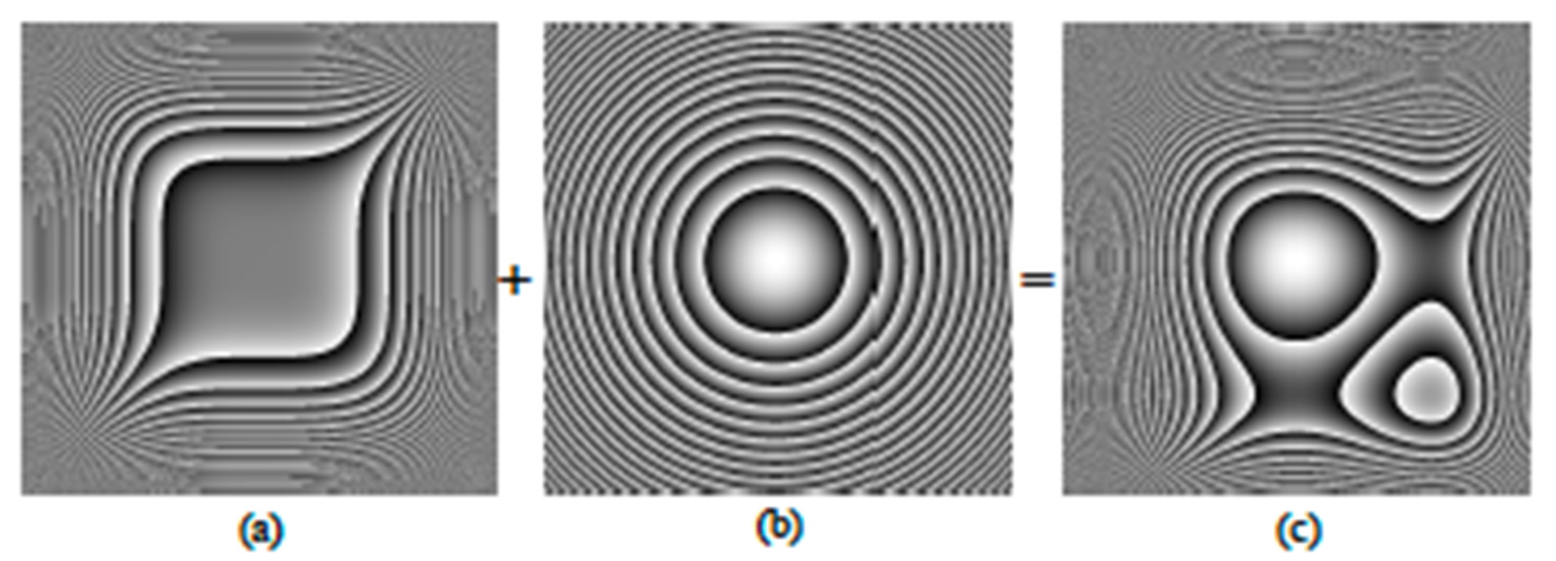
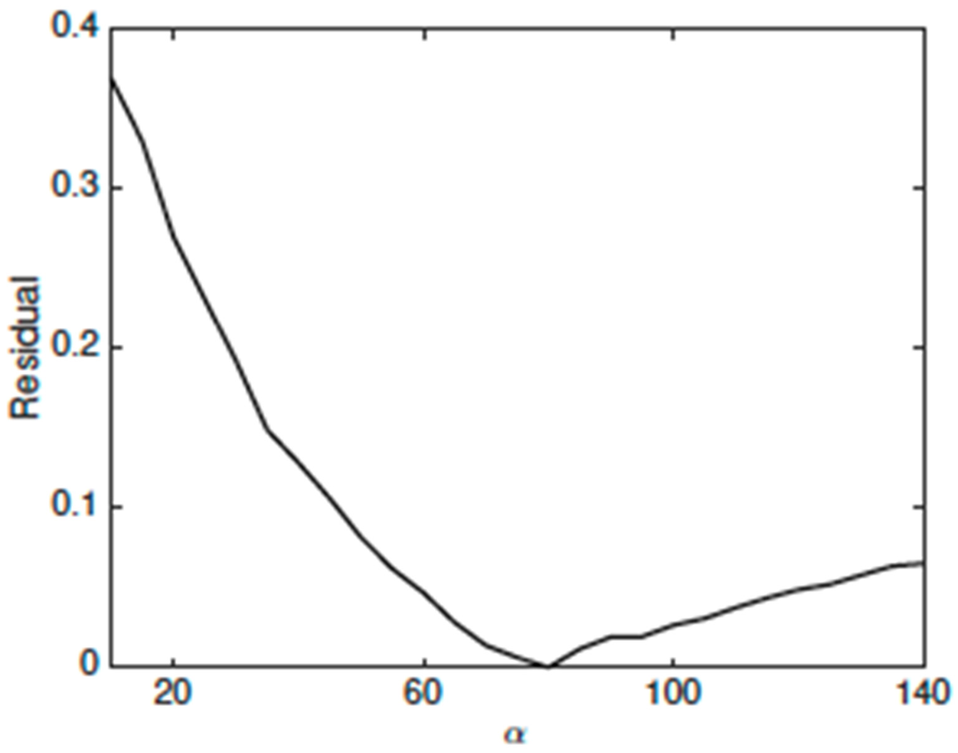
where we have approximated R L / 2 in Equation (3). We used a quartic phase-mask given by Equation (7) with n = 4 and with a strength value α determined via the optimization procedure described in Section 2.4. To this end a bounded global-minimum search (using the MATLAB fminbnd function) was used to find the α value that gave the minimum residual to Equation (12) with β = 0.6 . The advantage of this approach is that the best trade-off between extending the DOF and preserving image quality is automatically found, and no empirical selection of α is needed. In essence, the algorithm seeks the best solution to Equation (12) for α in the positive range of values. In practice, a test with the optical setup parameters of our study showed that Equation (12) is a well-behaved function of α (Figure 2), with a single minimum α value within the range from 10 to 50. We obtained the optimal value α = 31.9 . Since α represents the maximum optical path difference of the APM, it is typically expressed in terms of either modulo- π or wavelength units. For this reason, we use the equivalence α = 31.9 = 100 / π hereafter. Figure 3 illustrates (except for the circular pupil mask) the grey-level representation of the phase distribution of the combined system of APM + FL with the appropriate α = 100 / π .
Figure 4 shows the horizontal PSF profiles of the combined system with α = { 0 ,   100 / π ,   300 / π   } obtained for a distant point-source through numerical simulations using a Fourier optics approach [14]. Note that for α = 0 in Equation (7), the generalized pupil function is just the physical aperture and, therefore, this case corresponds to the diffraction-limited system. The image planes range from z = 400   mm to z = 600   mm in steps of 50   mm in Figure 4.
In all cases ( α = { 0 ,   100 / π ,   300 / π   } ), the best and most compact PSF is obtained at or near the in-focus plane ( z 0 = 500   mm ) (central frame in Figure 4) according to the design focal distance f = 500   mm . Apart from the asymmetric lateral tail at the different z -image planes of the combined systems with α = { 100 / π ,   300 / π   } (second and third row in Figure 4), the PSF shape is nearly invariant, with defocus over a wider range of z - positions than that of the diffraction-limited system ( α = 0 , first row).
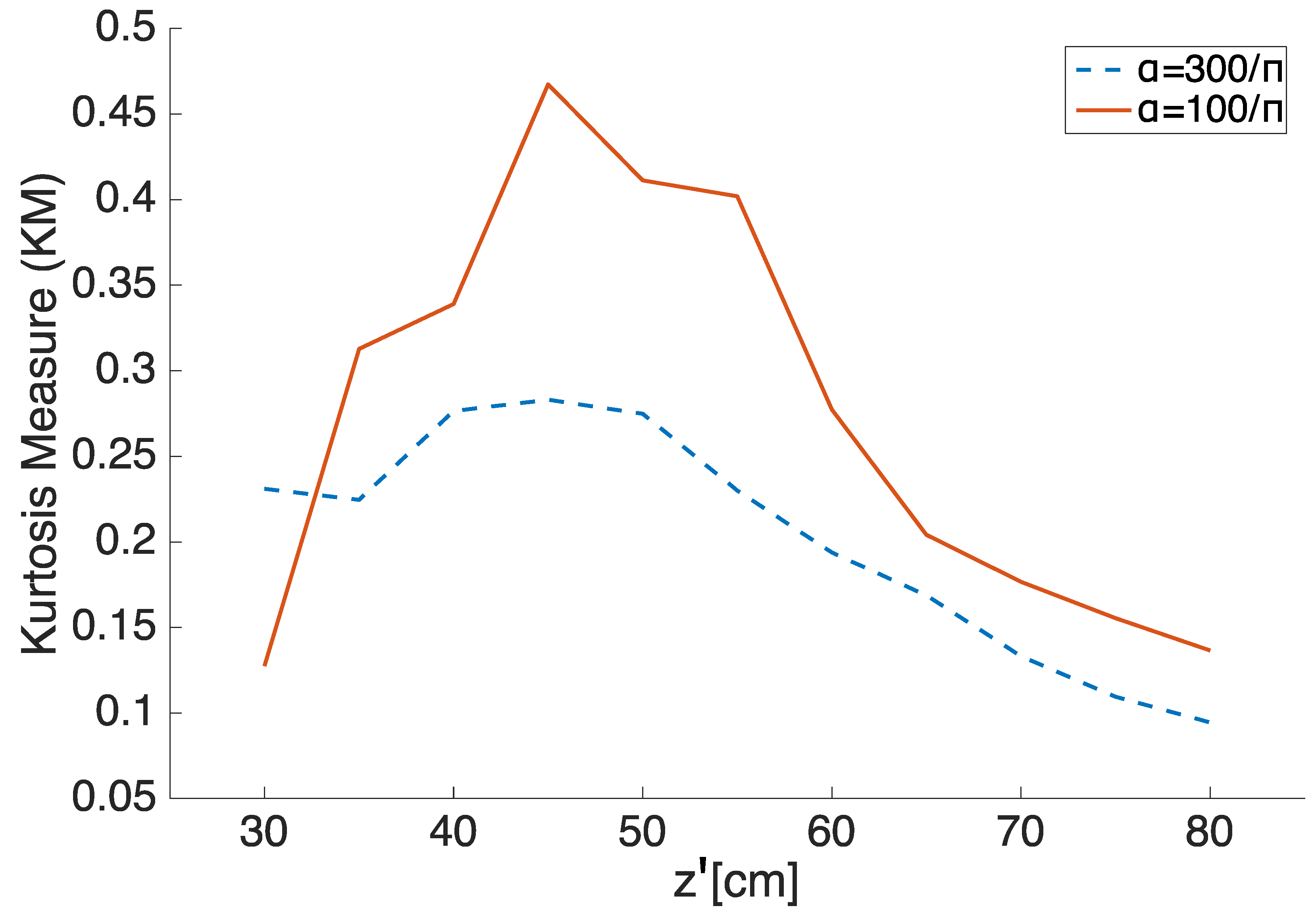
As expected, a system with a larger α = 300 / π (third row of Figure 4), exhibits greater invariance to defocus than the system with α = 100 / π (second row). However, the spread of the in-focus and the defocused PSFs obtained with α = 300 / π is considerably wider than that obtained with the optimized value α = 100 / π . This means that the system with α = 300 / π involves a more severe image degradation, with a significant decrease in quality with respect to the optimized case. This observation agrees with the results obtained with the KM metrics in Figure 5. The KM measures the kurtosis (spread) of the PSFs obtained with the combined system for a given α , relative to the one obtained with a diffraction-limited system. From Figure 5, the system with the optimized value α = 100 / π reaches higher KM values in the vast extension of the considered z -image planes than the system with α = 300 / π , except for the extreme z = 300   mm . Moreover, the optimal system shows a KM peak near the in-focus z 0 = 500   mm position which would be the ideal performance for an ophthalmic lens design that would benefit, for instance, far vision.
Finally, the system with the optimized α value represents the trade-off solution between extending the DOF (large invariance to defocus) and maintaining the maximum fidelity in image formation, this involving expectance of acceptable degradation. Figure 6 illustrates these results through the numerical simulation of the PSFs and the image of an extended object (character 2) within the range of z -image planes. Image magnification was taken into account by scaling properly according to geometrical optics imaging in the z -image plane range [21]. The best image of both the point-source and the extended object is clearly near the in-focus position z 0 = 500   mm (central frame in Figure 6); however, even at the extremes of the z -image plane range z = { 300 ,   800 }   mm , character 2 is discernible despite a mild blur. Note that the PSF shows less spread in directions other than the main x and y axes (horizontal and vertical) and, therefore, the image degradation in those angular directions would be lower.

3.2. Experimental Results on Optical Bench

We dealt with the phase distribution of the combined system APM + FL (Figure 3c) as a programmable DOE; we displayed it on a parallel-aligned liquid-crystal on silicon (LCoS) SLM working by reflection in a phase-only modulation regime (Figure 1) [3,10]. The Holoeye-HEO LCoS SLM used to display the DOEs in our experiment had been previously characterized for a linear and optimized performance following the procedure reported in [22]. The SLM had a resolution of 1920 × 1080 pixels in a 15.36 mm × 8.64 mm array. The combined APM + FL system was displayed using a square array of 1080 × 1080 pixels. Other specifications were a pixel pitch equal to 8 microns, 87% fill factor, and (8-bit) 256 electrically addressable gray levels.
A linearly polarized He-Ne laser beam with λ = 632.8   nm was used for illumination (element 1 in Figure 1), and a half-wave plate (element 3) to adjust the polarization plane of the incident beam on the SLM, to obtain a phase-only modulation according to the previous characterization of the device [22]. The beam was spatially filtered by a small pinhole (element 4) placed on the optical axis, and then collimated by a lens (element 7, with f a u x = 200   mm ), to represent a point-source at infinity. Alternatively, we used character 2 from the USAF test (element 6) and the same collimator for an extended object at infinity that covered an angular field of 0.07 4.2 . To obtain incoherent illumination a ground-glass rotating diffuser (element 5) was located against the extended object. The object (either the point-source or character 2) was imaged by the DOE displayed on the LCoS SLM. A CCD sensor (element 11) acquired the image intensity. We fixed the capturing parameters of the CCD camera (PCO 1600, with large 16-bit dynamic range) so as to avoid saturation. The CCD camera was mounted on a separate bench for linear translation to cover the considered z -image plane range. Further details about the setup (Figure 1) can be found elsewhere [10].
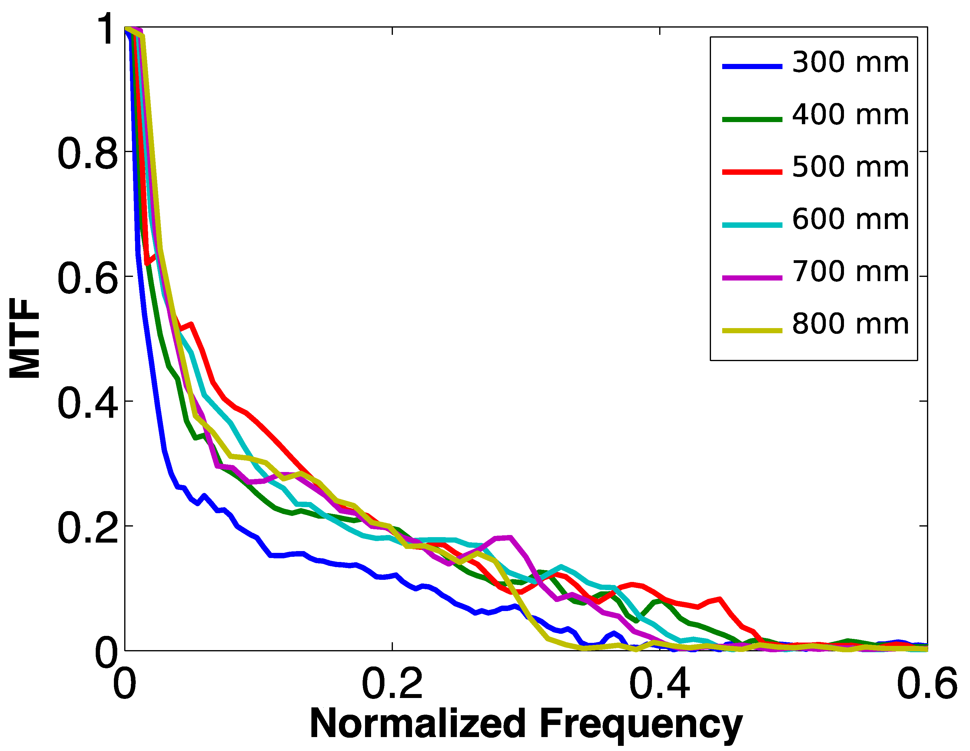
The experimental results obtained for the combined APM + FL system, with the optimized value α = 100 / π , are shown in Figure 7. Note that there is an excellent agreement with the images obtained by numerical simulation (Figure 6). Figure 8 contains the MTFs obtained in the optical experiment. We used a standard procedure based on the measurement of the edge-spread function to calculate the one-dimensional MTF profiles of Figure 8 [16,23]. All MTFs are very close, which confirms the EDOF property, except for the extreme z = 300   mm , which was the one with the largest defocus value ( W 20 = 19.7 λ ). Overall, the system performs very well, with no contrast inversions. As expected, the MTF for the design focal length z 0 = 500   mm (red line in Figure 8) is slightly better than the rest. From the simulated and experimental PSF results, we remark an excellent property: its shape, orientation, and on-axis position remain constant through the z -image plane segment, only modified by the natural magnification. This constancy of performance does not occur with other elements that have already been proposed for focus extension in ophthalmic optics such as, for instance, the light sword [9,24,25].

3.3. Exemplary Case: Optimized EDOF IOL

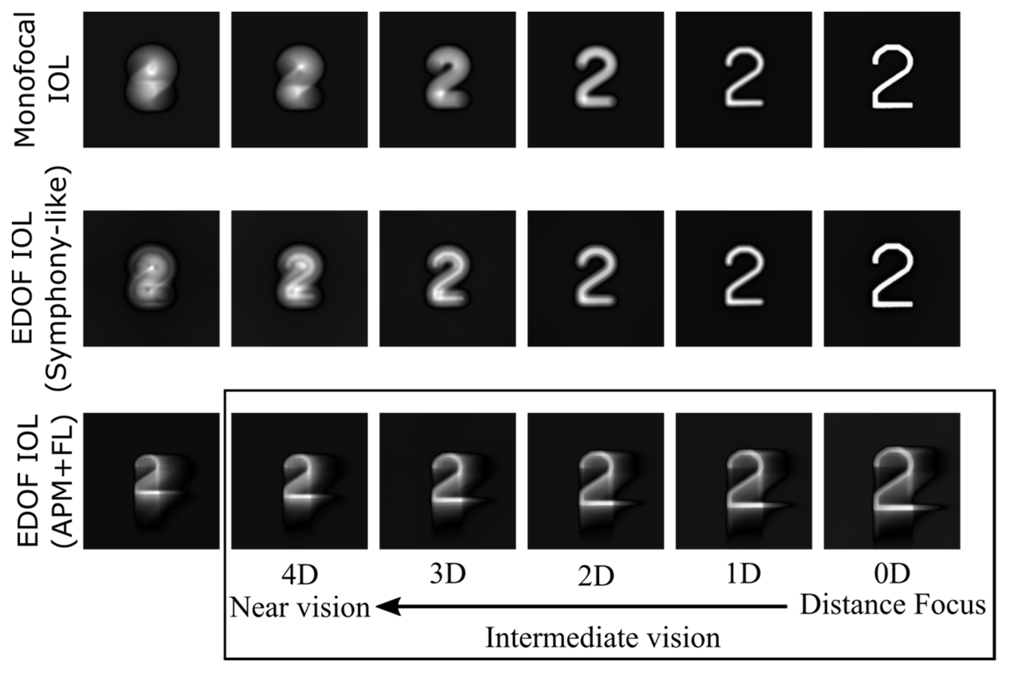
As an exemplary case of application to ophthalmic lenses, we consider the design of an EDOF IOL. Let us assume that the lens, with a refractive power 20 D ( f = 50   mm ) and pupil diameter d = 6   mm , is immersed in a wet-cell assembly filled with a liquid of refractive index n = 1.336 , which corresponds approximately to the ocular humors. For the purpose of optimization, we take an axial segment of ± 8.3   mm around the design focal plane intended for far vision, which is located at z 0 = f = 50   mm from the lens (Figure 9). This axial segment in the image space is equivalent to z 0 = { 41.7 58.3 } mm that, in terms of defocus coefficients, corresponds to W 20 = { 37.9 27.1 } λ (we kept λ = 632   nm for the sake of simplicity and comparison with the experiment before, although the design wavelength of IOLs corresponds to a green light, as fixed by the ISO standard to 546 nm [26]) and, in terms of vergences, to P = { + 5.3 3.8 } D . Certainly, a design axial segment providing such a P power variation covers, by far, the need for focus extension in normal emmetropic vision, which would range from 0.0 to 4.0 D at the IOL plane; the latter is the additional power needed to image a near object placed at about 0.3 m from the observer (that is, about a 3 D add-power at the spectacle plane). Despite this fact, we have chosen a longer segment to ensure the best image quality for far vision at the design focus ( z 0 = f = 50   mm )—which involves taking advantage of only half of the segment length—and yet to have enough focus extension in the positive defocus range to discard the extreme. We recall that such an extreme corresponds to the image plane position with the maximum W 20 value and, therefore, to the worst performance condition as evidenced in Figure 8 (graph for z = 300   mm ). With these design parameters and constraints in mind, we applied the optimization procedure described in Section 2 to obtain the value of the strength factor for the combination of APM + FL that represents the IOL. The trade-off value that minimized the residual (Equation (12)) was α = 80 251 / π (Figure 10). Figure 11 shows the horizontal PSFs and Figure 12 the image of the extended object for the optimized IOL imaging system in the axial segment corresponding to z 0 = { 41.7 50.0 } mm , equivalent to P = { + 5.3 0.0 } D . For the sake of comparison, Figure 12 includes the images obtained, in the same defocus range, by a real EDOF IOL (3.5 mm pupil) and a conventional monofocal IOL (6.0 mm pupil) of the same design focal length f = 50   mm . For the real EDOF IOL design, we have assumed the description found in [27] as corresponding to the commercial TECNIS Symfony® IOL (Johnson & Johnson). In our computational comparison, the Symfony-like design consisted of a pupil-dependent diffractive bifocal lens of nominal +1.75 D add-power at the IOL plane (+1.98 D measured for λ = 625 ± 10   nm ) intended for intermediate vision. For the calculation, we considered the energy efficiency ratio reported for the distance/intermediate foci, i.e., 5.68 for a pupil size of 3.5 mm [27]. Due to apodization, the Symfony-like design for larger apertures would benefit the distance focus, and hence, higher efficiency ratios would be expected.
Note that, for the optimized APM + FL combination (6.0 mm pupil), the PSFs are very similar through the defocus range in Figure 11; the same can be said for character 2′s images in Figure 12, except for the extreme on the left, which would eventually be discarded for a more useful range of vision of 4 D at the IOL plane (marked with a rectangle in Figure 11 and Figure 12). As expected, the monofocal IOL (6.0 mm pupil) achieves the best image with far-vision focus, but the image quality decreases rapidly for mid- to near-vision distances. Such a quality decrease is slower with the EDOF Symfony-like IOL in Figure 12, in part because of its optical design and in part because of the smaller pupil (3.5 mm). At the intermediate vision distance (2D), the in-focus image formed by the intermediate focus of the Symfony-like IOL (+1.98 D for λ = 625 ± 10   nm ) appears overlaid by a slightly larger out-of-focus image formed by the distance focus. The image degradation worsens progressively in the 3D and 4D positions. In contrast, the proposed optimized APM + FL (6.0 mm pupil) sufficiently resolves the image shape with nearly constant degradation throughout the whole 4D range of vision at the IOL plane (meaning from an infinite distance to ~ 0.3   m from the observer). This result has been presented here only as an example, to illustrate the method performance and its potential. We think it could be further improved by adjusting the axial segment that determines the useful range of vision and the pupil size in the optimization process. In fact, the target range of vision has followed different trends over time. Early bifocal IOLs of 4 D add-power were later modified to 3 D. This bifocal design provided relatively good vision for far and near objects, corresponding to two distinct foci, but the patients reported visual disturbances (e.g., halo, glare) and poor visual quality for intermediate distances. The current notion of an EDOF IOL does not really provide good near vision, but keeps good distance vision that extends into the intermediate region. Actual EDOF IOLs have a modest focal improvement (1 D extension of focus, or even 0.5 D [28], may potentially be useful). Concerning the pupil, although the IOL optical aperture is 6 mm, the central 3 mm or 3.5 mm diameter aperture draws most of the attention, because that is an average illumination diameter at the IOL plane for an older eye. These moderate constraints of the focus extension and pupil size should facilitate the optimization of an IOL based on an APM + FL design.

4. Conclusions

We have shown that the asymmetric quartic phase-mask can be a suitable element for extending the depth of focus of a simple monofocal lens with applications in ophthalmic optics. Using the proposed optimization algorithm, we have obtained a remarkable axial extension in the image space with a minimized spread of the PSF. We have validated the proposal through numerical simulation and on-bench optical experimentation. Although the numerical and optical experiments considered a programmable modulo- 2 π diffractive optical element for displaying the optimized combination APM + FL on a phase-only SLM, there is no need for manufacturing a pure diffractive profile. Instead, a continuous, smoothly varying curvature would be implemented—for instance, by means of freeform surface lathing, molding injection or embossing, among other methods—for lens prototyping. Therefore, the combination of the asymmetric mask and the lens can be implemented in a single optical element. This property is relevant because a refractive element overcomes the typically strong spectral dependence of DOEs when operating under broadband illumination.
From the proof-of-concept results, we consider that the application of the proposed optical element to ophthalmic optics is feasible, in particular, for the design of an EDOF IOL. Despite the fact that the optimization process does not fully suppress the lateral tails of the PSF peak, it ensures their reduction to a minimum extent while keeping a nearly constant degradation: the PSF shape, orientation, and on-axis position remain constant for the image plane positions covered by the design axial segment, and are only modified by the natural magnification change. These properties can be advantageous in comparison to other asymmetric EDOF designs that have already been proposed for presbyopia correction. Since they are static optical elements, the issue of image degradation will be always present, and particularly bothersome just after lens implantation. Although the human visual system does not allow further digital processing to restore the retinal image, the brain has a powerful resource—neural adaptation—that provides neural compensation for the eye’s optical aberrations [6]. This capability depends on a variety of factors, including the personal characteristics of the subject. The constancy of the degradation over the observation distance would likely alleviate the challenge for achieving an acceptable level of aberration in a short time frame for adaptation.

Author Contributions

Conceptualization, L.A.R., A.G.M. and M.S.M.; methodology, L.A.R., A.G.M. and M.S.M.; software, A.G.M.; experiment, L.A.R.; validation, A.G.M., and M.S.M.; formal analysis, A.G.M. and M.S.M.; investigation, L.A.R., A.G.M. and M.S.M.; resources, M.S.M.; data curation, L.A.R. and A.G.M.; writing—original draft preparation, L.A.R. and A.G.M.; writing—review and editing, A.G.M. and M.S.M.; visualization, L.A.R. and A.G.M.; supervision, M.S.M.; project administration, M.S.M.; funding acquisition, M.S.M. All authors have read and agreed to the published version of the manuscript.

Funding

Funding for this project was provided by the following: Agencia Estatal de Investigación (Spanish government) and European social fund, (PID2020-114582RB-I00/AEI/10.13039/501100011033); Centre de Cooperació i Desenvolupament, Universitat Politècnica de Catalunya-BarcelonaTech (Spain), Project B004-2019; Ministerio de Ciencia, Tecnología e Innovación (Colombia), Project 124489786239 (Contract 763-2021).

Institutional Review Board Statement

Not applicable.

Informed Consent Statement

Not applicable.

Data Availability Statement

All data generated or analyzed during this study are included in this published article. The datasets generated during and/or analyzed during the current study are available from the corresponding author on reasonable request.

Conflicts of Interest

The authors have no conflict of interest to disclose.

References

  1. Wang, B.; Ciureda, K.J. Depth-of-Focus of the Human Eye: Theory and Clinical Implications. Surv. Ophthalmol. 2006, 51, 75–85. [Google Scholar] [CrossRef] [PubMed]
  2. Zalevsky, Z. Extended depth of focus imaging: A review. SPIE Rev. 2010, 1, 018001. [Google Scholar] [CrossRef] [Green Version]
  3. Romero, L.A.; Millan, M.S. Programmable Diffractive Optical Elements with Applicability in Ophthalmic Optics. Opt. Pura Apl. 2017, 50, 75–91. [Google Scholar] [CrossRef]
  4. Castro, A.; Ojeda-Castañeda, J. Asymmetric phase masks for extended depth of field. Appl. Opt. 2004, 43, 3474–3479. [Google Scholar] [CrossRef]
  5. Castro, A.; Frauel, Y.; Javidi, B. Integral imaging with large depth of field using an asymmetric phase mask. Opt. Express 2007, 15, 10266–10273. [Google Scholar] [CrossRef]
  6. Artal, P.; Chen, L.; Fernández, E.J.; Singer, B.; Manzanera, S.; Williams, D.R. Neural compensation for the eye’s optical aberrations. J. Vis. 2004, 4, 281–287. [Google Scholar] [CrossRef]
  7. Sawides, L.; de Gracia, P.; Dorronsoro, C.; Webster, M.A.; Marcos, S. Vision is adapted to the natural level of blur present in the retinal image. PLoS ONE 2011, 6, e27031. [Google Scholar] [CrossRef] [Green Version]
  8. Radhakrishnan, A.; Dorronsoro, C.; Sawides, L.; Webster, M.A.; Marcos, S. A cyclopean neural mechanism compensating for optical differences between the eyes. Curr. Biol. 2015, 25, 188–189. [Google Scholar] [CrossRef] [Green Version]
  9. Petelczyc, K.; Bara, S.; Ciro López, A.; Jaroszewicz, Z.; Kakarenko, K.; Kołodziejczyk, A.; Sypek, M. Contrast transfer characteristics of the light sword optical element designed for presbyopia compensations. J. Eur. Opt. Soc. Rapid Publ. 2011, 6, 11053. [Google Scholar] [CrossRef] [Green Version]
  10. Romero, L.A.; Millan, M.S.; Jaroszewicz, Z.; Kolodziejczyk, A. Double peacock eye optical element for extended focal depth imaging with ophthalmic applications. J. Biomed. Opt. 2012, 17, 046013. [Google Scholar] [CrossRef] [Green Version]
  11. Charman, W.N.; Liu, Y.; Atchison, D.A. Small-aperture optics for the presbyope: Do comparable designs of corneal inlays and intraocular lenses provide similar transmittances to the retina? J. Opt. Soc. Am. A 2019, 36, B7–B14. [Google Scholar] [CrossRef] [PubMed]
  12. Benard, Y.; Lopez-Gil, N.; Legras, R. Subjective depth of field in presence of 4th-order and 6th-order Zernike spherical aberration using adaptive optics technology. J. Cataract Refract. Surg. 2010, 36, 2129–2138. [Google Scholar] [CrossRef] [PubMed]
  13. Barbero, S. Smooth multifocal wavefronts with a prescribed mean curvature for visual optics applications. Appl. Opt. 2021, 60, 6147–6154. [Google Scholar] [CrossRef] [PubMed]
  14. Goodman, J.W. Introduction to Fourier Optics, 2nd ed.; McGraw-Hill: New York, NY, USA, 1996; Chapter 5. [Google Scholar]
  15. Hopkins, H.H. The frequency response of a defocused optical system. Proc. R. Soc. London Ser. A Math. Phys. Sci. 1955, 231, 91–103. [Google Scholar]
  16. Boreman, G.D. Modulation Transfer Function in Optical and Electro-Optical Systems, Volume TT 52; SPIE Press: Bellingham, DC, USA, 2001. [Google Scholar]
  17. Marsack, J.D.; Thibos, L.N.; Applegate, R.A. Metrics of optical quality derived from wave aberrations predict visual performance. J. Vis. 2004, 4, 8. [Google Scholar] [CrossRef]
  18. Thibos, L.N.; Hong, X.; Bradley, A.; Applegate, R.A. Accuracy and precision of objective refraction from wavefront aberrations. J. Vis. 2004, 4, 329–351. [Google Scholar] [CrossRef] [Green Version]
  19. Demenikov, M. Optimization of hybrid imaging systems based on maximization of kurtosis of the restored point spread function. Opt. Lett. 2011, 36, 4740–4742. [Google Scholar] [CrossRef]
  20. Carles, G.; Carnicer, A.; Bosch, S. Phase mask selection in wavefront coding systems: A design approach. Opt. Laser Eng. 2010, 48, 779–785. [Google Scholar] [CrossRef]
  21. Voelz, D.G. Computational Fourier Optics: A MATLAB Tutorial; SPIE Press: Bellingham, DC, USA, 2011; Chapter 7. [Google Scholar]
  22. Otón, J.; Ambs, P.; Millán, M.S.; Pérez-Cabré, E. Multipoint phase calibration for improved compensation of inherent wavefront distortion in parallel aligned liquid crystal on silicon displays. Appl. Opt. 2007, 46, 5667–5679. [Google Scholar] [CrossRef]
  23. Samei, E.; Flynn, M.; Reimann, D. A method for measuring the presampled MTF of digital radiographic systems using an edge test device. Med. Phys. 1998, 25, 102–113. [Google Scholar] [CrossRef] [Green Version]
  24. Mikuła, G.; Kolodziejczyk, A.; Makowski, M.; Prokopowicz, C.; Sypek, M. Diffractive elements for imaging with extended depth of focus. Opt. Eng. 2005, 44, 058001. [Google Scholar] [CrossRef]
  25. Romero, L. Programmable Diffractive Optical Elements with Applicability in Ophthalmic Optics. Ph.D. Dissertation, Universitat Politècnica de Catalunya-BarcelonaTech, Barcelona, Spain, 2013. [Google Scholar]
  26. ISO 11979-2; Ophthalmic Implants, Intraocular Lenses—Part 2: Optical Properties and Test Methods. International Organization for Standardization: Geneva, Switzerland, 2014.
  27. Millán, M.S.; Vega, F. Extended depth of focus intraocular lens: Chromatic performance. Biomed. Opt. Express 2017, 8, 4294–4309. [Google Scholar] [CrossRef] [PubMed] [Green Version]
  28. ANSI Z80.35-2018; American National Standard Institute, Ophthalmics. Extended Depth of Focus Intraocular Lenses. The Vision Council: Alexandria, VA, USA, 2018.
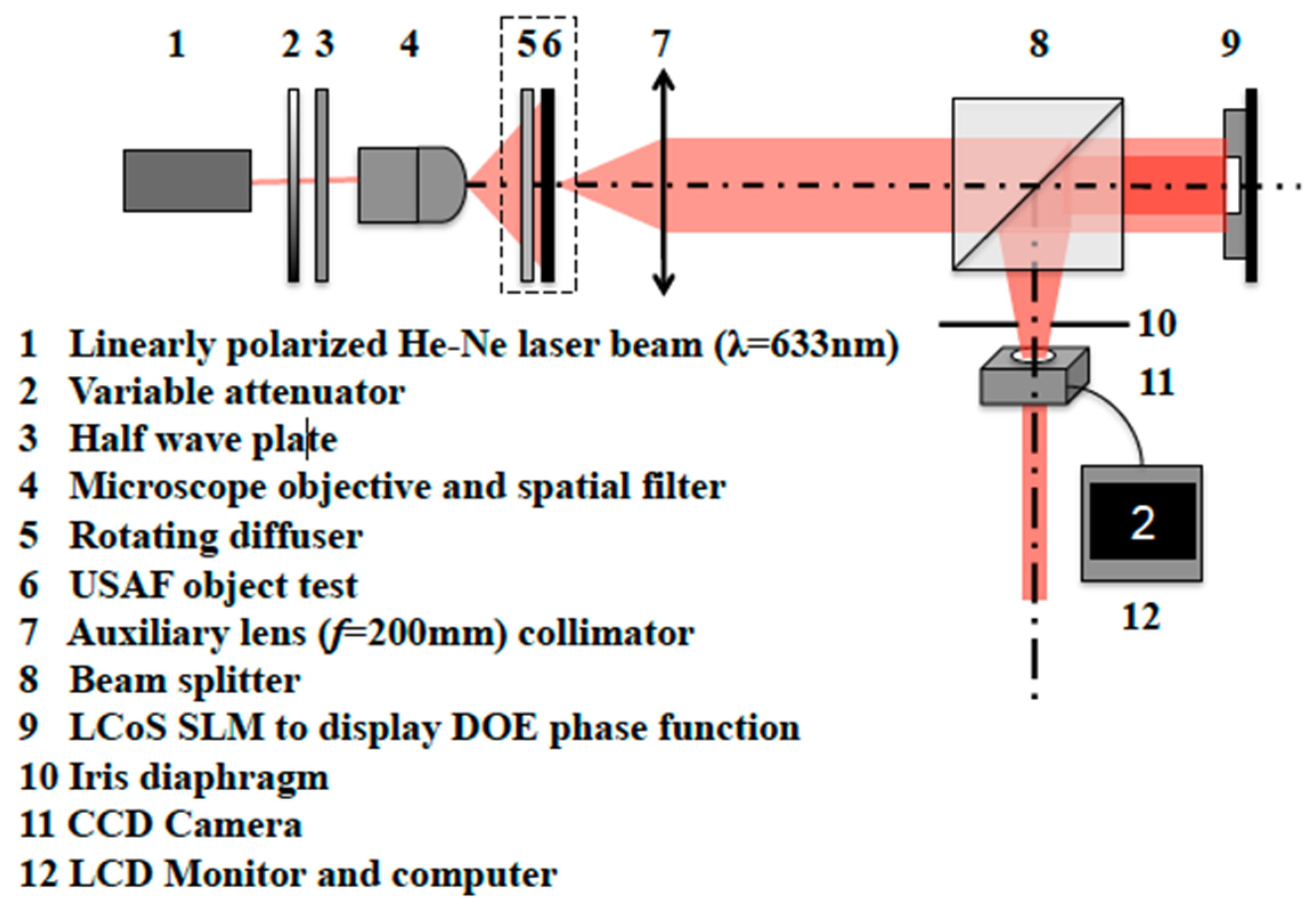
Figure 1. Experimental setup to evaluate the EDOF DOE displayed on the phase-only SLM (element 9). Element 5 is introduced for incoherent illumination. Element 6 is the large-object test from which character 2 (the one that identifies group 2 in the 1951 USAF resolution test chart) is taken for the image-forming experiments. To obtain the PSF, elements 5 and 6 were removed, and element 4 (microscope objective and spatial filter) was moved forward to reach the front focal plane of the collimator (element 7). This way, the image intensity of the point-source at infinity was registered with the CCD sensor (element 11). The iris diaphragm (element 10) limited the square aperture of the SLM to a circular pupil.
Photonics 09 00119 g001
Figure 2. Example of optimization: Residual (Equation (12)) versus α . The solution is determined by the α value that minimizes the residual, which in this example, occurs for α = 31.9 = 100 / π .
Photonics 09 00119 g002
Figure 3. Grey level modulo- 2 π phase distributions of the combined APM + FL system. (a) APM with n = 4 and optimal α = 31.9 = 100 / π ; (b) FL with focal length f = 500   mm ; (c) sum of the APM and FL phases.
Photonics 09 00119 g003
Figure 4. Horizontal PSF profiles of the combined APM + FL imaging system with α = { 0 ,   100 / π ,   300 / π   } in different z -image positions (the central rectangle highlights those in the in-focus position). Results obtained by numerical simulation.
Photonics 09 00119 g004
Figure 5. Kurtosis measure of the PSFs of the combined APM + FL imaging system along the z′-image plane range.
Photonics 09 00119 g005
Figure 6. Numerical simulation of the PSFs (top) and the images of the extended object (bottom) for the combined APM + FL imaging system with the optimized value α = 100 / π along the z’-image plane range (rectangle in the in-focus position). The pupil size was L = 8.64 mm.
Photonics 09 00119 g006
Figure 7. Experimental results of the PSFs (top) and the images of the extended object (bottom) for the combined APM + FL imaging system with the optimized value α = 100 / π along the z’-image plane range (rectangle in the in-focus position) obtained with the optical setup depicted in Figure 1. The pupil size was L = 8.64 mm.
Photonics 09 00119 g007
Figure 8. MTFs computed, in the horizontal direction, from the experimental measurement of the edge-spread function obtained optically in each z position.
Photonics 09 00119 g008
Figure 9. Exemplary case of application: EDOF IOL.
Photonics 09 00119 g009
Figure 10. Optimization in the exemplary case of an EDOF IOL consisting of a combination APM + FL. The value that minimizes the residual (Equation (12)) is for α = 80 251 / π .
Photonics 09 00119 g010
Figure 11. Horizontal PSFs of the combined APM + FL with α = 80 = 251 / π , intended for an EDOF IOL, in different z -image positions. The rectangle highlights the useful range of vision at the IOL plane.
Photonics 09 00119 g011
Figure 12. Images of an extended object of a monofocal IOL (top), an EDOF (Symfony-like) IOL (center), and a combined APM + FL with α = 80 = 251 / π , intended for an EDOF IOL (bottom), in different z -image positions. The rectangle highlights those in the useful range of vision at the IOL plane. Results obtained by numerical simulation.
Photonics 09 00119 g012
Publisher’s Note: MDPI stays neutral with regard to jurisdictional claims in published maps and institutional affiliations.