Article

An Optimal Scheme for the Number of Mirrors in Vehicular Visible Light Communication via Mirror Array-Based Intelligent Reflecting Surfaces

1
Guangxi Key Laboratory of Wireless Wideband Communication and Signal Processing, Guilin University of Electronic Technology, Guilin 541004, China
2
School of Information and Communication, Guilin University of Electronic Technology, Guilin 541004, China
3
School of Computer Science and Information Security, Guilin University of Electronic Technology, Guilin 541004, China
4
College of Electronic and Information Engineering, Beibu Gulf University, Qinzhou 535011, China
*
Author to whom correspondence should be addressed.
Photonics 2022, 9(3), 129; https://doi.org/10.3390/photonics9030129
Submission received: 25 January 2022 / Revised: 16 February 2022 / Accepted: 23 February 2022 / Published: 24 February 2022
(This article belongs to the Special Issue Visible Light Communication (VLC))

Abstract

:
The optimization problem of the number of mirrors under energy efficiency (EE) maximization for vehicular visible light communication (VVLC) via mirror array-based intelligent reflecting surface (IRS) is investigated. Under considering that the formulated optimization problem is subject to the real and non-negative of the transmitted signal, the maximum power consumption satisfied luminous ability and eye safety, the minimum achievable rate, and the required bit error ratio (BER), EE is proved to be a unimodal function of the number of mirrors. Then, the binary search-conditional iteration (BSCI) algorithm is proposed for quickly finding the optimal number of mirrors with maximum EE. Numerical results demonstrate that fewer mirrors can obtain the maximum EE, and the computational complexity of the BSCI algorithm is reduced by 10 5 orders of magnitude, compared with the Bubble Sort method.

1. Introduction

Reliable information transmission between vehicles is essential [1,2,3] in the intelligent transportation system (ITS). Vehicle-to-vehicle (V2V) communication mainly adopts radio frequency (RF) communications currently [4,5,6,7]. RF communications are prone to problems, such as lack of spectrum resources, electromagnetic interference, and synchronization limitations when the traffic flow is large and the vehicles are very dense, which brings enormous challenges to reliable V2V communication.
In the visible light communication (VLC) system, the information is sent by the LEDs’ high-speed flashing and transmitted through the channel to the receiver [8,9,10], such as a Photo-Diode (PD) [11], image sensor [12], or high-speed camera [13]. The received optical signal is converted into the electrical signal through photoelectric conversion firstly; then after signal processing, the original information is restored. It can realize the communication while satisfying the luminous ability, which can be used as a technology complementing the RF communications and improve the efficiency of resources, which has the characteristics of rich spectrum resources, high energy efficiency, and greenness.
With the continuous progress of semiconductor technology, LED gradually replaces the traditional light source and becomes an important choice for lamps [14,15,16], which provides a hardware basis for realizing VLC. When the vehicle is driving on the road, the headlamps or taillights between the front and rear vehicles can be used as the transmitter, and the receiver can be installed on another vehicle, and the light emitted by the LED can reach the receiver directly through the line-of-sight (LOS) link [17,18,19,20]. For VLC with the non-line-of-sight (NLOS) link, the road surface can be used as the reflector [21]. The light emitted by the headlamp reaches the road surface firstly and then reaches the receiver through the reflection of the road surface. In this case, the receiver is in the front and the transmitter is in the back, and a certain distance should be maintained to ensure that the reflected light is within the field of view (FOV) of the receiver.
When the headlamps or taillights are used as transmitters, the light emitted by the transmitters cannot reach the receivers which are installed on other vehicles for parallel. According to the propagation characteristics of optics, it also cannot be reached by road reflection. The auxiliary means need to be considered to realize VLC between parallel vehicles.
The intelligent reflecting surface (IRS) [22,23] is a tunable metasurface composed of many low-cost passive reflective elements, which can manipulate the wavelength, polarization, and phase of the incident wave [24,25]. In the RF-based vehicular networks, the metasurfaces can revise the Snell’s law that redirecting the radio waves in the desired direction, which solves the problem that the communication is obstructed by strong obstacles and extends coverage in the highly dynamic vehicular environment [26], realizing keyless, secure transmission [27].
In the optical wireless communication, beam steering [28], beam shaping [29], and improving the service level of the link [30] for coherent light using metasurface-based IRS have been studied. For incoherent light (such as visible light), AM Abdelhady et al. [31] install IRS on the wall which reflects the incident light to the receiver by intelligently controlling the phase gradient of each metasurface and the orientation of each mirror in the indoor environment and the results proved that the performance of the mirror array is better than that of the metasurface. For the VLC between parallel vehicles, the mirror array-based IRS can be installed on the transportation infrastructure, and the light from the transmitter is reflected into the receiver by controlling the rotation angle of each mirror, which solves the problem of realizing VLC for parallel vehicles. Compared with the hybrid VLC-WiFi [32], the hardware implementation is simple, and the disadvantages of RF communication are solved.
In wireless communications, EE is defined as the ratio of transmitted bits to energy consumption. It is usually expressed in bits per Joule (bits/J) [33,34,35]. The higher the EE, the less energy the system expends for the same communication performance. It mainly contains two elements that are achievable rate and power consumption.
  • To ensure the effectiveness of the communication system, the achievable rate needs to reach a certain value. Since the transmitted signal is non-negative, real, and limited amplitude, the classical Shannon capacity formula is not suitable for VLC. Researchers have been studied the lower bound of the achievable capacity of the VLC system [36,37,38], and the achievable rate is proportional to the signal-to-noise ratio (SNR) [39]. Each mirror in the IRS is independently controlled, and the light reaches the receiver through their reflection. The total channel gain equals the sum of channel gain corresponding to each mirror, and the SNR becomes larger with the number of mirrors increasing.So, the achievable rate is not only related to the channel gain corresponding to each mirror, but also to the number of mirrors.
  • In the IRS-aided VLC system, the power consumption of the system is mainly included that of the transmitter, receiver, and IRS. The power consumption of the transmitter and receiver mainly includes signal power, DC offset, and the hardware static power consumption [40,41]. The power consumption of the IRS equals the sum of that for each mirror rotating. Therefore, the total power consumption changes depending on the number of mirrors.
Because the achievable rate and power consumption are related to the number of mirrors, the EE is also affected by the number of mirrors in the VLC system via mirror array-based IRS. To get the maximum EE, it is necessary to optimize the number of mirrors. Although the time allocation, power control, and phase matrix are analyzed for EE optimization [42], the influence of the number of mirrors in IRS on EE has not been analyzed, as far as the authors know.
The main contributions of this paper are as follows.
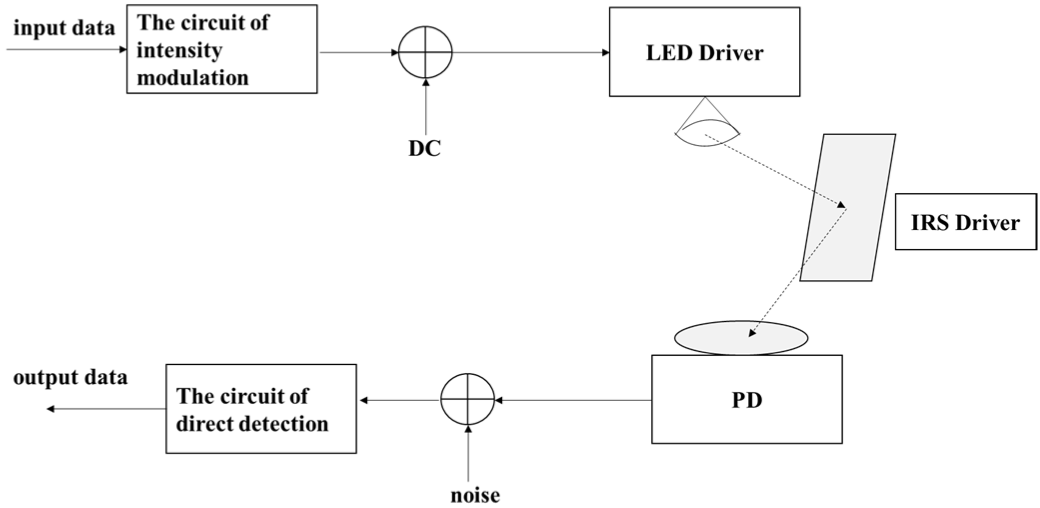
  • The VLC system via mirror array-based IRS for parallel vehicles is designed, which provides convenience for parallel vehicles to realize VLC. The right headlamp of the right vehicle is used as the transmitter, the receiver is installed between the two headlamps of the left vehicle, and the IRS is installed on the street light pole. The channel model of the system is analyzed, and the channel gain is calculated.
  • The calculation methods of the achievable rate and power consumption are given. According to the system model, the calculation formulas of the SNR and the instantaneous achievable rate are given. Based on reference [40], the total power consumption of the system and the power consumption of each mirror are analyzed. Both the achievable rate and the total power consumption are functions of the number of mirrors N, and thus EE is also a function of N.
  • The number of mirrors optimization problem under the EE maximization is formulated. Considering the non-negative of the transmitted signal, the maximum power consumption satisfied luminous ability and eye safety, the minimum achievable rate, and the required bit error rate (BER), the optimal value of N is found. According to the constraints and the properties of the achievable rate, EE is proved to be a unimodal function.
  • The binary search-conditional iterative (BSCI) algorithm is proposed to optimize N. According to the constraints of the optimization problem, the range of N is analyzed. The BSCI algorithm is proposed, which has low computational complexity and can quickly find the optimal value of N.
  • The optimization of N with different minimum achievable rates, noise power, and distance between vehicle and IRS is simulated. Firstly, the influence of the minimum achievable rate on the range of N is analyzed. Then, the optimal value of N is analyzed when the minimum achievable rate is constant and the noise power is different. Finally, the optimal value of N is analyzed when the distance between the vehicle and the IRS changes when the minimum achievable rate and noise power are constant. The theoretical analysis of this paper and the performance of the BSCI algorithm are proved.
Mathematical notations and definitions are presented in Table 1.
The remainder of this paper is organized as follows. In Section 2, the VLC system via mirror array-based IRS for parallel vehicles is designed, and the calculation methods of achievable rate and total power consumption are given. In Section 3, the optimization problem is formulated, and the range of N is analyzed according to the constraints. EE is proved to be a unimodal function, and the BSCI algorithm is proposed. The numerical results of the optimization of N with different minimum achievable rates, noise power, and distances between the vehicle and IRS are provided in Section 4. Finally, the conclusions and future research directions are drawn in Section 5.

2. System Model and Analysis

2.1. System Model

The considering scenario is that VLC via mirror array-based IRS for the parallel vehicles in adjacent lanes. The right headlamp (LED light source) of the right vehicle is used as the transmitter, and the PD is installed in the middle of the two headlamps of the left vehicle. The mirror array-based IRS is installed on the street light pole, and the height of the center point is consistent with the headlamps. Figure 1 shows the application scenario of the VLC system via mirror array-based IRS for parallel vehicles.
The model diagram of this scenario is given in Figure 2 for the convenience of analysis.
For the mirror array-based IRS, the rotation angle of each mirror in the IRS can be controlled independently without interfering with others. One of the mirrors is analyzed as an example. We define a Cartesian coordinate system whose origin is at the center of the mirror R i , j   ( 1 i n k ,   1 j n l ) . The position vector of the transmitter S can be expressed as
S = [ ( x s + w m 2 + ( j 1 ) ( w m + Δ w m ) ) y s ( z s + h m 2 + ( i 1 ) ( h m + Δ h m ) ) ] ,
The position vector of the PD can be expressed as
D = [ ( x d + w m 2 + ( j 1 ) ( w m + Δ w m ) ) y d h d ( z s + h m 2 + ( i 1 ) ( h m + Δ h m ) ) ] ,
To ensure that the reflected light reaches the receiver, each mirror must be rotated according to the position of the transmitter and receiver to obtain the appropriate angle. The mirror is first arranged via the clockwise rotation of the local z-axis with an angle β i , j and the local negative x-axis with an angle α i , j . The normal vector direction of the mirror after rotation is expressed as
N i , j ^ = R i , j S ^ + R i , j D ^ 2 + 2 R i , j S ^ T R i , j D ^ ,
where R i , j S ^ = S R i , j S R i , j 2 , R i , j D ^ = D R i , j D R i , j 2 , · 2 denote the 2 -norm, and ( · ) T denotes the transpose operator.
The relation between normal vector and rotation angle can be expressed as
N i , j ^ = [ sin ( β i , j ) cos ( α i , j ) cos ( β i , j ) cos ( α i , j ) sin ( α i , j ) ] .
In the actual scene, the distance of light transmission is much larger than the size of the light source, so it can be regarded as a point light source. The irradiance of the point light source after being reflected by the mirror R i , j to the PD can be expressed as [31]
E i , j = ρ ( m + 1 ) P i cos m ( θ R i , j S ) 2 π ( R i , j D 2 + R i , j S 2 ) 2 cos ( θ R i , j D ) ,
where E i , j represents the irradiance at the detector center contributed by the mirror R i , j . m is the order of Lambertian emission [43] related to the half-power semiangle of LED Φ 1 / 2 which can be expressed as m = l n 2 / l n ( cos Φ 1 / 2 ) .
According to Figure 2, cos ( θ R I , j S ) = e 2 T R i , j S ^ = e 2 T ( S R i , j ) / S R i , j 2 , cos ( θ R I , j D ) = e 2 T R i , j D ^ = e 2 T ( D R i , j ) / D R i , j 2 , and e 2 T = [ 0 , 1 , 0 ] .
According to the theory of VLC transmission [44], the direct current (DC) gain of the channel can be obtained as
H i , j I R S = ϖ T s ( θ R i , j D ) A d ρ ( m + 1 ) cos m ( θ R i , j S ) 2 π ( R i , j D 2 + R i , j S 2 ) 2 cos ( θ R i , j D ) g ( θ R i , j D ) ,
g ( θ R i , j D ) can be given as
g ( θ ) = { μ 2 s i n 2 ( ψ c ) 0 θ ψ c 0 θ > ψ c ,
The total DC gain can be obtained as
H I R S = i = 1 n k j = 1 n l H i , j I R S .

2.2. SNR

The transmitted signal of the LED can be expressed as
x = ζ s + I D C ,
where s is the input message.
The transmitted signal must be real and non-negative in VLC, and the optical power must be limited to human eye safety and illumination requirement. Generally, we assume that the signal s satisfies the following conditions:
A s A ,
E ( s ) = 0 ,
E ( s 2 ) = ε ,
A > 0 ,
ε > 0 ,
ζ s I D C ,
The total electrical power of the LED driver can be expressed as
E ( ( ζ s + I D C ) 2 ) = E ( ζ s 2 + 2 ζ s I D C + I D C 2 ) = ζ ε + I D C 2 ,
where P i = ζ ε is the power of the signal s .
The total electrical power should be limited, i.e.,
ζ ε + I D C 2 P m a x .
The received signal can be expressed as
y = η H I R S x + w ,
where w is the additive white Gaussian noise obeys a distribution N ( 0 , σ 2 ) with mean zero and variance σ 2 .
After removing the constant DC-offset, the SNR γ can be expressed as
γ = ( η H I R S ) 2 · P i σ 2 ,
The BER of the optical OOK modulation is given by
B E R = Q ( S N R ) ,
where
Q ( x ) = 1 2 π x e y 2 / 2 d y .  

2.3. The Achievable Rate

Because of the non-negative and real-valued amplitude, the classic Shannon capacity formula is not appropriate to VLC. In reference [36], a tight lower bound for dimmable VLC is proposed, so the achievable instantaneous rate can be expressed as
R = 1 2 B   log 2 ( 1 + e 2 π γ ) ,
where e is the value of the base of natural logarithms.
The Formula (8) can be rewritten as
H I R S ( N ) = n = 1 N H n .
where N is the total number of mirrors in the IRS. H n is the channel gain and arranged in decreasing order of magnitude. That is, H 1 = H m a x .
The Formula (17) can be rewritten as a function of N
R ( N ) = 1 2 B   log 2 ( 1 + e 2 π η 2 P i ( n = 1 N H n ) 2 σ 2 ) .
Assuming that the minimum achievable instantaneous rate of the VLC system is R m i n , that is
1 2 B   log 2 ( 1 + e 2 π γ ) R m i n ,
and
γ ( 2 2 R m i n B 1 ) 2 π e .
According to Formulas (14) and (21), we can obtain:
N H 1 n = 1 N H n ( 2 2 R m i n B 1 ) 2 π σ 2 e η 2 P i .
The minimum number of mirrors required to satisfy the in Equation (22) is
N ( 2 2 R m i n B 1 ) 2 π σ 2 e η 2 P i / H 1 .
According to the law of energy conservation, the received power is less than or equal to the transmitted power, we can get ( η H I R S ) 2 1 . So, it must hold η n = 1 N H n 1 .
Due to H n being arranged in decreasing order of magnitude, the sufficient condition η N H 1 1 can provide a simple upper-bound of the maximum number of mirrors, that is N 1 η H 1 .
When the IRS is installed on traffic infrastructures, its size must be limited in order not to obstruct traffic. When the size of each mirror is fixed, it is assumed that the maximum number of mirrors in the IRS is N m a x . So N m i n { N m a x , 1 η H 1 } .

2.4. The Total Power Consumption

In the VLC system via mirror array-based IRS, the total power consumption is composed of the transmit power, the hardware static power consumed in the transmitter and receiver, and IRS. The mirrors do not consume any transmit power since they are passive elements. The total power consumption model is shown in Figure 3.
In the system, the purpose of the mirror is to get a suitable position by rotation and reflect the emitted light to PD. Therefore, the hardware static power of the mirror array-based IRS is mainly used to control the rotation angle of mirrors. According to Formula (4), the rotation angle of the mirror is related to the normal vector. The normal vector depends on the distance between each mirror and the transmitter or receiver. Because the interval of mirrors is much smaller than the distance between mirrors and transmitter or receiver, the difference of mirrors rotation angle in IRS is relatively small. Therefore, the power consumption for each mirror rotation can be regarded as the same.
Based on the above considerations, the total power consumption of IRS-assisted VLC system can be expressed as
P t o t a l = P x + P h s p + N P m = ε + I D C 2 + P h s p + N P m ,  
where P h s p is the values of the hardware static power consumed in the transmitter and receiver. P m is the value of the power consumed in each mirror of IRS.
To analyze the influence of the number of mirrors on EE, the Formula (24) can be rewrit as
P t o t a l = N P m + P e l s e ,  
where
P e l s e = ε + I D C 2 + P h s p .

3. The Number of Mirrors Optimization

3.1. Problem Formulation

According to the definition of EE, it can be expressed as
E E ( N ) = R ( N ) P t o t a l = 1 2 B   log 2 ( 1 + e 2 π η 2 P i ( n = 1 N H n ) 2 σ 2 ) N P m + P e l s e .
Proposition 1.
Set   δ = e 2 π η 2 P i σ 2
, R ( N ) = 1 2 B   log 2 ( 1 + δ ( n = 1 N H n ) 2 ) . when δ ( n = 1 N H n ) 2 1 , R ( N + 1 ) R ( N ) R ( N + 2 ) R ( N + 1 ) .
Proof of Proposition 1.
R ( N + 1 ) R ( N ) = 1 2 B   log 2 ( 1 + δ ( n = 1 N + 1 H n ) 2 1 + δ ( n = 1 N H n ) 2 ) = 1 2 B   log 2 ( 1 + δ ( H N + 1 + n = 1 N H n ) 2 1 + δ ( n = 1 N H n ) 2 ) = 1 2 B   log 2 ( 1 + δ ( ( n = 1 N H n ) 2 + 2 ( H N + 1 n = 1 N H n ) + ( H N + 1 ) 2 ) 1 + δ ( n = 1 N H n ) 2 ) = 1 2 B   log 2 ( 1 + 2 δ ( H N + 1 n = 1 N H n ) 1 + δ ( n = 1 N H n ) 2 + δ ( H N + 1 ) 2 1 + δ ( n = 1 N H n ) 2 ) .
Similarly,
R ( N + 2 ) R ( N + 1 ) = 1 2 B   log 2 ( 1 + 2 δ ( H N + 2 n = 1 N + 1 H n ) 1 + δ ( n = 1 N + 1 H n ) 2 + δ ( H N + 2 ) 2 1 + δ ( n = 1 N + 1 H n ) 2 ) .
If R ( N + 1 ) R ( N ) R ( N + 2 ) R ( N + 1 ) , it holds that
1 2 B   log 2 ( 1 + 2 δ ( H N + 1 n = 1 N H n ) 1 + δ ( n = 1 N H n ) 2 + δ ( H N + 1 ) 2 1 + δ ( n = 1 N H n ) 2 ) 1 2 B   log 2 ( 1 + 2 δ ( H N + 2 n = 1 N + 1 H n ) 1 + δ ( n = 1 N + 1 H n ) 2 + δ ( H N + 2 ) 2 1 + δ ( n = 1 N + 1 H n ) 2 ) .
That is
2 ( H N + 1 n = 1 N H n ) 1 + δ ( n = 1 N H n ) 2 + ( H N + 1 ) 2 1 + δ ( n = 1 N H n ) 2 2 ( H N + 2 n = 1 N + 1 H n ) 1 + δ ( n = 1 N + 1 H n ) 2 + ( H N + 2 ) 2 1 + δ ( n = 1 N + 1 H n ) 2 .
Since H N + 1 H N + 2 and 1 + δ ( n = 1 N H n ) 2 1 + δ ( n = 1 N + 1 H n ) 2 , so
( H N + 1 ) 2 1 + δ ( n = 1 N H n ) 2 ( H N + 2 ) 2 1 + δ ( n = 1 N + 1 H n ) 2 .
Then, for (31) to hold, it is sufficient that
n = 1 N H n 1 + δ ( n = 1 N H n ) 2 n = 1 N + 1 H n 1 + δ ( n = 1 N + 1 H n ) 2 .
If we set t = n = 1 N H n , the inequality (33) can be written as an equivalent function
f ( t ) = t 1 + δ t 2 .
If f(t) is a monotonically decreasing function, then
d ( f ( t ) ) d t = 1 1 + δ t 2 2 δ t 2 ( 1 + δ t 2 ) 2 = 1 δ t 2 ( 1 + t 2 ) 2 0 .
So, when δ ( n = 1 N H n ) 2 1 , the inequality (33) can hold and R ( N + 1 ) R ( N ) R ( N + 2 ) R ( N + 1 ) . Hence the proof follows. □
Proposition 2.
E E ( N ) in (27) is a unimodal function.
Proof of Proposition 2.
Under the previously considered constraints of N, R ( N ) is an increasing function that grows more and more slowly. For the denominator in the Formula (27), P m P e l s e . N P m + P e l s e increases with increasing of N, and the growth rate becomes slower and slower.
For E E ( N ) , its changes are divided into two cases:
  • It keeps increasing with the increasing of N. The peak value of EE will not appear within the range of N;
  • There exists an N , E E ( N ) decreases monotonically when N N . At this time, E E ( N ) E E ( N + 1 ) E E ( N + 2 ) .
When E E ( N ) E E ( N + 1 ) , it holds
R ( N ) N P m + P e l s e R ( N + 1 ) ( N + 1 ) P m + P e l s e ,
and
N P e l s e P m + R ( N ) R ( N + 1 ) R ( N ) .
Since R ( N ) = ( R ( N + 1 ) R ( N ) ) + R ( N + 1 ) , (37) can be rewritten as
N P e l s e P m 1 + R ( N + 1 ) R ( N + 1 ) R ( N ) .
In Proposition 1, we proof that when δ ( n = 1 N H n ) 2 1 , R ( N + 1 ) R ( N ) R ( N + 2 ) R ( N + 1 ) .
So, the in Equation (38) implies
N P e l s e P m 1 + R ( N + 1 ) R ( N + 2 ) R ( N + 1 ) .
We have
R ( N + 1 ) ( N + 1 ) P m + P e l s e R ( N + 2 ) ( N + 2 ) P m + P e l s e .
It means that E E ( N + 1 ) E E ( N + 2 ) .
So, if E E ( N ) E E ( N + 1 ) , it can be proved that E E ( N ) E E ( N + 1 ) E E ( N + 2 ) E E ( N + 3 ) E E ( N + ) . To sum up, E E ( N ) is either monotonically increasing, or there exists an N , with E E ( N ) monotonically decreasing when N N . Therefore, E E ( N ) is a unimodal function, and hence the proof follows.
Our aim is to find the optimal number of mirrors with the maximum EE under the unique constraints of VLC. With the conditions of Equations (10a) to (10f), the optimization problem can be formulated as
max N E E ( N )
s . t .             ζ s I D C ,
ζ ε + I D C 2 P m a x ,
R ( N ) R m i n ,
δ ( n = 1 N H n ) 2 1 ,
N m i n { N m a x , 1 η H 1 } ,
B E R B E R t .
where R m i n is the minimum achievable rate. □

3.2. BSCI Algorithm

Assuming that N = { N + | N _ N N ¯ } ( + is the set of positive integers). Equations (42c) to (42f) can be used to obtain the range of N.
When R ( N ) R m i n , we have
1 2 B   log 2 ( 1 + δ ( n = 1 N H n ) 2 ) R m i n .
It holds
N H 1 n = 1 N H n ( 2 2 R m i n B 1 ) δ ,
and
N ( 2 2 R m i n B 1 ) δ H 1 2 .
When δ ( n = 1 N H n ) 2 1 , it holds
N H 1 n = 1 N H n 1 δ ,
and
N 1 H 1 δ .
when B E R B E R t , according to (15), we set B E R t = Q ( γ t ) .
So,
η 2 P i ( n = 1 N H n ) 2 σ 2 γ t ,
it holds
N H 1 n = 1 N H n σ γ t η P i ,
and
N σ γ t η H 1 P i .
According to the above conditions, we have
N _ = { N _ + | N _ m a x { ( 2 2 R m i n B 1 ) δ H 1 2 , 1 H 1 δ , σ γ t η H 1 P i } } .
According to the constraints of Equation (42e), we have
N ¯ = { N ¯ + | N ¯ m i n { N m a x , 1 η H 1 } } .
Under the constraints, E E ( N ) is divided into three cases to find the maximum value:
  • If E E ( N _ ) E E ( N _ + 1 ) E E ( N _ + 2 ) , E E ( N ) decreases monotonically with N. E E ( N _ ) is the maximum value of E E ( N ) and the optimal value of N is N _ ;
  • If E E ( N ¯ ) E E ( N ¯ 1 ) E E ( N ¯ 2 ) , E E ( N ) increases monotonically with N. The peak value of EE does not appear within this range and the optimal value of N does not exist;
  • If it is not the case of (1) and (2), E E ( N ) increases first and then decreases with N. To reduce the amount of computation, the binary search (Algorithm 1) method is used to find the maximum value of E E ( N ) as follows.
Step 1: set the iterative range. The starting point is u = N _ and the ending point is v = N ¯ .
Step 2: set b = ( u + v ) 2 . If b is not an integer, the largest integer less than b is used to conclusion.
Step 3: if E E ( b ) E E ( b + 1 ) , v = b . Otherwise, u = b .
Step 4: repeat steps 2–3 until ( v u ) 1 . Return E E ( v ) which is the maximum value of E E ( N ) and v which is the optimal value of N.
Algorithm 1: The Binary Search Method
Given   N _ ,   N _ ,   P m ,   P e l s e ,   and   δ
Calculate   R ( N )   in   the   range   of   N = { N + | N _ N N ¯ }   using   the   Formula   ( 19 )
set   u = N _   and   v = N ¯
while   ( ( v u ) > 1 )
          b = f l o o r ( ( u + v ) 2 )
          if   E E ( b ) E E ( b + 1 )
                        v = b
     else
                        u = b
     end
end
Return   E E ( v ) , v
Based on the above analysis, the BSCI algorithm (Algorithm 2) is proposed to find the N o p t , which is the optimal value of N, and E E m a x ( N ) which is the maximum value of E E ( N ) . The specific steps are as follows.
Step 1: input the parameters of LED, PD, and IRS.
Step 2: calculate the iterative range N = { N + | N _ N N ¯ } according to Formulas (48) and (49).
Step 3: calculate R ( N ) with the iterative range of N according to Formula (19).
Step 4: conditional iteration.
         
If E E ( N ¯ ) E E ( N ¯ 1 ) E E ( N ¯ 2 ) , N o p t does not exist.
         
If EE E E ( N _ ) E E ( N _ + 1 ) E E ( N _ + 2 ) , N o p t = N _ and E E m a x ( N ) = E E ( N _ ) .
         
If not in the above two cases, N o p t and E E m a x ( N ) are obtained by using the binary search method.
Step 5: output N and E E m a x ( N ) .
Algorithm 2: The BSCI Algorithm
Given the parameter values of the LED, PD, and IRS
calculate   the   iterative   range   N = { N + | N _ N N ¯ }   according   to   Formulas   ( 48 )   and   ( 49 ) .
calculate   R ( N )   with   the   iterative   range   of   N   according   to   Formula   ( 19 ) .
for   N = N _ : 1 :   N ¯
      if   E E ( N ¯ ) E E ( N ¯ 1 ) E E ( N ¯ 2 )
          N o p t   does   not   exist ;
     break;
      else   if   E E ( N _ ) E E ( N _ + 1 ) E E ( N _ + 2 )
                                          N o p t = N _ ;
                                          E E m a x ( N ) = E E ( N _ ) ;
     else
                                          N o p t   and   E E m a x ( N )   are   obtained   by   using   the   binary   search   method ;
     end if
   end if
end for
output   N o p t   and   E E m a x ( N )
According to the BSCI algorithm, when E E ( N ) increases or decreases monotonically in the range of N, the required result can be obtained only by one conditional decision. When E E ( N ) increases monotonically first and then decreases monotonically, the inflection point can be found quickly by using the binary search method. Compared with the Bubble Sort method, the amount of computation is greatly reduced and the computational efficiency is improved.

4. Numerical Results

4.1. Simulation Parameters

The main simulation parameters of the IRS-aided VLC system are listed in Table 2. Assume that two parallel vehicles are driving along the centerline of the neighbor lanes and the width of each lane is 3.5 m. The height of the high-beam headlamp is 0.62 m, and the separation between two headlamps is 1.12 m. IRSs are installed on the street light pole, and the height of the center is consistent with the height of the headlamp.
The coordinate values of the transmitter and receiver can be obtained as follows.
x s   =   ( 3.5 2 1.12 2 ) = 1.19 ,   y s   =   10 ,   z s   =   ( w m · n l 2 )   =   ( 0.05 * n l 2 ) . x d   =   ( 3.5 + 3.5 2 )   =   5.25 ,   y d   =   y s   =   10 ,   z d   =   0 .
For the transmitter signals, set A = 2, ε = 1 , and I D C 2 = 45   dBm . The noise power is σ 2 = 98   dBm . The maximum value of the electrical power of the system P m a x = 50   dBm , and the hardware static power consumed in the transmitter and receiver P h s p = 30   dBm . The size of each mirror in IRS is 0.01 × 0.01   m 2 , and the spacing between mirrors is zero. To ensure traffic safety and avoid collision with the IRS when driving, we set the IRS to have 60 mirrors in each row and 60 mirrors in each column, so the maximum number of mirrors is N m a x = 60 × 60 = 3600 . The power consumption of each mirror is P m = 20   dBm . The mirror reflection efficiency is 0.8. The modulation mode is optical OOK modulation and the B E R t is 10 6 .

4.2. Numerical Results

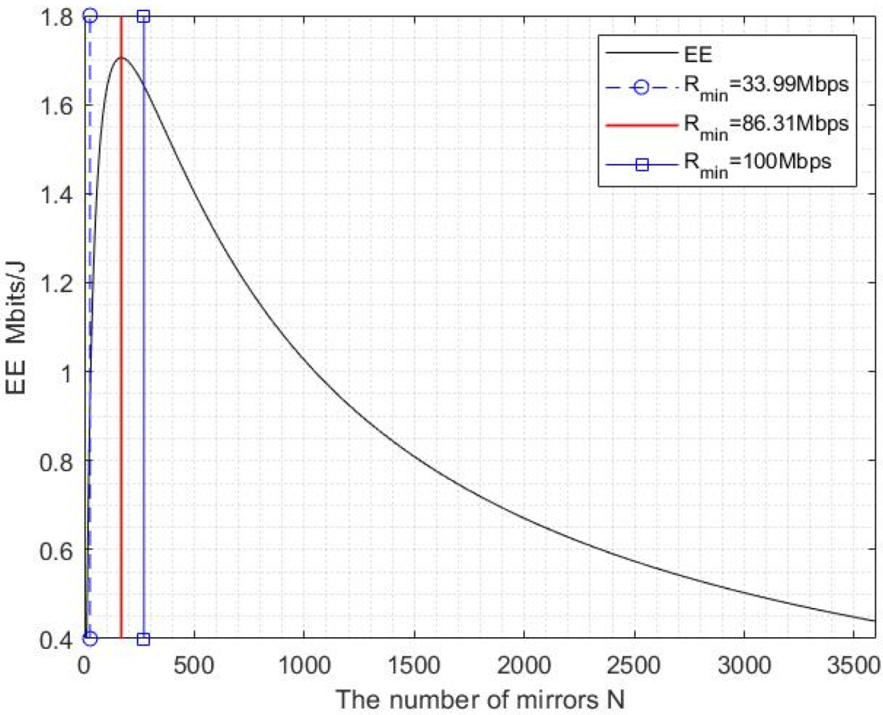
4.2.1. EE Performance with Different R m i n

The minimum achievable rate R m i n can represent the effectiveness of the communication system. According to Formula (48), R m i n can affect the starting iterative value of N. Figure 4 illustrates the EE versus N with different R m i n .
As can be seen from Figure 4, EE shows a trend of increasing first and then decreasing monotonically with the increasing of N, itmeans that EE(N) is a unimodal function, which is consistent with the proof in the paper. With the different R m i n , the iterative range N = { N + | N _ N N ¯ } changes. When R m i n < 33.99   Mbps , the iterative range of N is independent of R m i n . This is because min { N + | R ( N ) R m i n } σ γ t η H 1 P i , and 1 H 1 δ σ γ t η H 1 P i , so the starting iterative point of N is N _ = m i n { N + | N σ γ t η H 1 P i } . When R m i n 33.99   Mbps , min { N + | R ( N ) R m i n } σ γ t η H 1 P i 1 H 1 δ , N _ = min { N + | R ( N ) R m i n } .
When 33.99   Mbps R m i n 86.31   Mbps , E E ( N ) increases first and then decreases monotonically. The binary search method proposed can be used to find N o p t . When 86.31   Mbps R m i n R ( N ¯ ) , such as R m i n = 100   Mbps in the Figure 4, E E ( N ) decreases monotonically, so N o p t = N _ and E E m a x ( N ) = E E ( N _ ) . When R m i n > R ( N ¯ ) , the achievable rate cannot meet the requirements and N o p t does not exist.
Since the changing of R m i n will changes the iterative range of N, the calculation amount will also be different when finding N o p t . Table 3 gives N o p t and iterations with different R m i n .
As can be seen from the Table 3, when R m i n = 40 ,   50 ,   60 ,   70 ,   80   Mbps , N o p t = 168 . This is consistent with the previous analysis. Compared to the total number of mirrors in the IRS N m a x = 3600 , E E ( N ) can be maximized only using 4.67% of the total number of mirrors in IRS after optimization. The BSCI algorithm needs 12 iterations to find N o p t , which reduces the amount of computation by 10 5 orders of magnitude, compared with the Bubble Sort method. When R m i n = 90 ,   100   Mbps , E E ( N ) decreases monotonically and N o p t increases gradually. The BSCI algorithm only needs one iteration to find N o p t . However, the Bubble Sort method still needs a lot of computation. Therefore, the BSCI algorithm is more efficient.

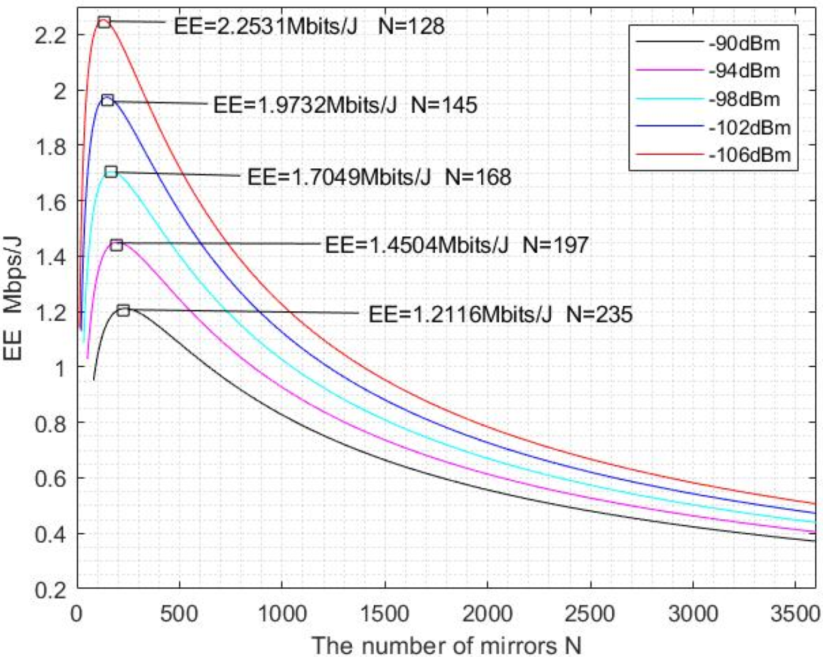
4.2.2. EE Performance with Different σ 2

For VVLC, the noise will affect the EE performance, especially the background light noise. To facilitate comparison, we set R m i n = 40   Mbps . Figure 5 illustrates the EE versus N with different noise power σ 2 .
As can be seen from Figure 5, E E ( N ) increases first and then decreases with different noise power σ 2 , which is a unimodal function. When the number of mirrors in IRS is constant, the EE becomes larger with the smaller noise power. When the number of mirrors is fixed, the denominator in Formula (27) is the same and the lower noise power causes SNR to increase, resulting in the continuous increase of R ( N ) , thus E E ( N ) also increases.
With the noise power becoming lower, the N o p t is smaller and E E m a x ( N ) is larger. According to Formula (41), the E E ( N ) is the largest corresponding to N o p t . It can be seen from Formula (27) that when the increasing speed of the numerator is greater than that of the denominator, the E E ( N ) keeps increasing, otherwise, the E E ( N ) keeps decreasing. When the noise power is smaller, the SNR and the R ( N ) is larger. Taking the growth ratio of the adjacent R ( N ) as an example, the denominator in the ratio R ( N + 1 ) / R ( N ) will also become larger, and the ratio will be less than that at high noise power at this time. Therefore, the numerator grows faster than that of the denominator, easily obtaining the maximum E E ( N ) . Taking σ 2 = 106   dBm as an example, the EE has the maximum value only using 128 mirrors. The remaining mirrors in the IRS can be used to support the VLC of multiple vehicles, which improves the utilization of mirrors in the IRS.
However, the lower noise power makes the starting iterative point of N smaller when calculating the maximum EE. This is because when the noise power is lower, R ( N ) is easier to reach R m i n with the increasing of N. The smaller iterative starting point of N means that the iterative range of N increases, which may add some computational complexity for finding N o p t . Table 4 gives N o p t and iterations with different σ 2 .
According to Table 4, as the noise power decreases, the number of iterations requirement using the Bubble Sort method increases. Even if the iterative range of N changes, the computational complexity using BSCI algorithm changes little, N o p t can still be found quickly without bringing unexpected complexity to the system. Therefore, the BSCI algorithm has better performance.
As can been from Table 4, it is easier to reach the E E m a x ( N ) with lower noise power, and fewer mirrors are required. This is because the growth rate of the numerator in Formula (27) becomes faster when the SNR is smaller. Therefore, reducing noise power is an effective way to obtain higher EE using fewer mirrors. In VVLC, the background light is the main source of the noise. Although the background light noise cannot be eliminated, the optical filters can be considered to reduce the interference of background light and noise power which can improve EE and resource efficiency.

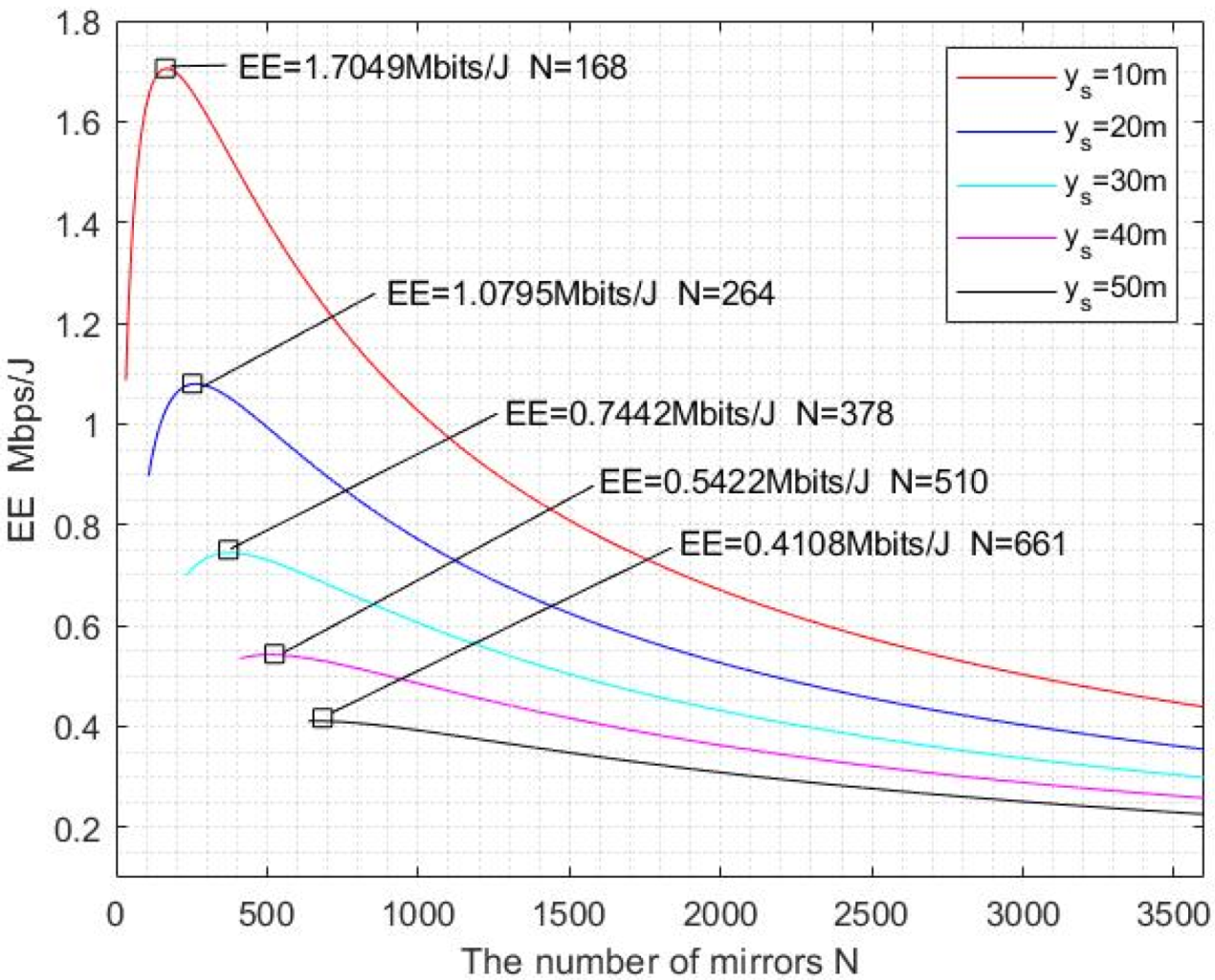
4.2.3. EE Performance with Different y s

y s represents the distance between the vehicle and the IRS in the direction of the road. Since the vehicle is moving, y s is dynamically changing. Figure 6 illustrates the EE versus N with different y s when R m i n = 40   Mbps and σ 2 = 98   dBm .
As can be seen from Figure 6, EE increases first and then decreases when y s = 10 ,   20 ,   30 ,   40 ,   50   m , which is a unimodal function. When the y s is smaller, the larger E E ( N ) is obtained using the same number of mirrors. According to Formula (6), the increase of y s means that R i , j D and R i , j S are increase, resulting that the channel gain corresponding to each mirror decreases. The reduction of channel gain makes the received power and the SNR smaller. In this way, R ( N ) and EE will also be reduced.
Like the analysis in Section 4.2.3, with the smaller y s , the E E ( N ) can reach the maximum value using fewer mirrors and E E m a x ( N ) is also larger at the same time. Taking y s = 10   m as an example, the EE can reach the maximum value using 168 mirrors. The N o p t is reduced 74.6% and E E m a x ( N ) is increased by 4.15 times compared to y s = 50   m .
The smaller y s causes the smaller the iterative starting point of N, so that the iterative range of N used to solve N o p t becomes larger. If the iterative range of N is larger, it is easy to cause the amount of computation becomes larger. Table 5 gives N o p t and iterations with different y s .
As can be seen from Table 5, with the increasing of y s , the iterative number of the Bubble Sort method decreases. This is because the increase of y s causes the starting iterative point of N to become large, thus the range of iteration reduces. Compared with the bubbling method, the BSCI algorithm has fewer iterations and computations.
When the vehicle is moving, the distance between the vehicle and the IRS is constantly changing. When the distance is closer, N o p t is smaller and E E ( N ) is higher. To improve the performance of the N o p t and E E ( N ) , the distance between vehicle and IRS should be optimized. The multiple IRSs can be installed using the existing traffic infrastructures, and the distance between adjacent IRS is not too large, so that the distance is controlled within an appropriate range, which can solve this problem.

5. Conclusions

Energy efficiency is an important indicator to measure the energy consumption of communication systems. In this paper, the VLC system via mirror array-based IRS for parallel vehicles is designed first, and the calculation formula of channel gain is given. Then, the achievable rate and power consumption of the system are analyzed, and the calculation method of EE is given. On this basis, considering the non-negative and real of the transmitted signal, the maximum power consumption satisfied luminous ability and eye safety, the minimum achievable rate, and the required BER, the optimization problem of the number of mirrors under EE maximization is proposed. Under the existing constraints, it is proved that E E ( N ) is a unimodal function. To quickly find the optimal value of the number of mirrors, the BSCI algorithm is proposed. By comparing the optimal number of mirrors corresponding to different R m i n , σ 2 , y s , we can know that different parameter changes will bring the different iterative range of the number of mirrors, and effect the optimal number of mirrors. Compared with the Bubble Sort method, the BSCI algorithm reduces the amount of computation by 10 5 orders of magnitude, and can quickly find the optimal number of mirrors and the maximum value of EE, which is an effective algorithm.
The numerical results show that when the EE corresponding to R m i n is less than the E E m a x ( N ) , E E ( N ) increases first and then decreases. Otherwise, E E ( N ) decreases monotonically, and the E E m a x ( N ) obtained at this time is smaller than that in the previous case. Therefore, it is necessary to select an appropriate R m i n according to the actual communication needs of the vehicle. This requires consideration of the tradeoff between the EE and achievable rate. When noise power increases, E E ( N ) becomes smaller with the same number of mirrors. Therefore, it is necessary to reduce noise power to obtain a smaller number of optimized mirrors and higher EE, especially background light noise. The use of optical elements, such as optical filters, can be considered. As y s increases, the distance between the vehicle and IRS is longer, resulting in the optimal number of mirrors increasing and E E ( N ) decreasing. To solve this problem, it can be considered to install multiple IRSs that the distance between the vehicle and the IRS is within a controllable range, which can improve the efficiency of the mirrors in the IRS and the performance of EE.

Author Contributions

Conceptualization, L.Z. and H.Z.; methodology, L.Z.; validation, L.Z., H.Z. and J.L.; formal analysis, W.Z.; investigation, L.Z.; data curation, H.Z.; writing—original draft preparation, L.Z.; writing—review and editing, J.L.; visualization, L.Z.; supervision, J.L.; project administration, J.L.; funding acquisition, J.L. All authors have read and agreed to the published version of the manuscript.

Funding

This research was funded by the National Natural Science Foundation of China under Grant 61966007 and 61961007, the Basic Ability Improvement Project of Young and Middle-Aged Teachers in Guangxi Universities, grant number 2021KY0217; Key Laboratory of Cognitive Radio and Information Processing, Ministry of Education under Grants CRKL170110, CRKL180201, and CRKL180106, and the Guangxi Key Laboratory of Wireless Wideband Communication and Signal Processing, Guilin University of Electronic Technology (GXKL0619204, GXKL06200116).

Institutional Review Board Statement

Not applicable.

Informed Consent Statement

Not applicable.

Data Availability Statement

Not applicable.

Acknowledgments

The authors wish to thank the anonymous reviewers for their valuable suggestions.

Conflicts of Interest

The authors declare no conflict of interest.

References

  1. Reza, S.; Oliveira, H.S.; Machado, J.J.M.; Tavares, J. Urban Safety: An Image-Processing and Deep-Learning-Based Intelligent Traffic Management and Control System. Sensors 2021, 21, 7705. [Google Scholar] [CrossRef] [PubMed]
  2. Lv, Z.; Lou, R.; Singh, A.K. AI Empowered Communication Systems for Intelligent Transportation Systems. IEEE Trans. Intell. Transp. Syst. 2021, 22, 4579–4587. [Google Scholar] [CrossRef]
  3. Zadobrischi, E.; Cosovanu, L.-M.; Dimian, M. Traffic Flow Density Model and Dynamic Traffic Congestion Model Simulation Based on Practice Case with Vehicle Network and System Traffic Intelligent Communication. Symmetry 2020, 12, 1172. [Google Scholar] [CrossRef]
  4. Yang, Y.; Hua, K. Emerging Technologies for 5G-Enabled Vehicular Networks. IEEE Access 2019, 7, 181117–181141. [Google Scholar] [CrossRef]
  5. He, R.; Schneider, C.; Ai, B.; Wang, G.; Zhong, Z.; Dupleich, D.A.; Thomae, R.S.; Boban, M.; Luo, J.; Zhang, Y. Propagation Channels of 5G Millimeter-Wave Vehicle-to-Vehicle Communications: Recent Advances and Future Challenges. IEEE Veh. Technol. Mag. 2020, 15, 16–26. [Google Scholar] [CrossRef]
  6. do Vale Saraiva, T.; Campos, C.A.V.; Fontes, R.d.R.; Rothenberg, C.E.; Sorour, S.; Valaee, S. An Application-Driven Framework for Intelligent Transportation Systems Using 5G Network Slicing. IEEE Trans. Intell. Transp. Syst. 2021, 22, 5247–5260. [Google Scholar] [CrossRef]
  7. Ning, Z.; Zhang, K.; Wang, X.; Obaidat, M.S.; Guo, L.; Hu, X.; Hu, B.; Guo, Y.; Sadoun, B.; Kwok, R.Y.K. Joint Computing and Caching in 5G-Envisioned Internet of Vehicles: A Deep Reinforcement Learning-Based Traffic Control System. IEEE Trans. Intell. Transp. Syst. 2021, 22, 5201–5212. [Google Scholar] [CrossRef]
  8. Chen, C.; Yuru, T.; Yueping, C.; Min, L. Fairness-aware hybrid NOMA/OFDMA for bandlimited multi-user VLC systems. Opt. Express 2021, 29, 42265–42275. [Google Scholar] [CrossRef]
  9. Chen, C.; Zhong, X.; Fu, S.; Jian, X.; Liu, M.; Yang, H.; Alphones, A.; Fu, H.Y. OFDM-Based Generalized Optical MIMO. J. Lightw. Technol. 2021, 39, 6063–6075. [Google Scholar] [CrossRef]
  10. Miao, P.; Yin, W.; Peng, H.; Yao, Y. Study of the Performance of Deep Learning-Based Channel Equalization for Indoor Visible Light Communication Systems. Photonics 2021, 8, 453. [Google Scholar] [CrossRef]
  11. Chen, C.; Fu, S.; Jian, X.; Liu, M.; Deng, X.; Ding, Z. NOMA for Energy-Efficient LiFi-Enabled Bidirectional IoT Communication. IEEE Trans. Commun. 2021, 69, 1693–1706. [Google Scholar] [CrossRef]
  12. Arai, S.; Tang, Z.; Nakayama, A.; Takata, H.; Yendo, T. Rotary LED Transmitter for Improving Data Transmission Rate of Image Sensor Communication. IEEE Photonics J. 2021, 13, 1–11. [Google Scholar] [CrossRef]
  13. Takahashi, K.; Kamakura, K.; Kinoshita, M.; Yamazato, T. Luminance Inversion for Parallel Transmission Visible Light Communication Between LCD and Image Sensor Camera. J. Lightw. Technol. 2021, 39, 6759–6767. [Google Scholar] [CrossRef]
  14. Sun, X.; Shi, W.; Cheng, Q.; Liu, W.; Wang, Z.; Zhang, J. An LED Detection and Recognition Method Based on Deep Learning in Vehicle Optical Camera Communication. IEEE Access 2021, 9, 80897–80905. [Google Scholar] [CrossRef]
  15. Zhu, Z.; Wei, S.; Liu, R.; Hong, Z.; Zheng, Z.; Fan, Z.; Ma, D. Freeform surface design for high-efficient LED low-beam headlamp lens. Opt. Commun. 2020, 477, 126269. [Google Scholar] [CrossRef]
  16. Singh, R.; Mochizuki, M.; Yamada, T.; Nguyen, T. Cooling of LED headlamp in automotive by heat pipes. Appl. Therm. Eng. 2020, 166, 114733. [Google Scholar] [CrossRef]
  17. Memedi, A.; Dressler, F. Vehicular Visible Light Communications: A Survey. IEEE Commun. Surv. Tutor. 2021, 23, 161–181. [Google Scholar] [CrossRef]
  18. Turan, B.; Coleri, S. Machine Learning Based Channel Modeling for Vehicular Visible Light Communication. IEEE Trans. Veh. Technol. 2021, 70, 9659–9672. [Google Scholar] [CrossRef]
  19. Alsalami, F.M.; Ahmad, Z.; Zvanovec, S.; Haigh, P.A.; Haas, O.C.L.; Rajbhandari, S. Statistical channel modelling of dynamic vehicular visible light communication system. Veh. Commun. 2021, 29, 100339. [Google Scholar] [CrossRef]
  20. Karbalayghareh, M.; Miramirkhani, F.; Eldeeb, H.B.; Kizilirmak, R.C.; Sait, S.M.; Uysal, M. Channel Modelling and Performance Limits of Vehicular Visible Light Communication Systems. IEEE Trans. Veh. Technol. 2020, 69, 6891–6901. [Google Scholar] [CrossRef]
  21. Luo, P.; Ghassemlooy, Z.; Minh, H.L.; Bentley, E.; Burton, A.; Tang, X. Performance analysis of a car-to-car visible light communication system. Appl. Opt. 2015, 54, 1696–1706. [Google Scholar] [CrossRef]
  22. Huang, C.; Zappone, A.; Alexandropoulos, G.C.; Debbah, M.; Yuen, C. Reconfigurable Intelligent Surfaces for Energy Efficiency in Wireless Communication. IEEE Trans. Wirel. Commun. 2019, 18, 4157–4170. [Google Scholar] [CrossRef] [Green Version]
  23. Pan, C.; Ren, H.; Wang, K.; Elkashlan, M.; Nallanathan, A.; Wang, J.; Hanzo, L. Intelligent Reflecting Surface Aided MIMO Broadcasting for Simultaneous Wireless Information and Power Transfer. IEEE J. Sel. Areas Commun. 2020, 38, 1719–1734. [Google Scholar] [CrossRef]
  24. Du, H.; Zhang, J.; Cheng, J.; Ai, B. Millimeter Wave Communications with Reconfigurable Intelligent Surfaces: Performance Analysis and Optimization. IEEE Trans. Commun. 2021, 69, 2752–2768. [Google Scholar] [CrossRef]
  25. Sur, S.N.; Bera, R. Intelligent reflecting surface assisted MIMO communication system: A review. Phys. Commun. 2021, 47, 101386. [Google Scholar] [CrossRef]
  26. Masini, B.M.; Silva, C.M.; Balador, A. The Use of Meta-Surfaces in Vehicular Networks. J. Sens. Actuator Netw. 2020, 9, 15. [Google Scholar] [CrossRef] [Green Version]
  27. Makarfi, A.U.; Rabie, K.M.; Kaiwartya, O.; Adhikari, K.; Li, X.; Quiroz-Castellanos, M.; Kharel, R. Reconfigurable Intelligent Surfaces-Enabled Vehicular Networks: A Physical Layer Security Perspective. arXiv 2020, arXiv:2004.11288. [Google Scholar]
  28. Dingel, B.B.; Tsukamoto, K.; Mikroulis, S.; Deng, P.; Kavehrad, M.; Lou, Y. MEMS-based beam-steerable free-space optical communication link for reconfigurable wireless data center. In Proceedings of the Broadband Access Communication Technologies XI, San Francisco, CA, USA, 28 January 2017; Volume 10128, p. 1012805. [Google Scholar]
  29. Cao, Z.; Zhang, X.; Osnabrugge, G.; Li, J.; Vellekoop, I.M.; Koonen, A.M.J. Reconfigurable beam system for non-line-of-sight free-space optical communication. Light Sci. Appl. 2019, 8, 69. [Google Scholar] [CrossRef]
  30. Jamali, V.; Ajam, H.; Najafi, M.; Schmauss, B.; Schober, R.; Poor, H.V. Intelligent Reflecting Surface-assisted Free-space Optical Communications. IEEE Commun. Mag. 2021, 59, 57–63. [Google Scholar] [CrossRef]
  31. Abdelhady, A.M.; Salem, A.K.S.; Amin, O.; Shihada, B.; Alouini, M.-S. Visible Light Communications via Intelligent Reflecting Surfaces: Metasurfaces vs Mirror Arrays. IEEE Open J. Commun. Soc. 2021, 2, 1–20. [Google Scholar] [CrossRef]
  32. Alizadeh Jarchlo, E.; Eso, E.; Doroud, H.; Siessegger, B.; Ghassemlooy, Z.; Caire, G.; Dressler, F. Li-Wi: An upper layer hybrid VLC-WiFi network handover solution. Ad Hoc Netw. 2022, 124, 102705. [Google Scholar] [CrossRef]
  33. Basar, E. Reconfigurable Intelligent Surface-Based Index Modulation: A New Beyond MIMO Paradigm for 6G. IEEE Trans. Commun. 2020, 68, 3187–3196. [Google Scholar] [CrossRef] [Green Version]
  34. Zhang, J.; Bjornson, E.; Matthaiou, M.; Ng, D.W.K.; Yang, H.; Love, D.J. Prospective Multiple Antenna Technologies for Beyond 5G. IEEE J. Sel. Areas Commun. 2020, 38, 1637–1660. [Google Scholar] [CrossRef]
  35. Bjornson, E.; Ozdogan, O.; Larsson, E.G. Intelligent Reflecting Surface Versus Decode-and-Forward: How Large Surfaces are Needed to Beat Relaying? IEEE Wirel. Commun. Lett. 2020, 9, 244–248. [Google Scholar] [CrossRef] [Green Version]
  36. Wang, J.; Hu, Q.; Wang, J.; Chen, M.; Wang, J. Tight bounds on channel capacity for dimmable visible light communications. J. Lightw. Technol. 2013, 31, 3771–3779. [Google Scholar] [CrossRef]
  37. Ma, S.; Yang, R.; Li, H.; Dong, Z.-L.; Gu, H.; Li, S. Achievable rate with closed-form for SISO channel and broadcast channel in visible light communication networks. J. Lightw. Technol. 2017, 35, 2778–2787. [Google Scholar] [CrossRef]
  38. Ma, S.; Yang, R.; He, Y.; Lu, S.; Zhou, F.; Al-Dhahir, N.; Li, S. Achieving Channel Capacity of Visible Light Communication. IEEE Syst. J. 2021, 15, 1652–1663. [Google Scholar] [CrossRef]
  39. Sun, S.; Yang, F.; Song, J. Sum Rate Maximization for Intelligent Reflecting Surface-Aided Visible Light Communications. IEEE Commun. Lett. 2021, 25, 3619–3623. [Google Scholar] [CrossRef]
  40. Ma, S.; Zhang, T.; Lu, S.; Li, H.; Wu, Z.; Li, S. Energy Efficiency of SISO and MISO in Visible Light Communication Systems. J. Lightw. Technol. 2018, 36, 2499–2509. [Google Scholar] [CrossRef]
  41. Teixeira, L.; Loose, F.; Barriquello, C.H.; Reguera, V.A.; Costa, M.A.D.; Alonso, J.M. On Energy Efficiency of Visible Light Communication Systems. IEEE J. Emerg. Sel. Top. Power Electron. 2021, 9, 6396–6407. [Google Scholar] [CrossRef]
  42. Cao, B.; Chen, M.; Yang, Z.; Zhang, M.; Zhao, J.; Chen, M. Reflecting the Light: Energy Efficient Visible Light Communication with Reconfigurable Intelligent Surface. In Proceedings of the 2020 IEEE 92nd Vehicular Technology Conference, Victoria, BC, Canada, 18 November–16 December 2020. [Google Scholar]
  43. Akanegawa, M.; Tanaka, Y.; Nakagawa, M. Basic study on traffic information system using LED traffic lights. IEEE Trans. Intell. Transp. Syst. 2001, 2, 197–203. [Google Scholar] [CrossRef]
  44. Komine, T.; Nakagawa, M. Fundamental analysis for visible-light communication system using LED lights. IEEE Trans. Consum. Electron. 2004, 50, 100–107. [Google Scholar] [CrossRef]
Figure 1. Application scenario of the VLC system via mirror array-based IRS for parallel vehicles.
Photonics 09 00129 g001
Figure 2. Model of the VLC system via mirror array-based IRS for parallel vehicles.
Photonics 09 00129 g002
Figure 3. The total power consumption model in the VLC system via mirror array-based IRS.
Photonics 09 00129 g003
Figure 4. EE versus N with different R m i n .
Photonics 09 00129 g004
Figure 5. EE versus N with different noise power σ 2 .
Photonics 09 00129 g005
Figure 6. EE versus N with different y s .
Photonics 09 00129 g006
Table 1. Mathematical notations and definitions.
NotationsDefinitions
x s X-coordinate of the transmitter S as measured from the upper left corner of the IRS
y s Y-coordinate of the transmitter S as measured from the IRS along the road
z s Z-coordinate of the transmitter S as measured from the upper left corner of the IRS
x d X-coordinate of the receiver D as measured from the upper left corner of the IRS
y d Y-coordinate of the receiver D as measured from the IRS along the road
h d Z-coordinate of D as measured from the transmitter S
w m Width of each mirror
h m Height of each mirror
Δ w m Edge-to-edge inter-mirror separation distances along the x-axis
Δ h m Edge-to-edge inter-mirror separation distances along the z-axis
n k The number of mirrors of each column in the IRS
n l The number of mirrors of each row in the IRS
ρ Mirror reflection efficiency
P i Transmitted power
m Order of Lambertian emission
Φ 1 / 2 Half-power semiangle of an LED
θ R i , j S Irradiance angle of the LED from the transmitter S to mirror R i , j
θ R i , j D Incidence angle of the PD from mirror R i , j to the receiver D
ϖ Current-to-light conversion efficiency
A d Physical area of the PD
T s ( · ) Optical filter gain
g ( θ ) Optical concentrator gain
μ Refractive index
Ψ c FOV of the PD
ζ Efficiency of the transmit power amplifier
I D C DC-offset
A Amplitude constraint of the signal
ε The variance of the signal
η Responsivity of the PD
N Total number of mirrors in the IRS
B VLC system modulation bandwidth
P m a x The maximum power threshold
B E R t The maximum acceptable BER
N m a x The maximum number
E ( · ) Expectation operator
Table 2. Main simulation parameters.
ParameterValue
z m 0.62 m
( w m , h m ) (0.01, 0.01) m
Φ 1 / 2 60 deg.
Ψ c 35 deg.
A d 1.0 cm2
T s 1.0
μ 1.5
ϖ 0.44 W/A
ρ 0.8
η 0.54 A/W
ζ 1.2
B20 MHz
Table 3. N o p t and iterations with different R m i n .
R m i n   ( Mbps ) N o p t E E m a x ( N )   ( Mbits / J ) Iterations of Bubble Sort MethodIterations of BSCI
Algorithm
401681.7049636352812
501681.7049631368112
601681.7049624281112
701681.7049614426512
801681.7049600484512
901911.700458123451
1002701.641755461151
Table 4. N o p t and iterations with different σ 2 .
σ 2   ( dBm ) N o p t E E m a x ( N )   ( Mbits / J ) Iterations of Bubble Sort MethodIterations of BSCI
Algorithm
−902351.2116618992112
−941971.4504629592611
−981681.7049636352812
−1021451.9732640641012
−1061282.2531643507812
Table 5. N o p t and iterations with different y s .
y s   ( m ) N o p t E E m a x ( N )   ( Mbits / J ) Iterations of Bubble Sort MethodIterations of BSCI
Algorithm
101681.7049636352812
202641.0795609877812
303780.7442566666112
405100.5422508964511
506610.4108439413011
Publisher’s Note: MDPI stays neutral with regard to jurisdictional claims in published maps and institutional affiliations.

