Fluorescence Mapping of Agricultural Fields Utilizing Drone-Based LIDAR

 ,
,  ,
,  and
and 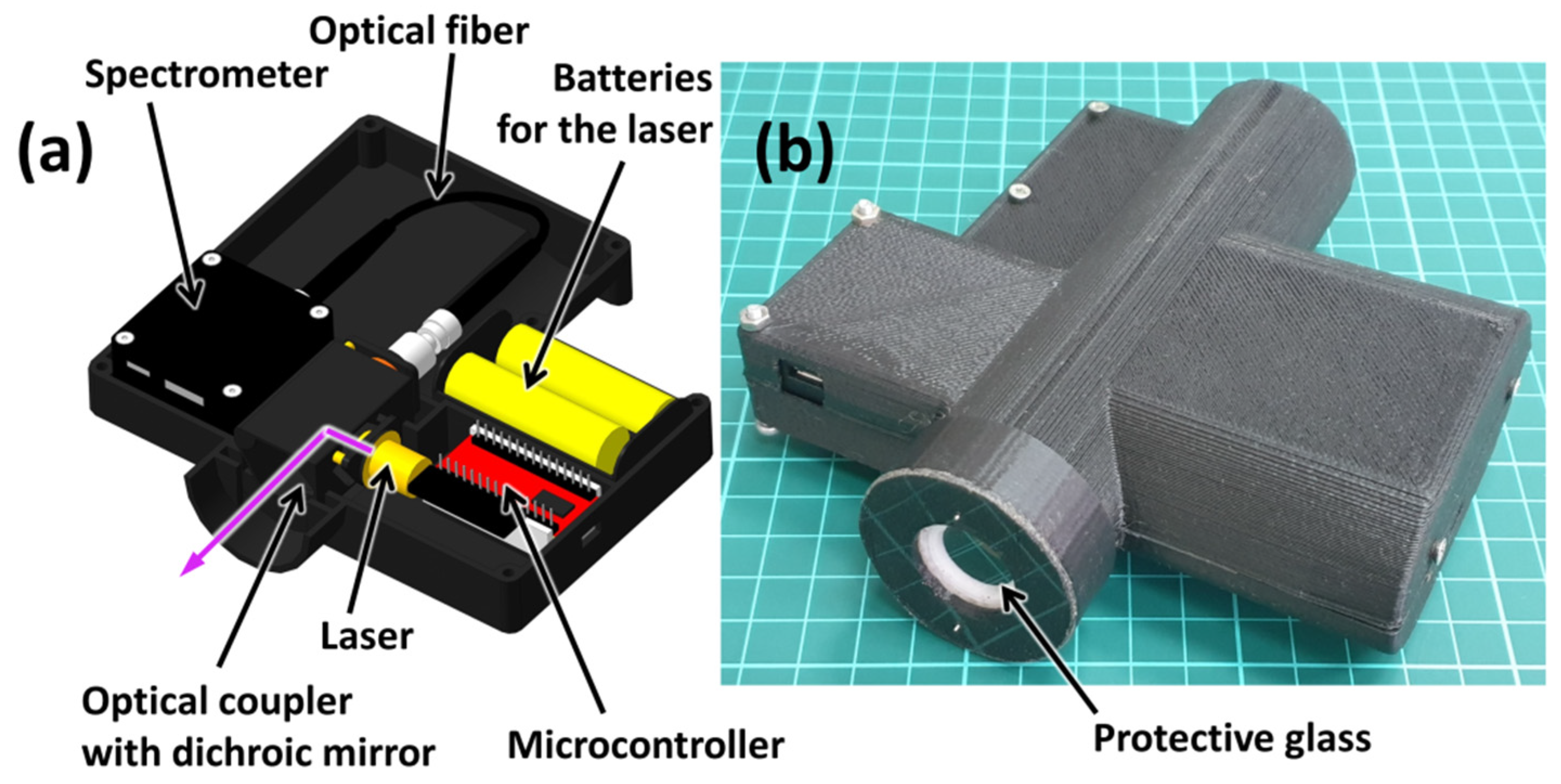
Abstract
1. Introduction
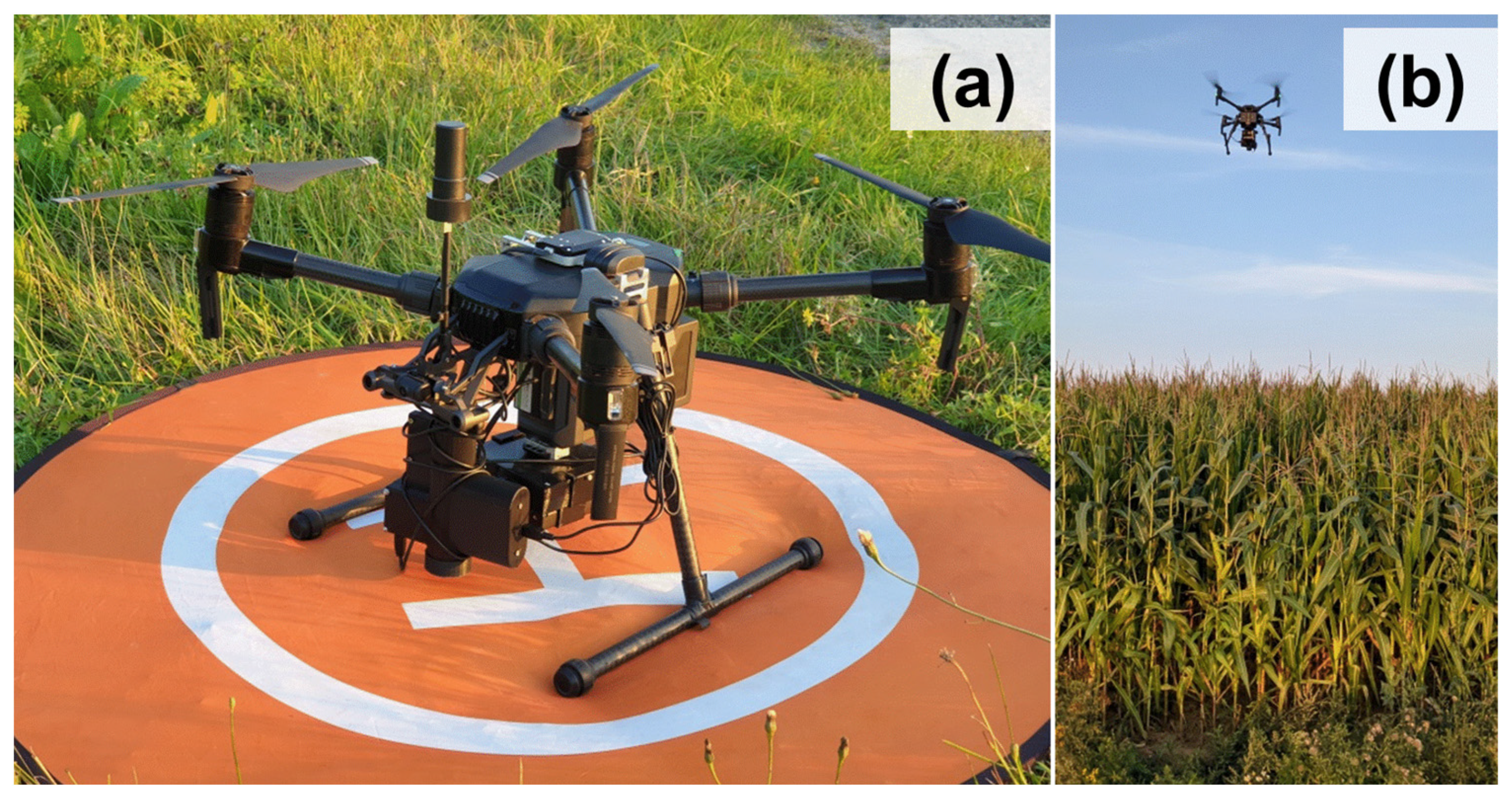
2. Experiment
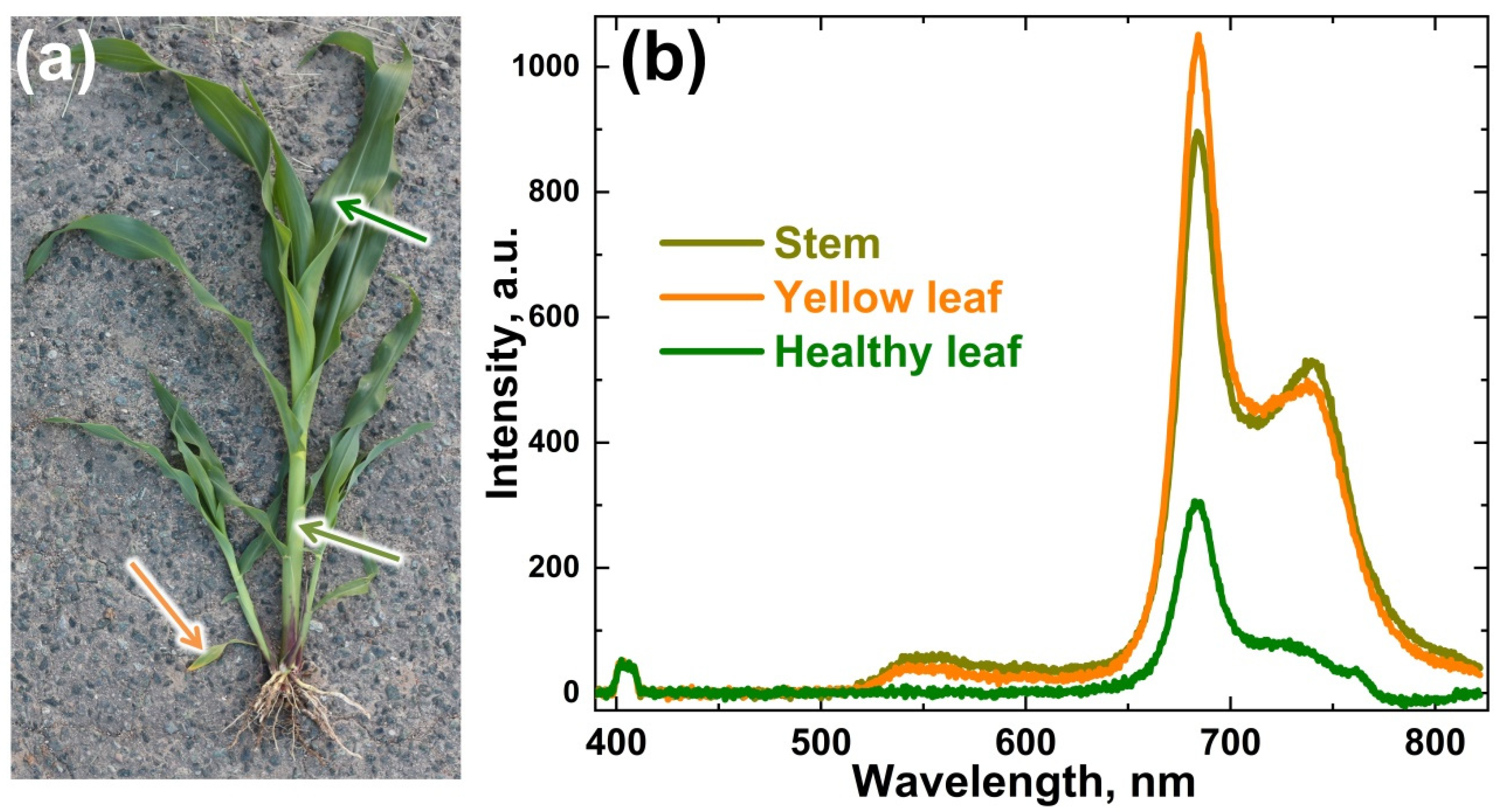
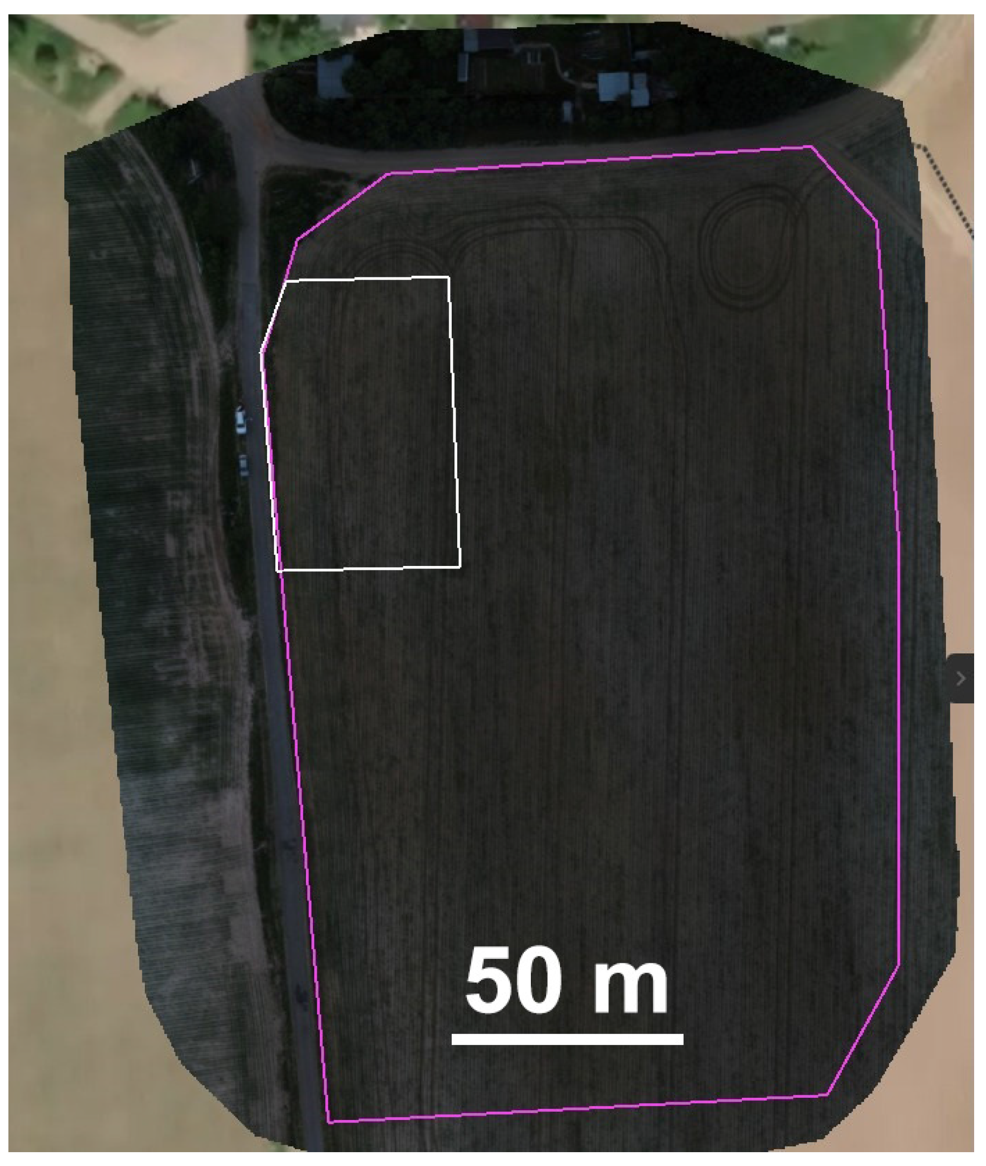
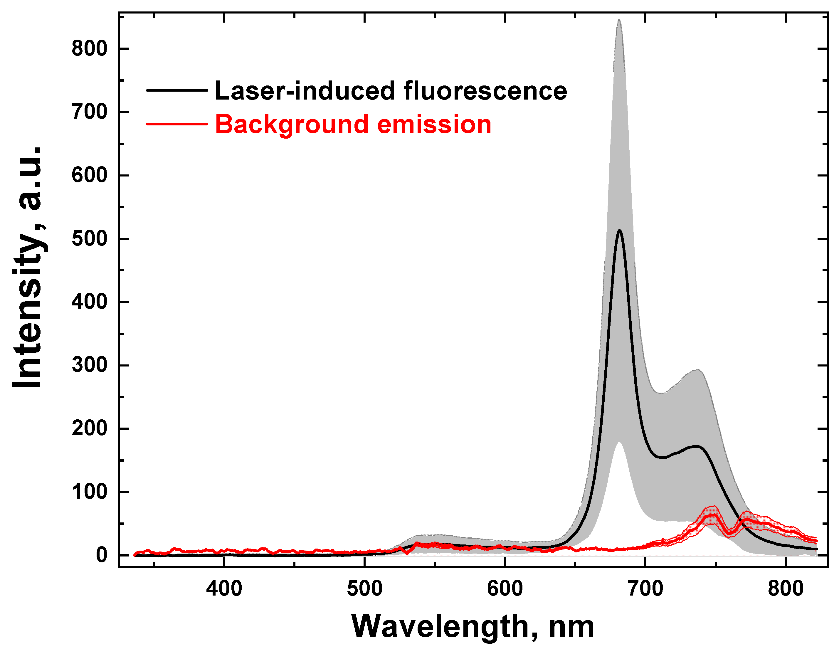
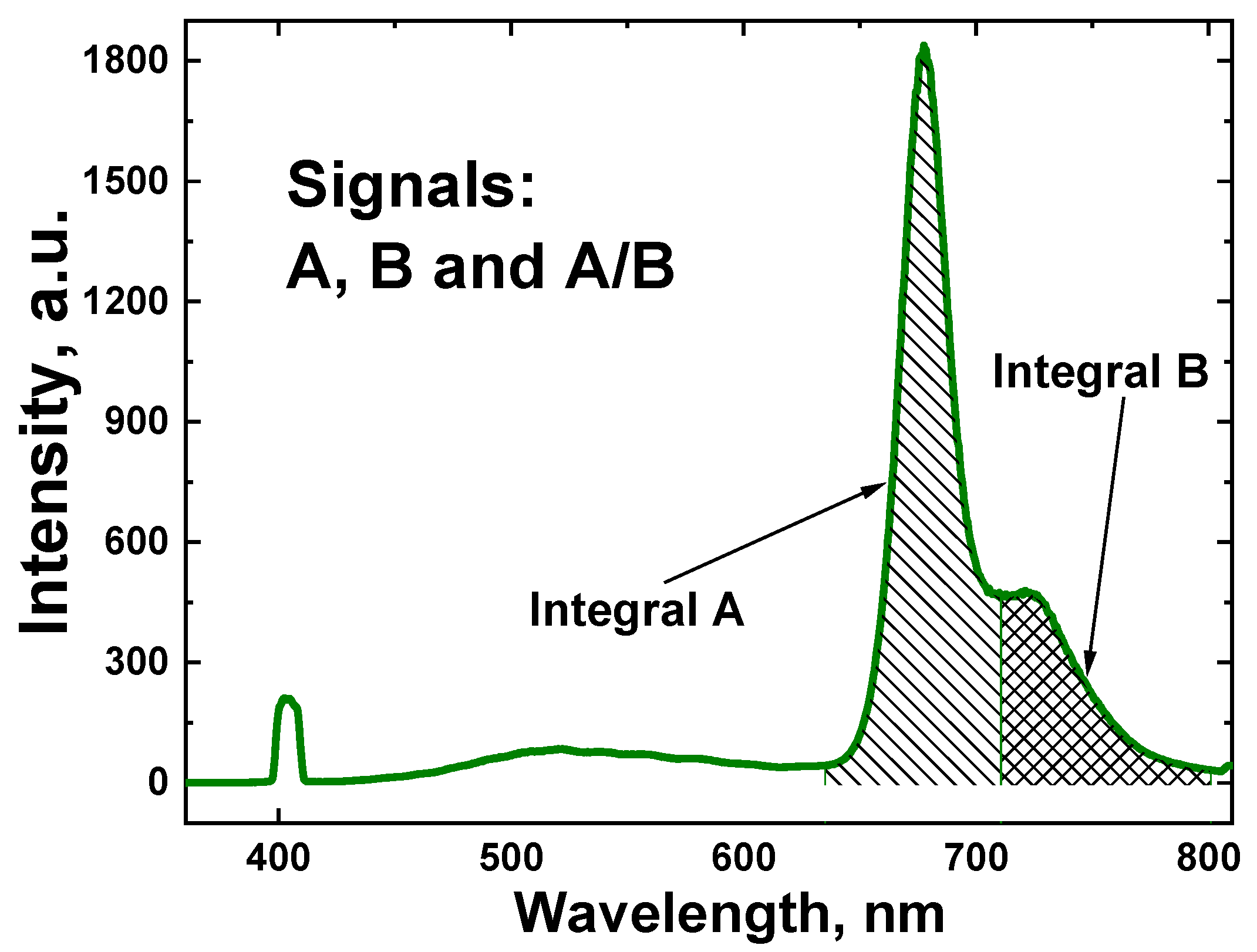
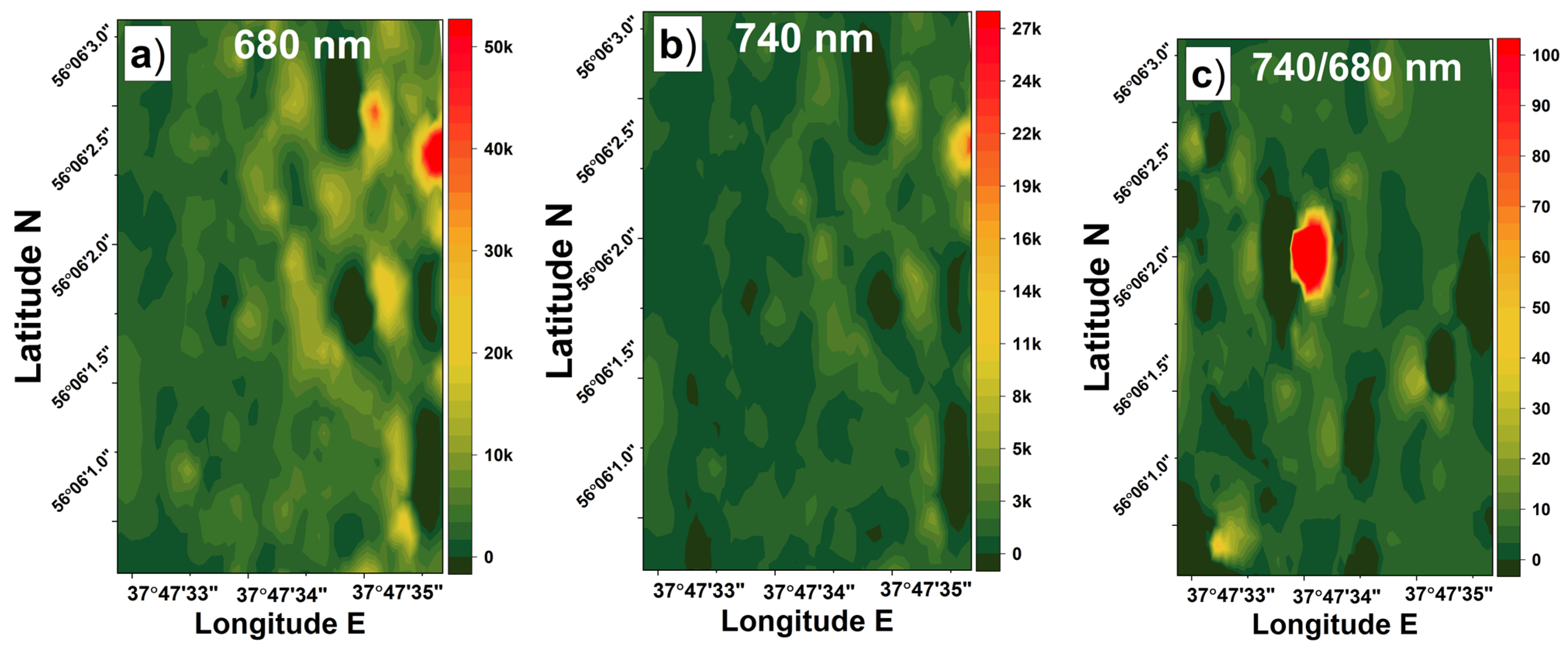
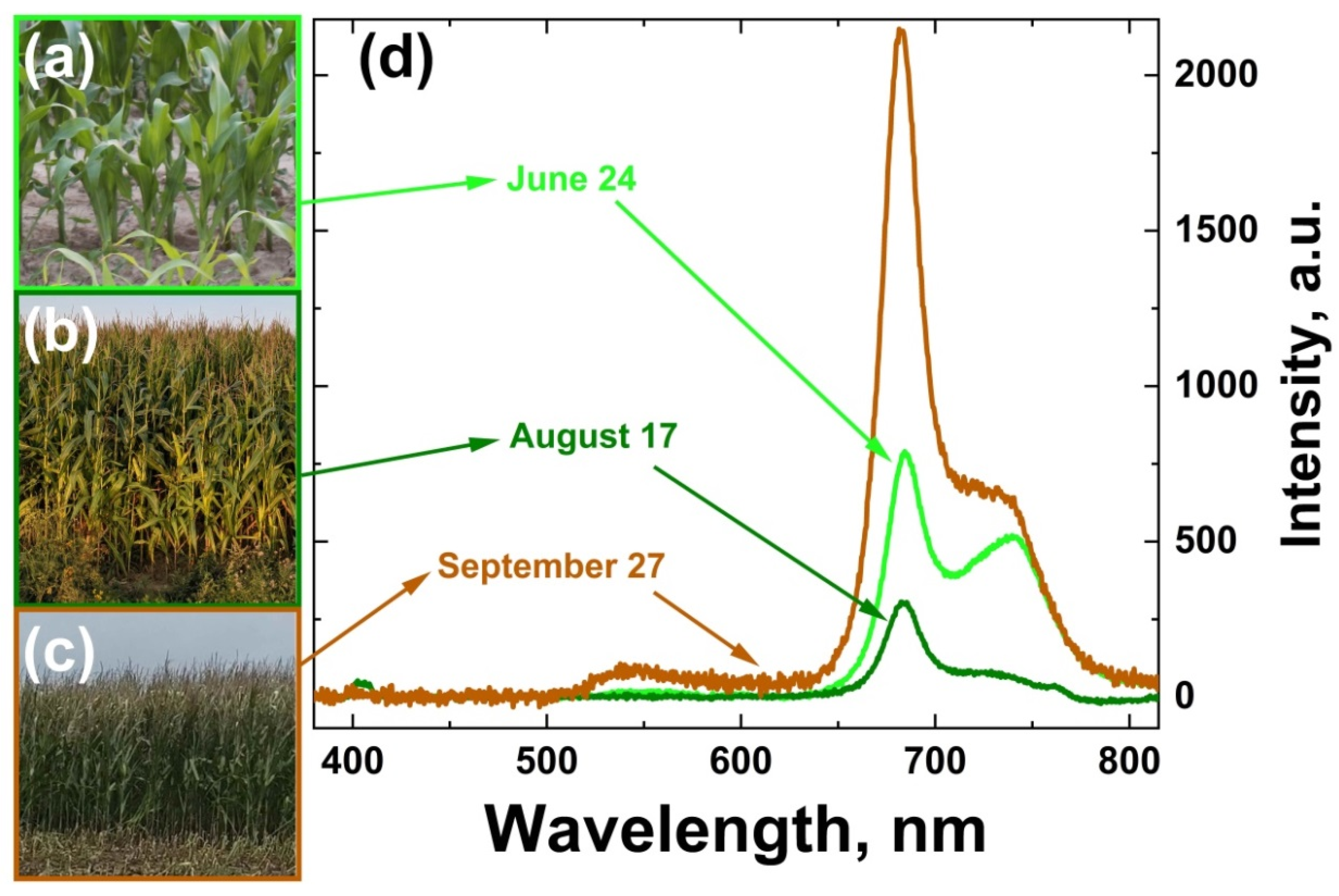
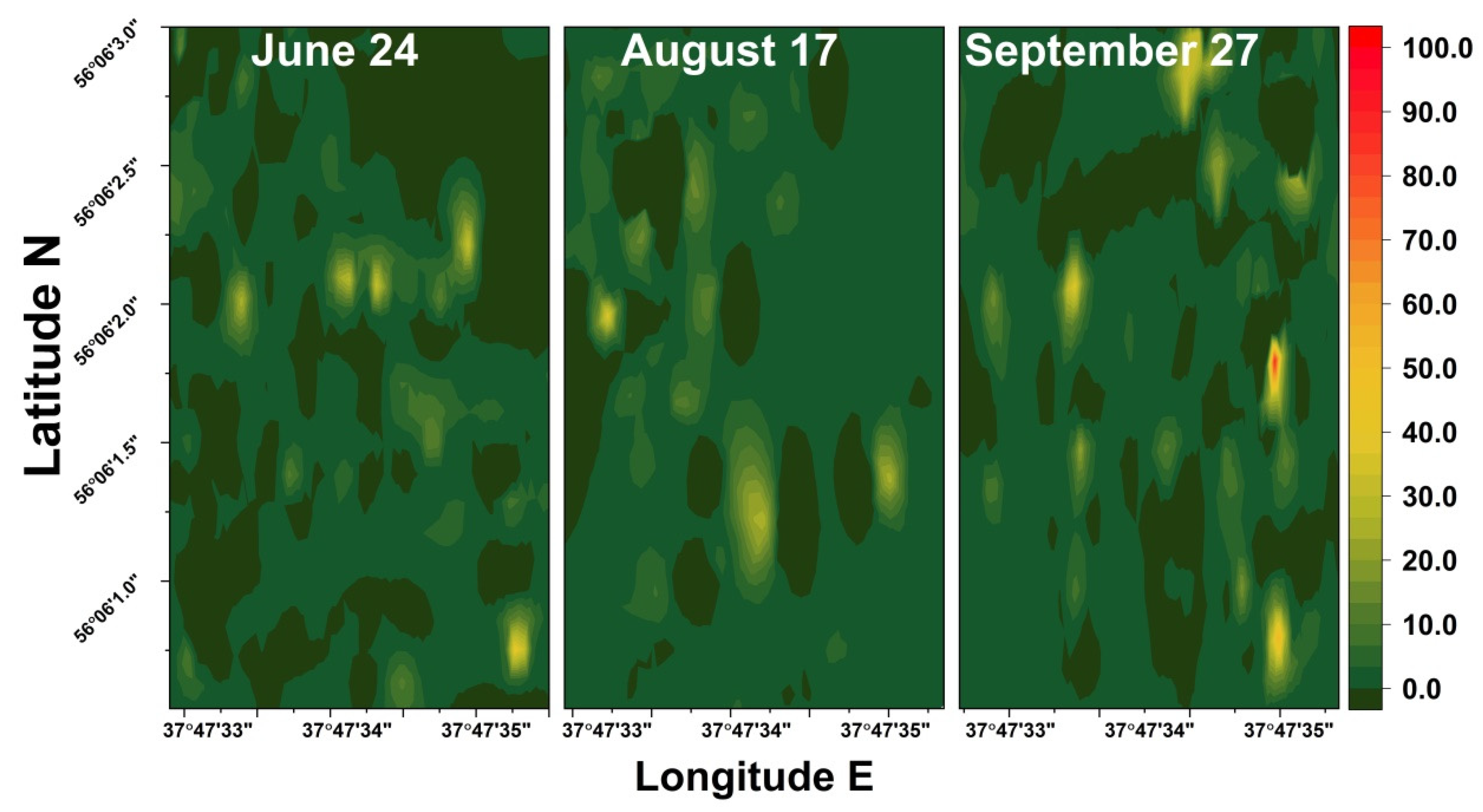
3. Results and Discussion
4. Conclusions
Author Contributions
Funding
Institutional Review Board Statement
Informed Consent Statement
Data Availability Statement
Conflicts of Interest
References
- Chang, A.; Jung, J.; Maeda, M.M.; Landivar, J. Crop height monitoring with digital imagery from Unmanned Aerial System (UAS). Comput. Electron. Agric. 2017, 141, 232–237. [Google Scholar] [CrossRef]
- Rudorff, B.; Batista, G. Yield estimation of sugarcane based on agrometeorological-spectral models. Remote Sens. Environ. 1990, 33, 183–192. [Google Scholar] [CrossRef]
- Cozzolino, D. Use of Infrared Spectroscopy for In-Field Measurement and Phenotyping of Plant Properties: Instrumentation, Data Analysis, and Examples. Appl. Spectrosc. Rev. 2014, 49, 564–584. [Google Scholar] [CrossRef]
- Evangelista, C.; Basiricò, L.; Bernabucci, U. An overview on the use of near infrared spectroscopy (NIRS) on farms for the management of dairy cows. Agriculture 2021, 11, 296. [Google Scholar] [CrossRef]
- Brisco, B.; Brown, R.J.; Hirose, T.; McNairn, H.; Staenz, K. Precision agriculture and the role of remote sensing: A review. Can. J. Remote Sens. 1998, 24, 315–327. [Google Scholar] [CrossRef]
- Liaghat, S.; Balasundram, S.K. A review: The role of remote sensing in precision agriculture. Am. J. Agric. Biol. Sci. 2010, 5, 50–55. [Google Scholar] [CrossRef]
- Sishodia, R.P.; Ray, R.L.; Singh, S.K. Applications of remote sensing in precision agriculture: A review. Remote Sens. 2020, 12, 3136. [Google Scholar] [CrossRef]
- Kior, A.; Sukhov, V.; Sukhova, E. Application of reflectance indices for remote sensing of plants and revealing actions of stressors. Photonics 2021, 8, 582. [Google Scholar] [CrossRef]
- Khanal, S.; Kc, K.; Fulton, J.P.; Shearer, S.; Ozkan, E. Remote sensing in agriculture—Accomplishments, limitations, and opportunities. Remote Sens. 2020, 12, 3783. [Google Scholar] [CrossRef]
- Measures, R.M. Laser Remote Sensing: Fundamentals and Applications; John Wiley & Sons, Ltd.: New York, NY, USA, 1984; ISBN 0894646192. [Google Scholar]
- Bunkin, A.; Voliak, K. Laser Remote Sensing of the Ocean: Methods and Applications; Wiley: New York, NY, USA, 2001; ISBN 0471389277. [Google Scholar]
- Lednev, V.N.; Bunkin, A.F.; Pershin, S.M.; Grishin, M.Y.; Artemova, D.G.; Zavozin, V.A.; Sdvizhenskii, P.A.; Nunes, R.A. Remote Laser Induced Fluorescence of Soils and Rocks. Photonics 2021, 8, 411. [Google Scholar] [CrossRef]
- Yang, G.; Tian, Z.; Bi, Z.; Cui, Z.; Sun, F.; Liu, Q. Measurement of the Attenuation Coefficient in Fresh Water Using the Adjacent Frame Difference Method. Photonics 2022, 9, 713. [Google Scholar] [CrossRef]
- Mogili, U.M.R.; Deepak, B. Review on application of drone systems in precision agriculture. Procedia Comput. Sci. 2018, 133, 502–509. [Google Scholar] [CrossRef]
- Mohsan, S.A.H.; Khan, M.A.; Noor, F.; Ullah, I.; Alsharif, M.H. Towards the unmanned aerial vehicles (UAVs): A comprehensive review. Drones 2022, 6, 147. [Google Scholar] [CrossRef]
- Panday, U.S.; Pratihast, A.K.; Aryal, J.; Kayastha, R.B. A Review on Drone-Based Data Solutions for Cereal Crops. Drones 2020, 4, 41. [Google Scholar] [CrossRef]
- Christiansen, M.; Laursen, M.; Jørgensen, R.; Skovsen, S.; Gislum, R. Designing and Testing a UAV Mapping System for Agricultural Field Surveying. Sensors 2017, 17, 2703. [Google Scholar] [CrossRef]
- Grishin, M.Y.; Lednev, V.N.; Sdvizhenskii, P.A.; Pavkin, D.Y.; Nikitin, E.A.; Bunkin, A.F.; Pershin, S.M. Lidar Monitoring of Moisture in Biological Objects. In Proceedings of the Doklady Physics; Springer: Berlin, Germany, 2021; Volume 66, pp. 273–276. [Google Scholar]
- Pershin, S.M.; Bunkin, A.F.; Klinkov, V.K.; Lednev, V.N.; Lushnikov, D.; Morozov, E.G.; Yul’metov, R.N. Remote sensing of Arctic Fjords by Raman lidar: Heat transfer screening by layer of glacier’s relict water. Phys. Wave Phenom. 2012, 20, 212–222. [Google Scholar] [CrossRef]
- Myasnikov, A.V.; Pershin, S.M.; Grishin, M.Y.; Zavozin, V.A.; Makarov, V.S.; Ushakov, A.A. Estimation of the Influence of Meteorological Factors on the Aerosol Lidar Signal in Tunnels above the Elbrus Volcano Chamber. Phys. Wave Phenom. 2022, 30, 119–127. [Google Scholar] [CrossRef]
- Pershin, S.M.; Sobisevich, A.L.; Zavozin, V.A.; Grishin, M.Y.; Lednev, V.N.; Makarov, V.S.; Petkov, V.B.; Ponurovskii, Y.Y.; Fedorov, A.N.; Artemova, D.G. LIDAR Detection of Aerosols in the Tunnel above the Elbrus Volcano Chamber. Bull. Lebedev Phys. Inst. 2022, 49, 36–41. [Google Scholar] [CrossRef]
- Pershin, S.M.; Sobisevich, A.L.; Grishin, M.Y.; Gravirov, V.V.; Zavozin, V.A.; Kuzminov, V.V.; Lednev, V.N.; Likhodeev, D.V.; Makarov, V.S.; Myasnikov, A.V.; et al. Volcanic activity monitoring by unique LIDAR based on a diode laser. Laser Phys. Lett. 2020, 17, 115607. [Google Scholar] [CrossRef]
- Pershin, S.M.; Grishin, M.Y.; Zavozin, V.A.; Kuzminov, V.V.; Lednyov, V.N.; Makarov, V.S.; Myasnikov, A.V.; Tyurin, A.V.; Fedorov, A.N.; Petkov, V.B. Lidar Sensing of Multilayer Fog Evolution in the Inclined Tunnel of the Baksan Neutrino Observatory. Bull. Lebedev Phys. Inst. 2019, 46, 328–332. [Google Scholar] [CrossRef]
- Tsouros, D.C.; Bibi, S.; Sarigiannidis, P.G. A review on UAV-based applications for precision agriculture. Information 2019, 10, 349. [Google Scholar] [CrossRef]
- Tao, H.; Xu, S.; Tian, Y.; Li, Z.; Ge, Y.; Zhang, J.; Wang, Y.; Zhou, G.; Deng, X.; Zhang, Z.; et al. Proximal and remote sensing in plant phenomics: 20 years of progress, challenges, and perspectives. Plant Commun. 2022, 3, 100344. [Google Scholar] [CrossRef] [PubMed]
- Zhang, C.; Kovacs, J.M. The application of small unmanned aerial systems for precision agriculture: A review. Precis. Agric. 2012, 13, 693–712. [Google Scholar] [CrossRef]
- Guo, W.; Carroll, M.E.; Singh, A.; Swetnam, T.L.; Merchant, N.; Sarkar, S.; Singh, A.K.; Ganapathysubramanian, B. UAS-Based Plant Phenotyping for Research and Breeding Applications. Plant Phenomics 2021, 2021, 9840192. [Google Scholar] [CrossRef]
- Lin, Y.-C.; Habib, A. Quality control and crop characterization framework for multi-temporal UAV LiDAR data over mechanized agricultural fields. Remote Sens. Environ. 2021, 256, 112299. [Google Scholar] [CrossRef]
- Yang, A.; Cao, J.; Cheng, Y.; Chen, C.; Hao, Q. Three-Dimensional Laser Imaging with a Variable Scanning Spot and Scanning Trajectory. Photonics 2021, 8, 173. [Google Scholar] [CrossRef]
- Wulder, M.A.; White, J.C.; Nelson, R.F.; Næsset, E.; Ørka, H.O.; Coops, N.C.; Hilker, T.; Bater, C.W.; Gobakken, T. Lidar sampling for large-area forest characterization: A review. Remote Sens. Environ. 2012, 121, 196–209. [Google Scholar] [CrossRef]
- Jin, S.; Sun, X.; Wu, F.; Su, Y.; Li, Y.; Song, S.; Xu, K.; Ma, Q.; Baret, F.; Jiang, D.; et al. Lidar sheds new light on plant phenomics for plant breeding and management: Recent advances and future prospects. ISPRS J. Photogramm. Remote Sens. 2021, 171, 202–223. [Google Scholar] [CrossRef]
- Grishin, M.Y.; Lednev, V.N.; Pershin, S.M.; Kapralov, P.O. Ultracompact Fluorescence Lidar Based on a Diode Laser (405 nm, 150 mW) for Remote Sensing of Waterbodies and the Underlying Surface from Unmanned Aerial Vehicles. Dokl. Phys. 2021, 66, 153–155. [Google Scholar] [CrossRef]
- Zhao, X.; Shi, S.; Yang, J.; Gong, W.; Sun, J.; Chen, B.; Guo, K.; Chen, B. Active 3D Imaging of Vegetation Based on Multi-Wavelength Fluorescence LiDAR. Sensors 2020, 20, 935. [Google Scholar] [CrossRef]
- Lu, J.; Yuan, Y.; Duan, Z.; Zhao, G.; Svanberg, S. Short-range remote sensing of water quality by a handheld fluorosensor system. Appl. Opt. 2020, 59, C1. [Google Scholar] [CrossRef] [PubMed]
- Wang, X.; Duan, Z.; Brydegaard, M.; Svanberg, S.; Zhao, G. Drone-based area scanning of vegetation fluorescence height profiles using a miniaturized hyperspectral lidar system. Appl. Phys. B Lasers Opt. 2018, 124, 207. [Google Scholar] [CrossRef]
- Duan, Z.; Li, Y.; Wang, X.; Wang, J.; Brydegaard, M.; Zhao, G.; Svanberg, S. Drone-Based Fluorescence Lidar Systems for Vegetation and Marine Environment Monitoring. In Proceedings of the EPJ Web of Conferences; EDP Sciences: Hefei, China, 2020; Volume 237. [Google Scholar]
- Cerovic, Z.G.; Samson, G.; Morales, F.; Tremblay, N.; Moya, I. Ultraviolet-induced fluorescence for plant monitoring: Present state and prospects. Agronomie 1999, 19, 543–578. [Google Scholar] [CrossRef]
- Senesi, G.S.; De Pascale, O.; Marangoni, B.S.; Caires, A.R.L.; Nicolodelli, G.; Pantaleo, V.; Leonetti, P. Chlorophyll Fluorescence Imaging (CFI) and Laser-Induced Breakdown Spectroscopy (LIBS) Applied to Investigate Tomato Plants Infected by the Root Knot Nematode (RKN) Meloidogyne incognita and Tobacco Plants Infected by Cymbidium Ringspot Virus. Photonics 2022, 9, 627. [Google Scholar] [CrossRef]
- Polukhin, A.A.; Litvinov, M.A.; Kurbanov, R.K.; Klimova, S.P. Development of the Parrot Sequoia Multispectral Camera Mount for the DJI Inspire 1 UAV. In Smart Innovation in Agriculture; Popkova, E.G., Sergi, B.S., Eds.; Springer Nature: Singapore, 2022; pp. 217–225. ISBN 978-981-16-7633-8. [Google Scholar]
- Lichtenthaler, H.K.; Rinderle, U. The Role of Chlorophyll Fluorescence in The Detection of Stress Conditions in Plants. CRC Crit. Rev. Anal. Chem. 1988, 19, S29–S85. [Google Scholar] [CrossRef]
- Ciganda, V.; Gitelson, A.; Schepers, J. Non-destructive determination of maize leaf and canopy chlorophyll content. J. Plant Physiol. 2009, 166, 157–167. [Google Scholar] [CrossRef]


Publisher’s Note: MDPI stays neutral with regard to jurisdictional claims in published maps and institutional affiliations. |
© 2022 by the authors. Licensee MDPI, Basel, Switzerland. This article is an open access article distributed under the terms and conditions of the Creative Commons Attribution (CC BY) license (https://creativecommons.org/licenses/by/4.0/).
Share and Cite
Lednev, V.N.; Grishin, M.Y.; Sdvizhenskii, P.A.; Kurbanov, R.K.; Litvinov, M.A.; Gudkov, S.V.; Pershin, S.M. Fluorescence Mapping of Agricultural Fields Utilizing Drone-Based LIDAR. Photonics 2022, 9, 963. https://doi.org/10.3390/photonics9120963
Lednev VN, Grishin MY, Sdvizhenskii PA, Kurbanov RK, Litvinov MA, Gudkov SV, Pershin SM. Fluorescence Mapping of Agricultural Fields Utilizing Drone-Based LIDAR. Photonics. 2022; 9(12):963. https://doi.org/10.3390/photonics9120963
Chicago/Turabian StyleLednev, Vasily N., Mikhail Ya. Grishin, Pavel A. Sdvizhenskii, Rashid K. Kurbanov, Maksim A. Litvinov, Sergey V. Gudkov, and Sergey M. Pershin. 2022. "Fluorescence Mapping of Agricultural Fields Utilizing Drone-Based LIDAR" Photonics 9, no. 12: 963. https://doi.org/10.3390/photonics9120963
APA StyleLednev, V. N., Grishin, M. Y., Sdvizhenskii, P. A., Kurbanov, R. K., Litvinov, M. A., Gudkov, S. V., & Pershin, S. M. (2022). Fluorescence Mapping of Agricultural Fields Utilizing Drone-Based LIDAR. Photonics, 9(12), 963. https://doi.org/10.3390/photonics9120963