Article

Spectral Camouflage Characteristics and Recognition Ability of Targets Based on Visible/Near-Infrared Hyperspectral Images

1
Department of Electronic and Optical Engineering, Army Engineering University of PLA, Shijiazhuang 050000, China
2
Department of Missile Engineering, Army Engineering University of PLA, Shijiazhuang 050000, China
3
Equipment Simulation Training Center, Army Engineering University of PLA, Shijiazhuang 050000, China
*
Author to whom correspondence should be addressed.
Photonics 2022, 9(12), 957; https://doi.org/10.3390/photonics9120957
Submission received: 3 November 2022 / Revised: 5 December 2022 / Accepted: 7 December 2022 / Published: 9 December 2022
(This article belongs to the Special Issue Applications of Laser Spectroscopy)

Abstract

:
Hyperspectral imaging can simultaneously obtain the spatial morphological information of the ground objects and the fine spectral information of each pixel. Through the quantitative analysis of the spectral characteristics of objects, it can complete the task of classification and recognition of ground objects. The appearance of imaging spectrum technology provides great advantages for military target detection and promotes the continuous improvement of military reconnaissance levels. At the same time, spectral camouflage materials and methods that are relatively resistant to hyperspectral reconnaissance technology are also developing rapidly. In order to study the reconnaissance effect of visible/near-infrared hyperspectral images on camouflage targets, this paper analyzes the spectral characteristics of different camouflage targets using the hyperspectral images obtained in the visible and near-infrared bands under natural conditions. Two groups of experiments were carried out. The first group of experiments verified the spectral camouflage characteristics and camouflage effects of different types of camouflage clothing with grassland as the background; the second group of experiments verified the spectral camouflage characteristics and camouflage effects of different types of camouflage paint sprayed on boards and steel plates. The experiment shows that the hyperspectral image based on the near-infrared band has a good reconnaissance effect for different camouflage targets, and the near-infrared band is an effective “window” band for detecting and distinguishing true and false targets. However, the stability of the visible/near-infrared band detection for the target identification under camouflage paint is poor, and it is difficult to effectively distinguish the object materials under the same camouflage paint. This research confirms the application ability of detection based on the visible/near-infrared band, and points out the direction for the development of imaging detectors and camouflage materials in the future.

1. Introduction

Imaging spectrum technology, also known as hyperspectral imaging technology, is a new technology that integrates imaging technology and spectral analysis technology. It is widely used in agriculture [1], mineral detection [2], environmental detection [3] and other fields. Hyperspectral images can break the restriction of two-dimensional image space, expand object information to the spectral dimension, and effectively improve the accuracy and precision of target classification and detection. Visible/near-infrared hyperspectral images can obtain single band radiation images ranging from 0.38 μm to 2.5 μm. These single band radiation images can reflect the fine spectral reflectance information of objects, and are widely used in all walks of life [4,5,6].
With the development of science and technology, the means of reconnaissance and detection in modern battlefields are becoming more and more abundant, mainly including radar detection [7], infrared imaging technology [8], low light level reconnaissance technology [9], etc. Among them, thermal infrared imaging technology is widely used for various camouflage target recognition and detection purposes due to its advantages of penetrating smoke and working around the clock. However, compared with the method of using different wavebands for reconnaissance, the reconnaissance and detection equipment in optical wavebands (including visible light and near-infrared) has the most complete types, the highest ground resolution and the best detection effect. In modern military applications, hyperspectral reconnaissance technology has the unique advantage of acquiring three-dimensional space spectrum information, and has become a new important means in the target reconnaissance process, breaking the relative balance between reconnaissance and camouflage [10]. At the same time, visible light and near-infrared camouflage materials and camouflage methods have also been developed rapidly [11]. Common camouflage methods include: setting camouflage net and wearing camouflage clothes to reduce the spectral difference between the target and the background, so as to achieve the goal of “confusing the real with the fake”; painting the same paint on the surfaces of different targets, so that the spectral characteristics of the real materials of the targets under the paint are masked to achieve the goal of “no distinction between true and false”. At present, camouflage clothing, camouflage net, camouflage paint and other camouflage equipment can significantly reduce the visual difference between target and background, improve the battlefield survival ability of equipment, and give full play to its combat effectiveness. However, the main problem of the existing camouflage equipment is that the camouflage form is single and the camouflage effect is not universal. Even though the shape and color are similar enough, the spectral camouflage effect in the visible/near-infrared band is unknown. Many researchers have carried out work related to camouflage recognition based on visible near-infrared hyperspectral images, and analyzed the spectral characteristics of camouflage targets [12]. However, the relevant research was not aimed at different types of camouflage, and did not systematically analyze the recognition ability of “mask camouflage” and “fake camouflage” through experiments. In the process of camouflage target recognition, the spectral dimension reduction method is indispensable and plays a great role; the recognition ability of camouflage targets depends largely on the feature extraction in the dimension reduction process. In recent years, spectral dimension reduction methods have emerged continuously [13,14]. However, these spectral dimension reduction methods are not based on the unique spectral characteristics of camouflage targets. The research in this paper is the basic work to solve the above two problems.
In order to understand the spectral camouflage effect of commonly used camouflage materials in the visible/near-infrared bands more comprehensively and intuitively, and to fully recognize the unique advantages of hyperspectral reconnaissance technology, this paper first introduces the principle and method of obtaining the reflectivity of ground objects, and then uses the visible imaging spectrometer and near-infrared imaging spectrometer to obtain the reflectivity value of objects. In Experiment 1, the spectral reflectance similarity between the target and the background in different wavebands is compared to verify the recognition ability of visible near-infrared hyperspectral images to “mask camouflage”; through Experiment 2, the difference in spectral reflectance of different materials after painting is compared to verify the recognition ability of visible near-infrared hyperspectral images for “false camouflage”. The paper analyzes the experimental results in detail, summarizes the advantages and disadvantages of this work, and looks forward to the future development direction.

2. Acquisition of Spectral Reflectance of Ground Objects

Reflectivity is the basic attribute of an object. Spectral reflectance refers to the change of object reflectivity with wavelength. An imaging spectrometer can obtain the spectral reflectance information of an object in a continuous narrow band [15]. At present, there are two commonly used methods to obtain the spectral reflectance of objects: laboratory measurement and field measurement. Among them, the laboratory measurement method requires that the samples have a strict collection and processing process, and the measurement environment and other conditions are very demanding. Therefore, this method is not widely used. Compared with the laboratory measurement method, the field measurement method usually simplifies the complex environmental changes around, has simple principles and is easy to operate, and is widely used in various fields of object spectral reflectance measurement [16]. The principle of the field survey method is shown in Figure 1 below.
In the field measurement method, the ratio of the radiance value of the actual target in the single band image to the radiance value of the standard white board is usually used as the reflectance of the band, and the spectral reflectance value of the target can be obtained when it is extended to the entire wavelength range. The calculation formula is:
R ( λ ) = L o ( λ ) L p ( λ ) × ρ ( λ )
where R ( λ ) is the spectral reflectance of the target; L o ( λ ) is the radiance value of the object, which is usually represented by the DN value of the target pixel in the image; L p ( λ ) is the radiance value of the standard white board, which is usually represented by the DN value of the pixel where the standard white board is located in the image; ρ ( λ ) is the spectral reflectance of the standard white board, generally taken as a constant.
Generally, the standard white board is made of BaSO4 or MgO. When the zenith angle of reflection during measurement is less than 45 degrees, the standard white board can be regarded as a Lambert body with constant reflectivity. Theoretically, the reflectivity of standard white board is 100% at 0.3 μm to 2.5 μm. The standard white board used in this experiment is made of PFTE material, and the reflectivity of the standard white board is always 98%.

3. Experimental Section

3.1. Experimental Condition

In order to verify the reconnaissance effect of visible/near-infrared hyperspectral images on camouflage targets, two groups of experiments are carried out in this paper. Experiment 1 analyzes the camouflage characteristics of common camouflage clothing; Experiment 2 shows that visible/near-infrared hyperspectral images play an important role in the spectral characteristics and exposure of objects under camouflage and painting. The imaging spectrometer in visible light band used in the experiment is an HIS-300 imaging spectrometer based on acousto-optic tunable filer ATOF. The band interval is set to 4 nm, and 89 spectral images are obtained within the spectral range of 449–801 nm. Each image records the radiance values of ground objects at different wavelengths. The spectral resolution of the near-infrared imaging spectrometer used in the experiment is also set to 4 nm, and 238 spectral images are obtained in the spectral range of 850–1798 nm. The experiments were conducted at a university in Shijiazhuang, Hebei Province, China, on 13 June 2022 and 16 September 2022, respectively.

3.2. Experiment 1

3.2.1. Experimental Process

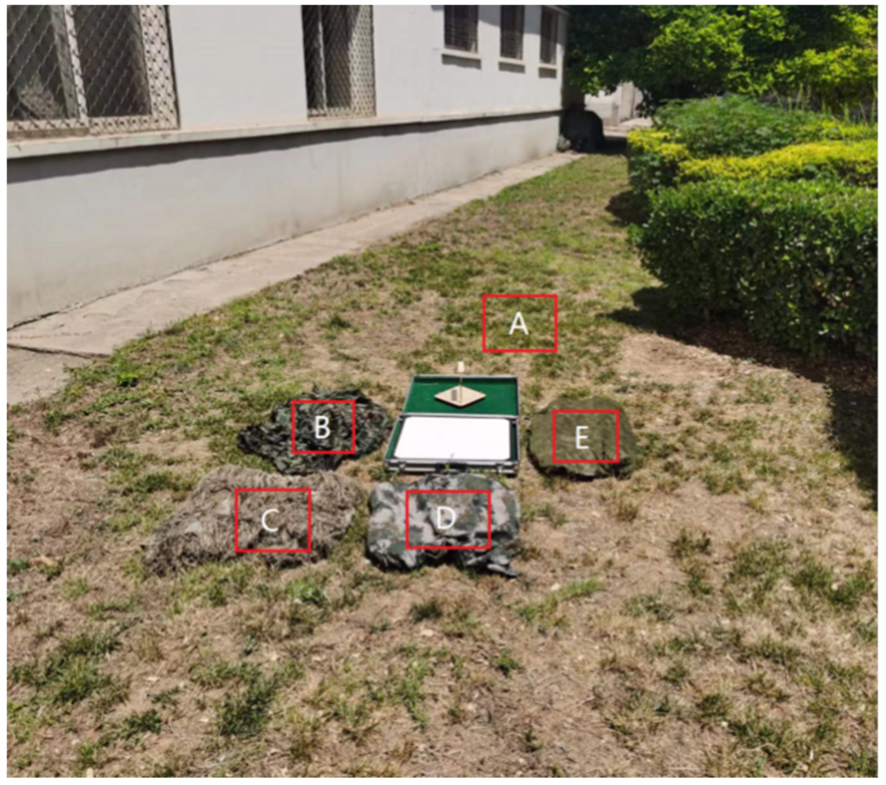
Experiment 1 mainly verified the camouflage ability of different camouflage clothing under visible light/near-infrared hyperspectral images. During the experiment, four types of common camouflage clothing were selected as targets, and the grass was used as the background. The placement position of experimental targets is shown in the Figure 2.
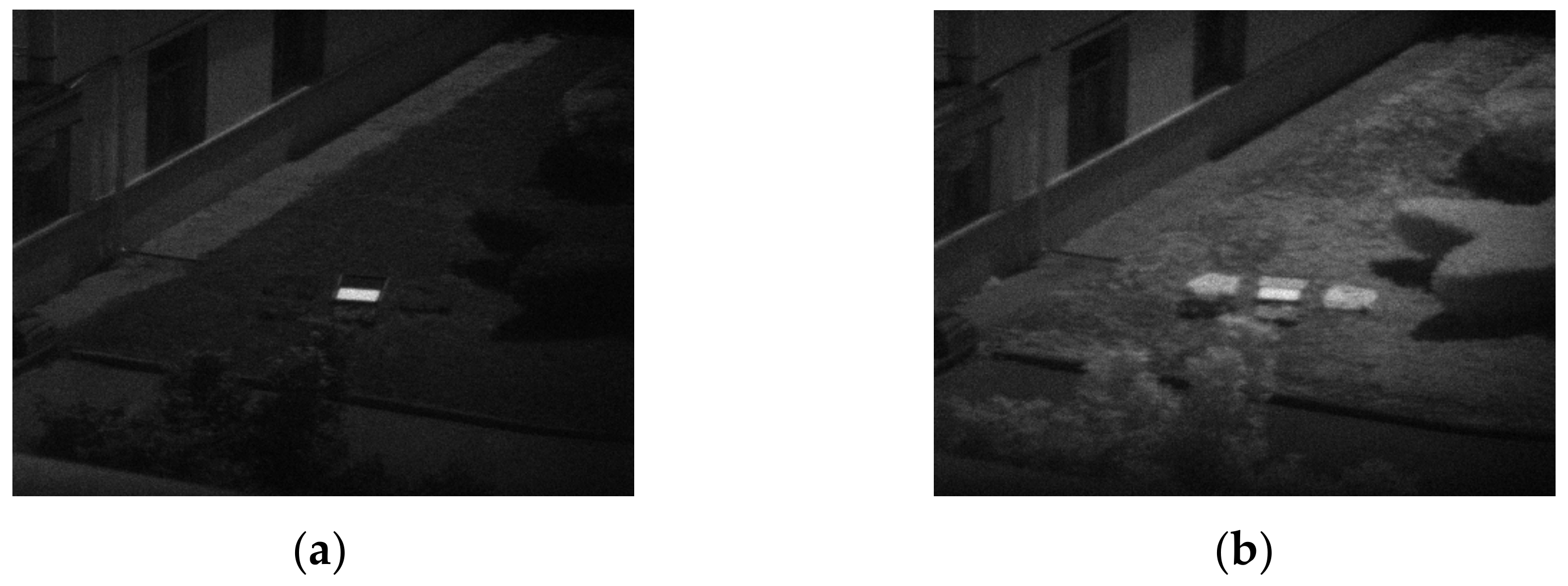
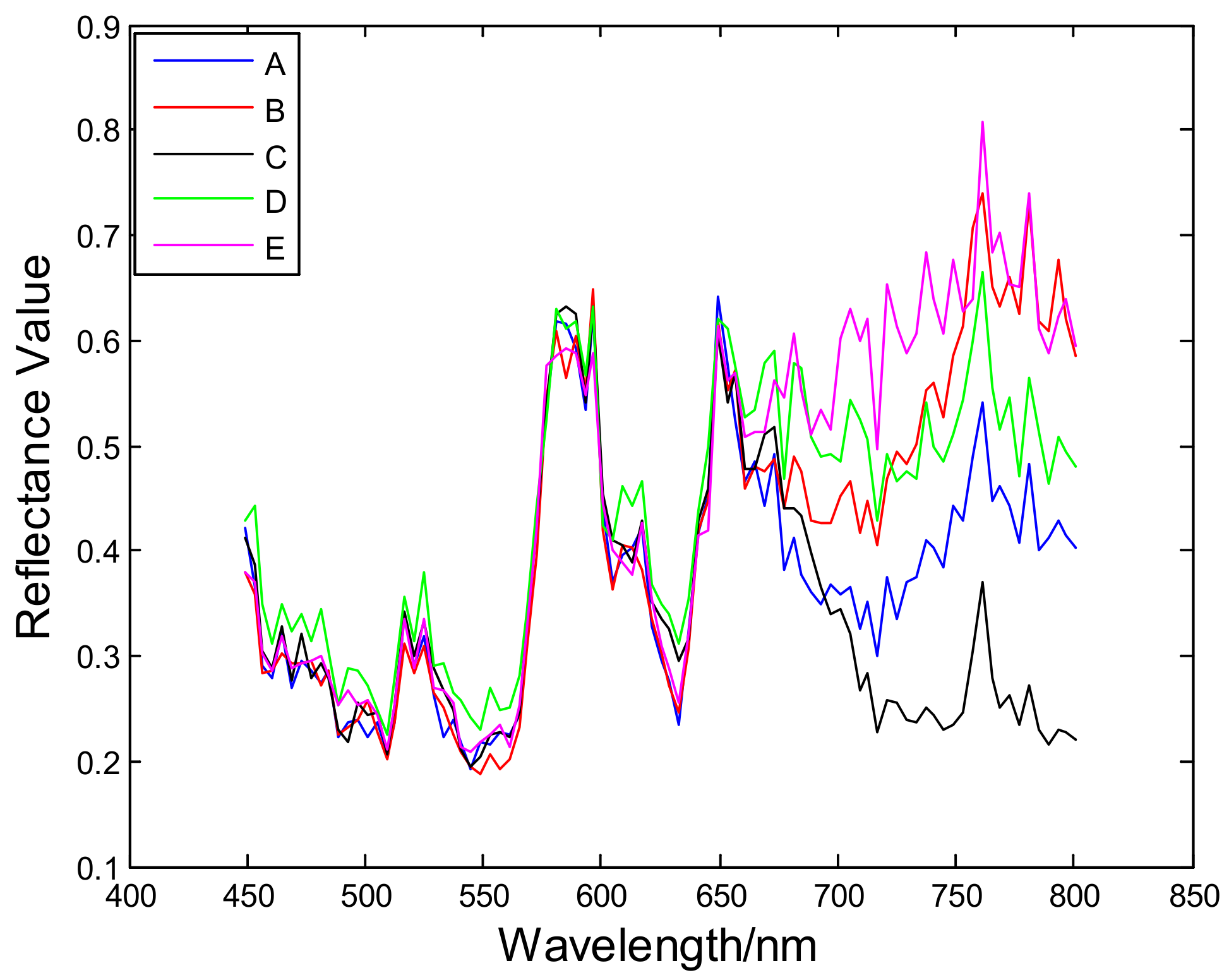
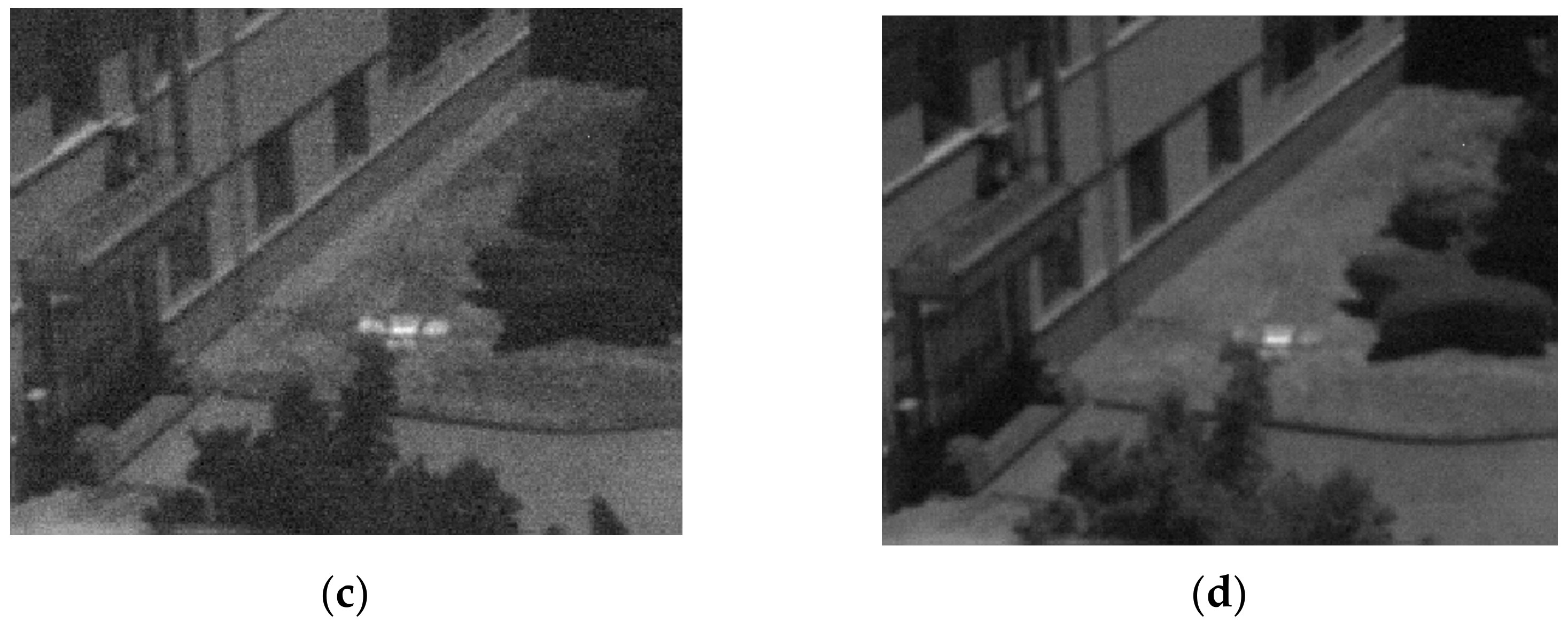
In Figure 2, A is grassland; B, C, D and E are common grass camouflage clothes. Due to the different types of grassland in different regions, the types of camouflage clothing are also varied. The grayscale images of single band images at 553 nm and 801 nm during the experimental shooting are shown in Figure 3. It is possible to select a uniform sub region in the figure target, and use Equation (1) to calculate the spectral characteristic curves of different figures, as shown in Figure 4.
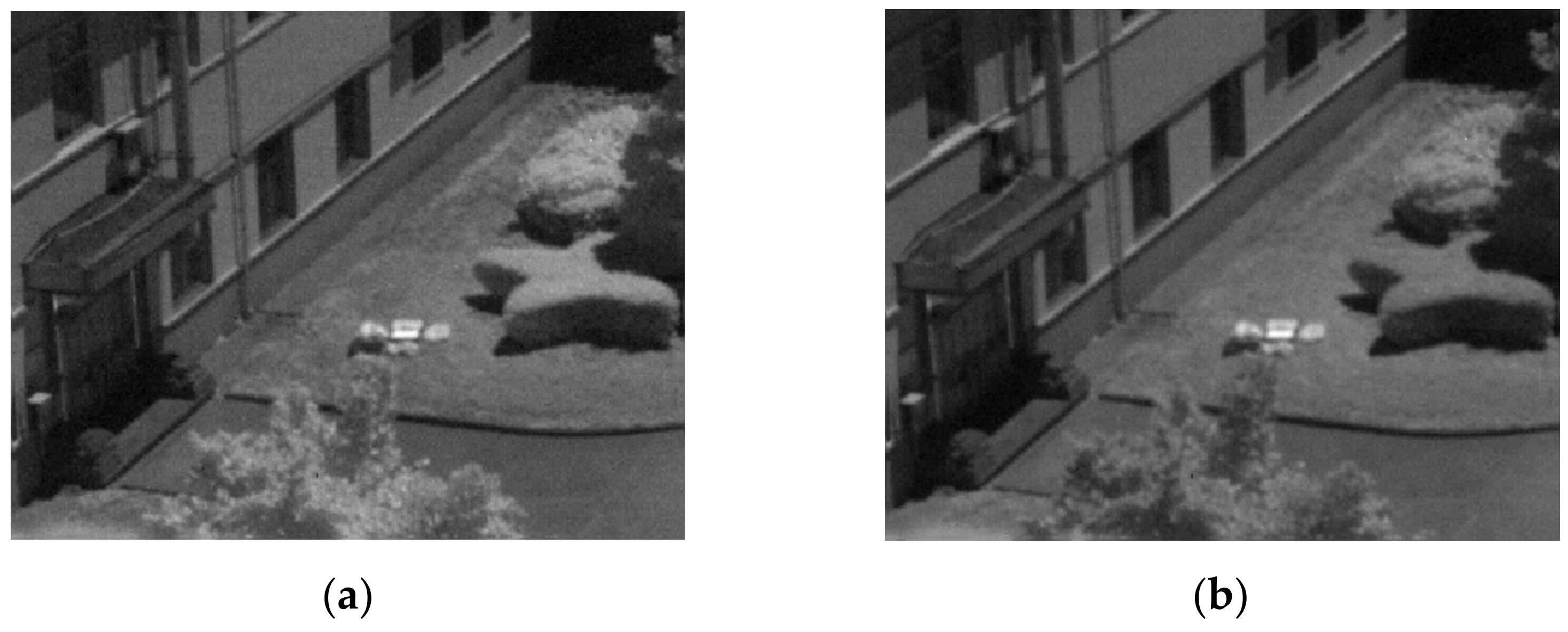
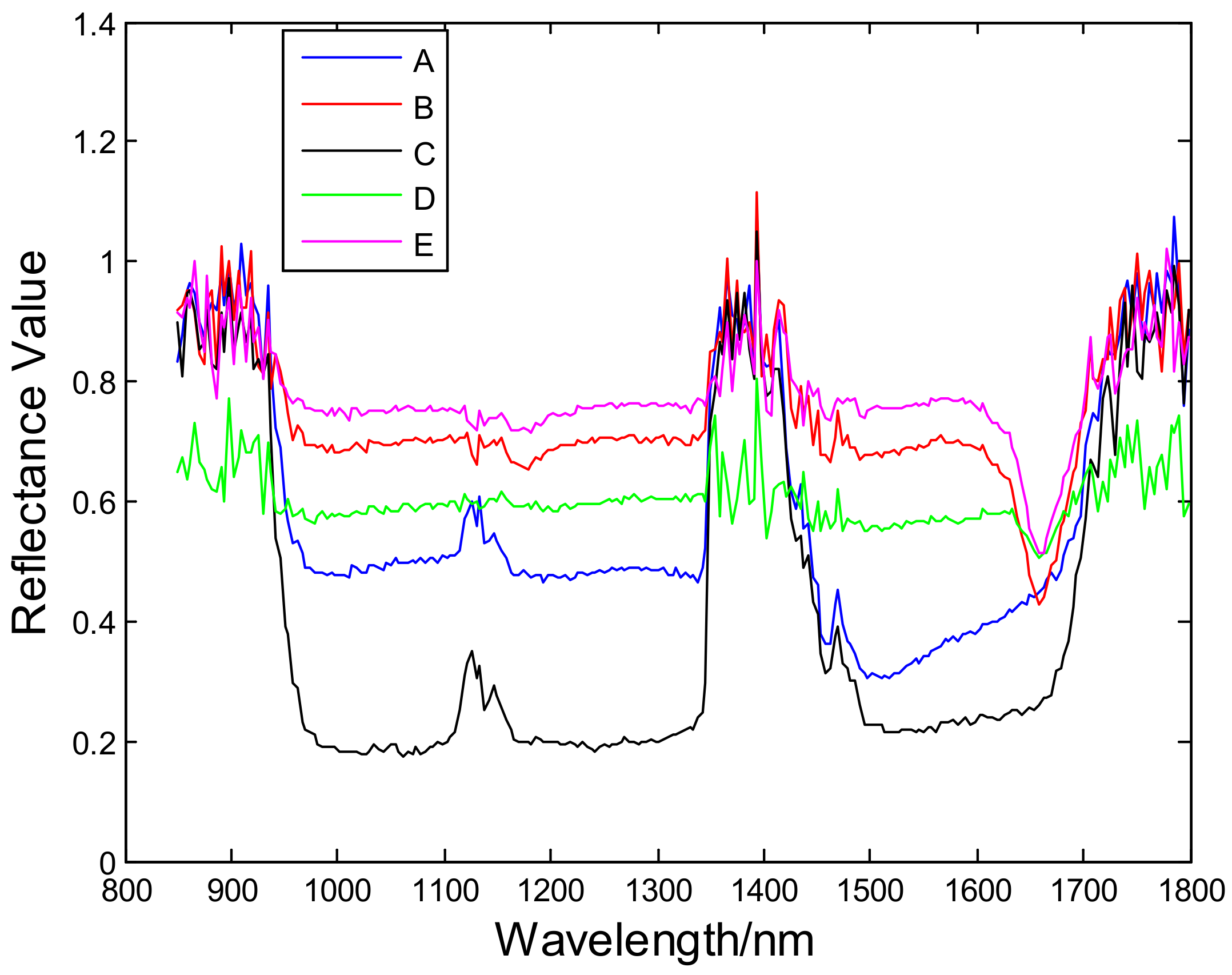
The grayscale images of different wavebands obtained by near-infrared imaging spectrometer are shown in Figure 5, below, and the spectral reflectance curves of different ground objects are shown in Figure 6.

3.2.2. Result Analysis of Experiment 1

The key to using spectral information to identify camouflage is spectral similarity measurement. Common spectral similarity measurement methods mainly include: similarity evaluation based on spectral distance, similarity evaluation based on spectral generalized included angle, and spectral similarity evaluation based on correlation coefficient. The higher the spectral similarity, the better the spectral camouflage effect. The spectral similarity evaluation index used in the experiment consists of spectral angle mapping (SAM) [17], standard deviation (StDev) [18] and correlation coefficient (CC) [19]. SAM characterizes the spectral similarity by calculating the generalized angle θ between two spectral vectors; StDev method characterizes the spectral similarity by using the numerical deviation of two spectral vectors, which is commonly expressed as S . The correlation coefficient can reflect the relationship between two variables and their correlation direction. When the correlation coefficient is -1, it means that there is a complete negative correlation, indicating that the direction and amplitude of change in the two variables to be observed are completely opposite. When the correlation coefficient is +1, it indicates complete positive correlation, indicating that the change direction and change amplitude of the two variables to be observed are identical. When the correlation coefficient is 0, it means that they are not related. See Equations (2)–(4) for details. The two spectral reflectance vectors are X and Y .
θ = arc cos i = 1 n x i y i i = 1 n x i 2 i = 1 n y i 2
where θ is the generalized included angle of two variables. The smaller θ it is, the higher the similarity of spectral curve shape is, the better the camouflage effect is. n represents the spectral dimension.
S = 1 n 1 i = 1 n x i y i 2
where S is the generalized included angle of two variables. The smaller S is, the higher the numerical similarity of the spectral curve is, the better the camouflage effect is. n represents the spectral dimension.
r = i = 1 n x i x ¯ y i y ¯ i = 1 n x i x ¯ 2 × y i y ¯ 2
The correlation coefficient of two variables X and Y is often expressed by r . The greater the correlation r , the stronger the correlation.
In order to obtain the real spectral data of objects, it is necessary to remove the noise band under the influence of the atmosphere. In the near-infrared band, due to the high spectral absorption, the band with large noise impact is removed. Therefore, only 950–1350 nm and 1450–1698 nm are considered in the near-infrared band. The comparison of spectral similarity between visible and near-infrared bands is shown in Table 1 and Table 2 below.
Based on the above experiments, the following conclusions can be drawn:
(1)
According to the comparison between the spectral reflectance curve and the similarity of A, B, C, D and E in the visible light band, it can be seen that before 680 nm, the spectral curves of A, B, C, D and E are basically coincident, and the spectral similarity is high, so it is impossible to distinguish the types of objects; from 680 nm to 801 nm, the spectral curves of A, B, C, D and E are gradually different, and the spectral reflectance of B, D, E, three camouflage suits, is higher than that of grass. For C, the spectral reflectance of camouflage clothing is lower than that of grass. The three evaluation methods can reflect more obvious spectral differences. Therefore, the visible light band is the band range after 680 nm to effectively identify camouflage.
(2)
According to the spectral reflectance curve and similarity comparison of A, B, C, D and E in the near-infrared band, it can be seen that after removing the band with serious noise, the difference of spectral reflectance between camouflage clothing and grass is more obvious than that in visible light band. Therefore, near-infrared spectroscopy can effectively identify the camouflage of the camouflage clothing, excluding the band affected by atmospheric absorption.
(3)
From the perspective of the camouflage effect of different camouflage clothing, in the visible light band, the camouflage effect of D camouflage clothing is the best, and that of C camouflage clothing is the worst; in the near infrared band, compared with other types of camouflage clothing, the camouflage effect of D camouflage clothing is also relatively good. Therefore, in general, D camouflage suit is most suitable for camouflage on grass background.
(4)
From the perspective of similarity evaluation method, SAM and StDev can better reflect the spectral characteristics of camouflage than the CC method. This is because CC only judges the similarity through the spectral change trend and does not take too much account of the difference in spectral reflectance values.

3.3. Experiment 2

3.3.1. Experimental Process

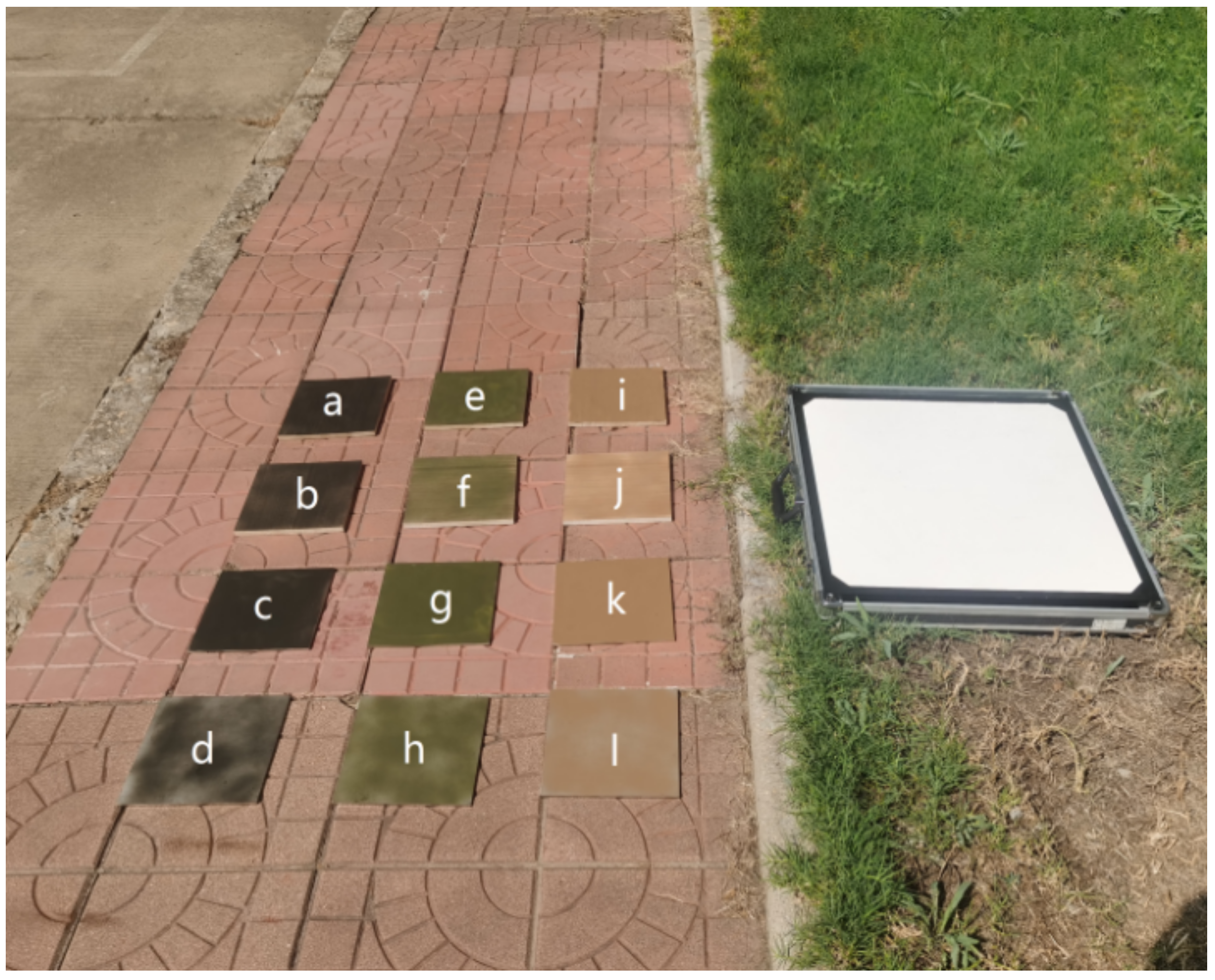
Experiment 2 mainly verified the camouflage ability of different types of camouflage paint under visible light/near-infrared hyperspectral images. During the experiment, three types of common camouflage paint were selected as the research objects, and wood and steel plates were used as the materials under the paint. The placement position of experimental targets is shown in the Figure 7.
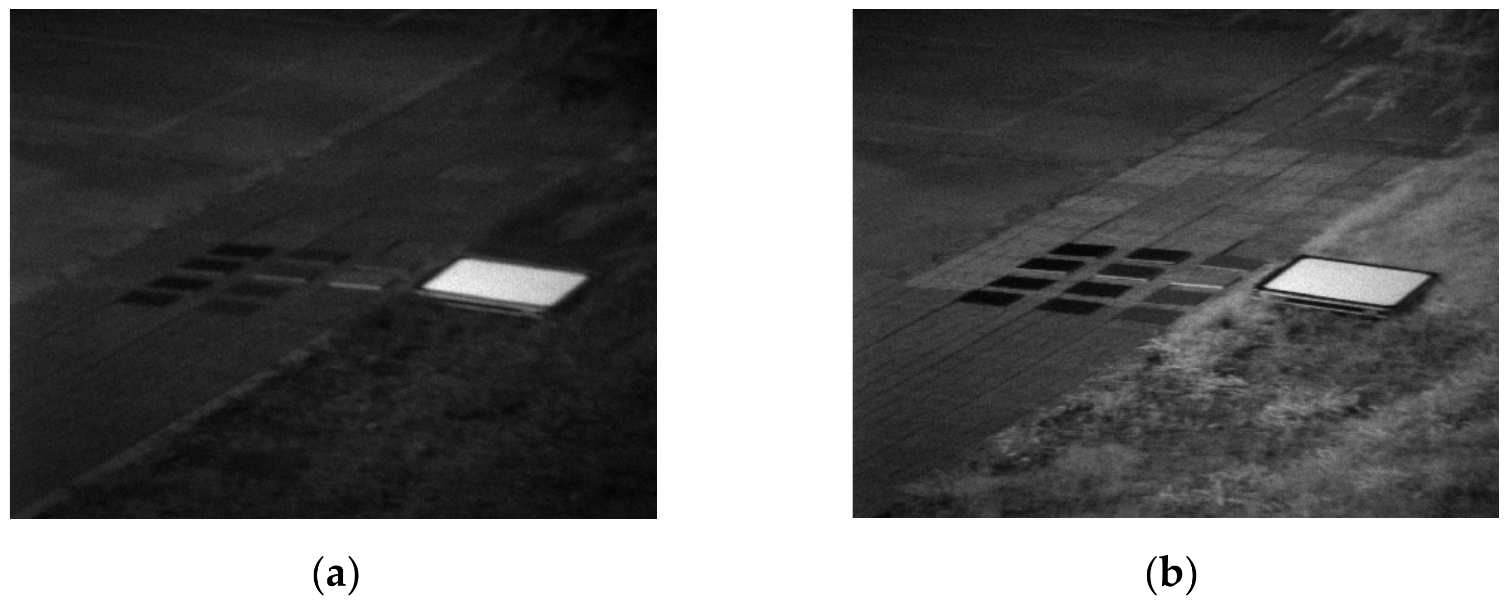
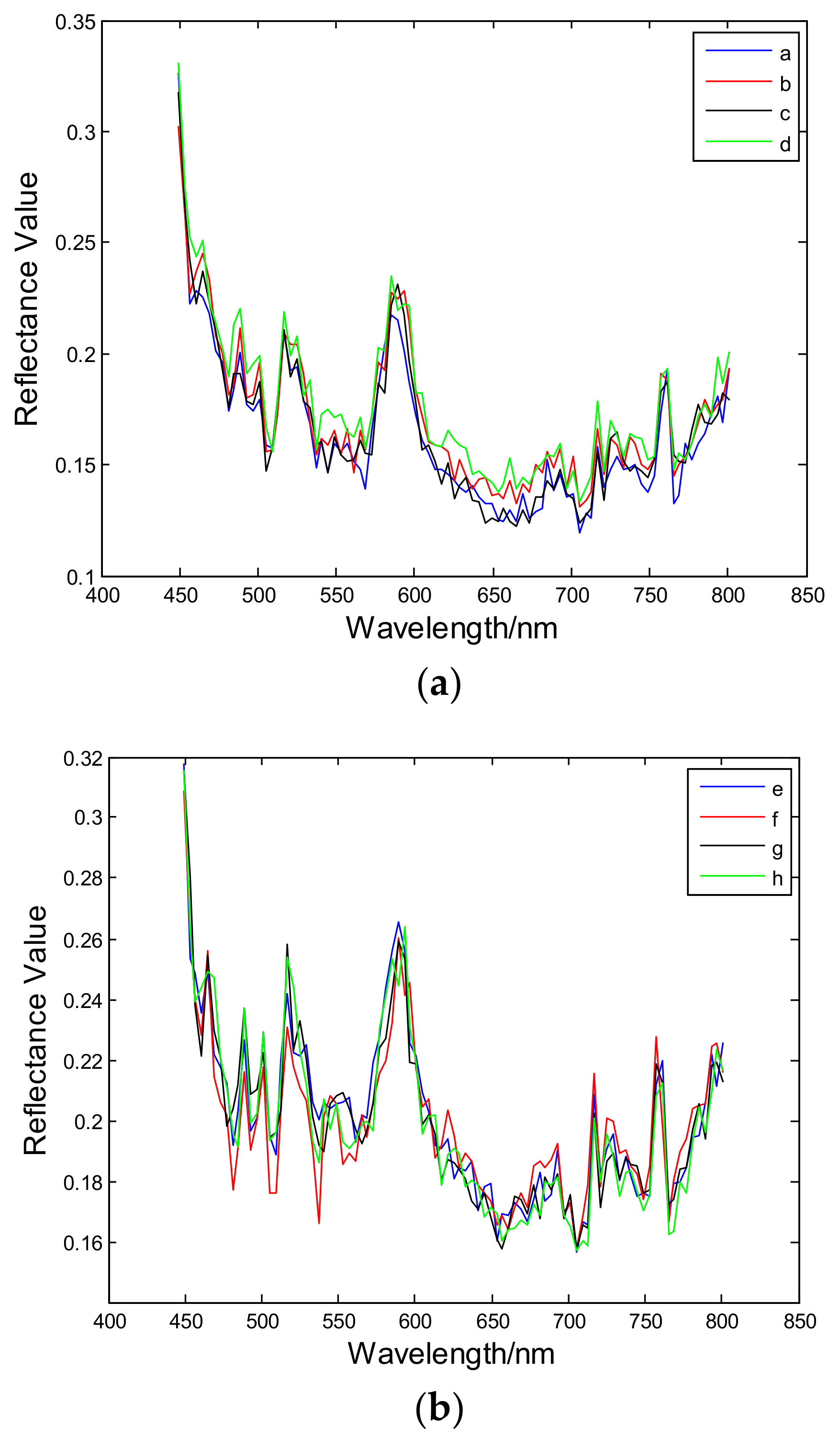
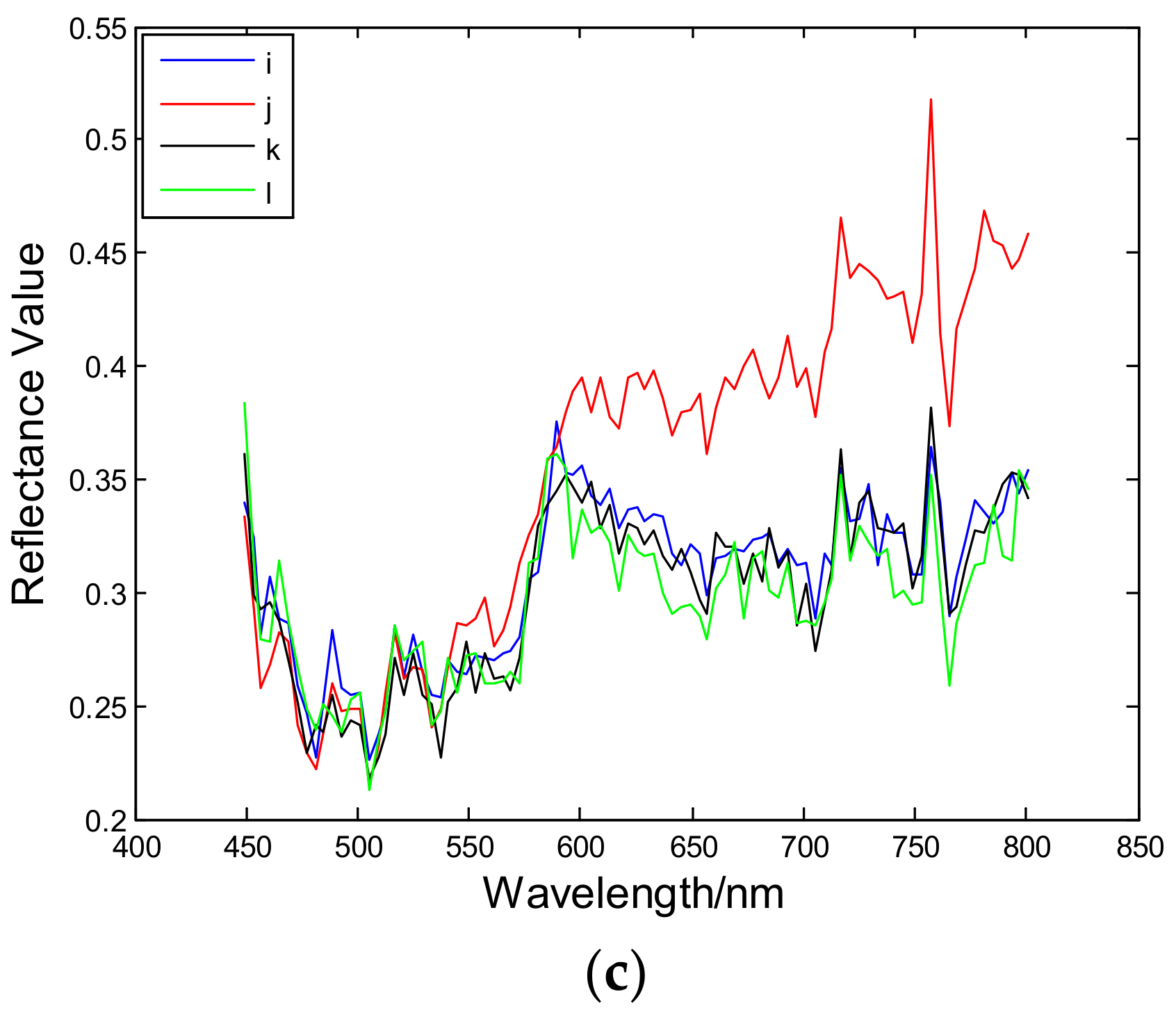
In Figure 7, a–d is dark green camouflage paint; e–h is military green camouflage paint; i–l is desert camouflage paint. a, e, i, c, g, k are dark colors; b, f, j, d, h, l are light colors. The upper six square plates are made of wood and the lower six square plates are made of steel. The camouflage effect of camouflage paint under different wave bands can be verified by comparing different materials with the same paint color. The grayscale images of single band images at 553 nm and 801 nm during the experimental shooting are shown in Figure 8. It is possible to select a uniform sub region in the figure target and use Equation (1) to calculate the spectral characteristic curves of different figures, as shown in Figure 9.
The grayscale images of different wavebands obtained by near-infrared imaging spectrometer are shown in Figure 10, below, and the spectral reflectance curves of different ground objects are shown in Figure 11.

3.3.2. Result Analysis of Experiment 2

The spectral similarity of the target under the same paint spraying was analyzed. Similarly, only 950–1350 nm and 1450–1698 nm were considered in the near-infrared band. The comparison of spectral similarity between visible and near-infrared bands is shown in Table 3 and Table 4, below.
Based on the above experiments, the following conclusions can be drawn:
(1)
According to the comparison of the spectral reflectance curve and the similarity of a-l in the visible light band, it can be seen that the spectral similarity between the dark green paint and the military green paint is high, and the camouflage effect is good, no matter whether it is on the board or the steel plate, no matter the SAM, StDev or CC evaluation method; only light desert paint has poor camouflage effect on the board. Therefore, visible light band has poor effect and stability in identifying camouflage methods of surface painting.
(2)
According to the spectral reflectance curve and similarity comparison of a-l in the near-infrared band, it can be seen that after removing the band with serious noise, the dark green paint camouflage still cannot be recognized in the near-infrared band, and has no recognition effect. However, the light military green paint on the board shows different spectral characteristics. Contrary to the visible light band, it can be recognized in the near-infrared band. The camouflage level of the light desert paint on the board is worse in the near-infrared band, and it can still be recognized. Therefore, the reconnaissance effect of near-infrared spectroscopy in identifying camouflage paint is not obvious.
(3)
From the perspective of the camouflage effect of different spray paint, dark green spray paint has the best camouflage effect, which can effectively play the role of camouflage in the visible and near-infrared bands; the second is the military green paint. Although the military green paint can cover the material of the object under the paint in the visible light band, the camouflage effect is not stable under near-infrared hyperspectral detection. The last is desert paint, which may break through its camouflage in both visible and near-infrared bands, with poor overall effect.

4. Discussion and Conclusions

Visible and near-infrared bands are the most commonly used bands in optical reconnaissance. However, the ability of visible and near-infrared hyperspectral images to recognize camouflage remains uncertain. In this paper, two experiments were conducted to study the ability of visible and near-infrared hyperspectral images to recognize different types of camouflage. In Experiment 1, the camouflage can be better recognized after 680 nm in the visible light band, and there is obvious spectral difference in the near-infrared band; in Experiment 2, camouflage cannot be effectively identified in visible and near-infrared bands, which indicates that “painting camouflage” can avoid visible and near-infrared bands. Through the analysis and thinking of the experimental research and conclusions, this paper proposes the following prospects: (1) In terms of camouflage materials, the current camouflage materials cannot meet the requirements of visible light, near-infrared and other multi band compatible stealth, so the research and development of new spectral camouflage materials is an urgent problem to be solved. (2) In terms of imaging level, the development of near-infrared hyperspectral imaging technology is not yet mature, and the key lies in the limitation of near-infrared detectors. Therefore, it is necessary to develop near infrared detectors with wide band and high resolution. (3) In terms of reconnaissance methods, it can be seen from the experiment that a single reconnaissance method cannot meet the needs of war. Therefore, multi-band hyperspectral reconnaissance, infrared reconnaissance, radar detection and reconnaissance and other reconnaissance methods should be organically combined to achieve the goal of detecting various types of camouflage.

Author Contributions

Data curation, Q.C.; Investigation, B.Z., G.W. and J.L.; Methodology, J.Z., B.Z. and J.Y.; Project administration, J.Y. and Q.C.; Resources, G.W.; Software, J.Z.; Supervision, J.L.; Validation, G.W.; Visualization, B.Z.; Writing—original draft, J.Z.; Writing—review and editing, B.Z. All authors have read and agreed to the published version of the manuscript.

Funding

This research received no external funding.

Institutional Review Board Statement

Not applicable. This article does not involve human or animal research.

Informed Consent Statement

Not applicable.

Data Availability Statement

The data set was obtained by the author and related personnel through the joint experiment with the field imaging spectrometer. The data belong to the Department of Electronic and Optical Engineering of the Army University of Engineering, not a public dataset. The data are not made public due to copyright issues.

Conflicts of Interest

The authors declare no conflict of interest. The funders had no role in the design of the study; in the collection, analyses, or interpretation of data; in the writing of the manuscript, or in the decision to publish the results.

References

  1. Jiang, H.; Hu, Y.; Jiang, X.; Zhou, H. Maturity Stage Discrimination of Camellia oleifera Fruit Using Visible and Near-Infrared Hyperspectral Imaging. Molecules 2022, 27, 6318. [Google Scholar] [CrossRef] [PubMed]
  2. Guan, R.; Li, Z.; Li, T.; Li, X.; Yang, J.; Chen, W. Classification of Heterogeneous Mining Areas Based on ResCapsNet and Gaofen-5 Imagery. Remote Sens. 2022, 14, 3216. [Google Scholar] [CrossRef]
  3. Mukundan, A.; Huang, C.-C.; Men, T.-C.; Lin, F.-C.; Wang, H.-C. Air Pollution Detection Using a Novel Snap-Shot Hyperspectral Imaging Technique. Sensors 2022, 22, 6231. [Google Scholar] [CrossRef] [PubMed]
  4. Mruthyunjaya, P.; Shetty, A.; Umesh, P.; Gomez, C. Impact of Atmospheric Correction Methods Parametrization on Soil Organic Carbon Estimation Based on Hyperion Hyperspectral Data. Remote Sens. 2022, 14, 5117. [Google Scholar] [CrossRef]
  5. Zhang, D.; Zeng, S.; He, W. Selection and Quantification of Best Water Quality Indicators Using UAV-Mounted Hyperspectral Data: A Case Focusing on a Local River Network in Suzhou City, China. Sustainability 2022, 14, 16226. [Google Scholar] [CrossRef]
  6. Sahachairungrueng, W.; Meechan, C.; Veerachat, N.; Thompson, A.K.; Teerachaichayut, S. Assessing the Levels of Robusta and Arabica in Roasted Ground Coffee Using NIR Hyperspectral Imaging and FTIR Spectroscopy. Foods 2022, 11, 3122. [Google Scholar] [CrossRef] [PubMed]
  7. Li, N.; Pan, X.; Yang, L.; Huang, Z.; Wu, Z.; Zheng, G. Adaptive CFAR Method for SAR Ship Detection Using Intensity and Texture Feature Fusion Attention Contrast Mechanism. Sensors 2022, 22, 8116. [Google Scholar] [CrossRef] [PubMed]
  8. Mantau, A.J.; Widayat, I.W.; Leu, J.-S.; Köppen, M. A Human-Detection Method Based on YOLOv5 and Transfer Learning Using Thermal Image Data from UAV Perspective for Surveillance System. Drones 2022, 6, 290. [Google Scholar] [CrossRef]
  9. Jian, B.-L.; Peng, C.-C. Development of an Automatic Testing Platform for Aviator’s Night Vision Goggle Honeycomb Defect Inspection. Sensors 2017, 17, 1403. [Google Scholar] [CrossRef] [PubMed] [Green Version]
  10. Hupel, T.; Stütz, P. Adopting Hyperspectral Anomaly Detection for Near Real-Time Camouflage Detection in Multispectral Imagery. Remote Sens. 2022, 14, 3755. [Google Scholar] [CrossRef]
  11. Lu, Q.; Li, M.; Tian, A. Green Plant Leaf-inspired Smart Camouflage Fabrics for Visible Light and Near-infrared Stealth. J. Bionic Eng. 2022, 19, 788–798. [Google Scholar]
  12. Zhao, J.; Zhou, B.; Wang, G.; Liu, J.; Ying, J. Camouflage Target Recognition Based on Dimension Reduction Analysis of Hyperspectral Image Regions. Photonics 2022, 9, 640. [Google Scholar] [CrossRef]
  13. Shi, G.; Huang, H.; Liu, J.; Li, Z.; Wang, L. Spatial-Spectral Multiple Manifold Discriminant Analysis for Dimensionality Reduction of Hyperspectral Imagery. Remote Sens. 2019, 11, 2414. [Google Scholar] [CrossRef] [Green Version]
  14. Ettabaa, K.S.; Salem, M.B. Adaptive progressive band selection for dimensionality reduction in hyperspectral images. J. Indian Soc. Remote Sens. 2018, 46, 157–167. [Google Scholar]
  15. Khan, M.J.; Khan, H.S.; Yousaf, A.; Khurshid, K.; Abbas, A. Modern trends in hyperspectral image analysis: A review. IEEE Access 2018, 6, 14118–14129. [Google Scholar] [CrossRef]
  16. Wise, J.E.; Mars, J.C. Field Reflectance Measurements at Night of Beach and Desert Sands within a Particulate BRDF Model. Remote Sens. 2022, 14, 5020. [Google Scholar] [CrossRef]
  17. Park, J.; Jeong, J.; Park, Y. Ship Trajectory Prediction Based on Bi-LSTM Using Spectral-Clustered AIS Data. J. Mar. Sci. Eng. 2021, 9, 1037. [Google Scholar] [CrossRef]
  18. Yadav, S.; Yoneda, M.; Susaki, J.; Tamura, M.; Ishikawa, K.; Yamashiki, Y. A Satellite-Based Assessment of the Distribution and Biomass of Submerged Aquatic Vegetation in the Optically Shallow Basin of Lake Biwa. Remote Sens. 2017, 9, 966. [Google Scholar] [CrossRef] [Green Version]
  19. Espinoza, C.Z.; Khot, L.R.; Sankaran, S.; Jacoby, P.W. High Resolution Multispectral and Thermal Remote Sensing-Based Water Stress Assessment in Subsurface Irrigated Grapevines. Remote Sens. 2017, 9, 961. [Google Scholar] [CrossRef]
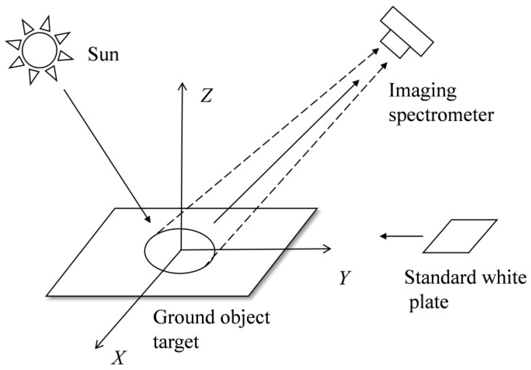
Figure 1. Acquisition of target spectral reflectance by field measurement.
Photonics 09 00957 g001
Figure 2. Relative position of the targets in Experiment 1.
Photonics 09 00957 g002
Figure 3. Single band grayscale images at different wavelengths. (a) Single band grayscale images at 553 nm. (b) Single band grayscale images at 801 nm.
Photonics 09 00957 g003
Figure 4. Spectral reflectance of A, B, C, D, E in visible light band.
Photonics 09 00957 g004
Figure 5. Single band grayscale images at different wavelengths. (a) Single band grayscale images at 1050 nm. (b) Single band grayscale images at 1250 nm. (c) Single band grayscale at 1570 nm. (d) Single band grayscale at 1650 nm.
Photonics 09 00957 g005aPhotonics 09 00957 g005b
Figure 6. Spectral reflectance of A, B, C, D, E in near-infrared band.
Photonics 09 00957 g006
Figure 7. Relative position of the target in Experiment 2.
Photonics 09 00957 g007
Figure 8. Single band grayscale images at different wavelengths. (a) Single band grayscale images at 553 nm. (b) Single band grayscale images at 801 nm.
Photonics 09 00957 g008
Figure 9. Spectral reflectance of target in visible light band. (a) Spectral reflectance of a–d. (b) Spectral reflectance of e–h. (c) Spectral reflectance of i–l.
Photonics 09 00957 g009aPhotonics 09 00957 g009b
Figure 10. Single band grayscale images at different wavelengths. (a) Single band grayscale images at 1050 nm. (b) Single band grayscale images at 1250 nm. (c) Single band grayscale at 1570 nm. (d) Single band grayscale at 1650 nm.
Photonics 09 00957 g010
Figure 11. Spectral reflectance of target in near-infrared band. (a) Spectral reflectance of a–d. (b) Spectral reflectance of e–h. (c) Spectral reflectance of i–l.
Photonics 09 00957 g011
Table 1. Comparison of Spectral Similarity in Visible Light Band.
Wavelength Range Evaluation MethodBCDE
449–801 nmASAM0.17890.22170.11440.2190
StDev0.09670.08790.08130.1361
CC0.9673085730970809733
449–681 nmASAM0.06100.05520.08810.1015
StDev0.02320.02420.05210.0417
CC0.93930.85790.93890.9631
681–801 nmASAM0.07800.24270.08920.0772
StDev0.16530.14930.12090.2297
CC0.85750.87900.83510.8197
Table 2. Comparison of Spectral Similarity in Near Infrared Band.
Wavelength Range Evaluation MethodBCDE
950–1350 nmASAM0.06330.22390.07110.0784
StDev0.20230.28310.10150.2562
CC0.99700.98130.99790.9974
1450–1698 nmASAM0.2478015710.16380.2423
StDev0.28740.13170.18670.3516
CC0.88920.97190.96070.9009
Table 3. Comparison of Spectral Similarity in Visible Light Band.
Wavelength RangeEvaluation Methoda–cb–de–gf–hi–kj–l
449–801 nmSAM0.04770.03990.04080.05950.03740.1447
StDev0.00830.00920.00840.01200.01280.0815
CC0.98660.962509746098740.97040.9107
Table 4. Comparison of Spectral Similarity in Near Infrared Band.
Wavelength RangeEvaluation Methoda–cb–de–gf–hi–kj–l
950–1350 nmSAM0.07440.04830.10580.22830.04880.0864
StDev0.00540.01260.00920.12100.00950.2831
CC0.97010.9880.97350.9451096570.9742
1450–1698 nmSAM0.03680.04040.13680.12800.03540.0738
StDev0.01040.01500.02800.13480.01270.2687
CC0.99370.98600.98290.99230.976509936
Publisher’s Note: MDPI stays neutral with regard to jurisdictional claims in published maps and institutional affiliations.