Article

Accurate Passive 3D Polarization Face Reconstruction under Complex Conditions Assisted with Deep Learning

1
School of Optoelectronic Engineering, Xidian University, Xi’an 710071, China
2
Xi’an Key Laboratory of Computational Imaging, Xi’an 710071, China
3
Hangzhou Institute of Technology, Xidian University, Hangzhou 311231, China
4
Science and Technology on Electro-Optical Information Security Control Laboratory, Tianjin 300308, China
*
Author to whom correspondence should be addressed.
Photonics 2022, 9(12), 924; https://doi.org/10.3390/photonics9120924
Submission received: 31 August 2022 / Revised: 4 November 2022 / Accepted: 21 November 2022 / Published: 30 November 2022
(This article belongs to the Special Issue Advanced Polarimetry and Polarimetric Imaging)

Abstract

:
Accurate passive 3D face reconstruction is of great importance with various potential applications. Three-dimensional polarization face reconstruction is a promising approach, but one bothered by serious deformations caused by an ambiguous surface normal. In this study, we propose a learning-based method for passive 3D polarization face reconstruction. It first calculates the surface normal of each microfacet at a pixel level based on the polarization of diffusely reflected light on the face, where no auxiliary equipment, including artificial illumination, is required. Then, the CNN-based 3DMM (convolutional neural network; 3D morphable model) generates a rough depth map of the face with the directly captured polarization image. The map works as an extra constraint to correct the ambiguous surface normal obtained from polarization. An accurate surface normal finally allows for an accurate 3D face reconstruction. Experiments in both indoor and outdoor conditions demonstrate that accurate 3D faces can be well-reconstructed. Moreover, with no auxiliary equipment required, the method ensures a total passive 3D face reconstruction.

1. Introduction

With the rapid development of visual technology, 3D face reconstruction has extended many applications, including security authentication [1], face media manipulation [2,3] and face animation [4,5]. Generally speaking, 3D face reconstruction can be categorized into three groups: software-based, hardware-based and image-based [6]. Software-based methods usually employ 3D processing software to establish a face model. Examples include 3DS MAX, Maya, Unity 3D, etc. Hardware-based methods usually adopt a specialized projector or laser to obtain the face shape in a noncontact way. For example, LiDAR (light detection and ranging) derives 3D shapes by detecting the time difference of reflected lasers. It has the advantages of high precision and a long detection distance, but costs a lot and has a hidden danger to the eyes. Three-dimensional imaging with structured light can also enable high-precision shape recovery. However, multicolored object reconstruction is a big challenge due to dependence on striped light. Image-based methods use one or more pictures to build a 3D face shape based on computer vision models. Examples include methods based on Lambert, Phong, Cook–Torrance, etc. [7]. Image-based methods using only one or more pictures have the advantages of a low cost and simple operation, but also cannot guarantee high accuracy due to limited input data. Compared to active 3D reconstruction methods, passive shape recovery has more potential applications. For example, binocular stereo vision mimics how our eyes perceive 3D information using two cameras. However, the reconstruction accuracy highly depends on the base line, leading to an accuracy decline along with increasing detection distance.
Polarization provides another possibility for high-precision passive 3D face reconstruction. In 1979, K. Koshikawa initiated a 3D shape recovery utilizing polarization. The quantitative characterization relationship between the polarization characteristic of reflected light and the zenith of an object’s surface normal was established via the illumination of active lighting sources [8]. Since then, 3D polarization imaging has been widely studied. In 1988, L. B. Wolff established a model that used the reflected light of an object’s surface to calculate 3D information for the first time [9]. This provided an essential theoretical foundation for 3D polarization imaging technology. In 1999, O. Drbohlav et al. used the polarization characteristic of diffuse reflected light to reconstruct objects’ 3D shapes, together with the SFS (shape from shading) method [10]. In 2006, G. A. Atkinson et al. concluded that using the polarization characteristic of diffuse reflected light could solely determining the zenith [11]. Furthermore, K. P. Gurton accomplished 3D polarization facial reconstruction in the long-wave infrared band using the polarization characteristic of diffuse reflected light [12]. Subsequently, A. Kadambi et al. proved the feasibility of passive 3D polarization imaging technology based on experimental data. The 3D polarization imaging system of natural illumination was verified in accordance with the rough depth map obtained using ToF [13]. Y. Ba et al. utilized deep learning to directly estimate the surface normal and further recover 3D shapes [14]. P. Gotardo et al. employed a subset of cross-polarized and parallel-polarized cameras for the illumination in combination with photogrammetry systems. Very favorable results were obtained [15,16]. Although much progress has been accomplished in 3D polarization imaging, the imaging method resorting to auxiliary equipment failed to substantially achieve a major breakthrough on accurate passive 3D face reconstruction. Major limitations exist, especially for complex ambient light under natural illumination.
In this study, an accurate passive 3D polarization face reconstruction method is proposed, assisted with deep learning. By first capturing polarization images, the normal of each microfacet on a pixel level can then be solved based upon the polarization characteristic of diffusely reflected light from the target surface. Instead of directly reconstructing a 3D face, a CNN-based 3DMM (3D morphable model) is adopted here in response to the ambiguous normal. It provides conditional constraints to determine an accurate unique normal and avoid further distortions. Then, an accurate 3D face can be reconstructed. It attained a breakthrough in passively reconstructing 3D faces, even at a long detection distance under natural conditions. Detailed models are introduced in Section 2 and experiments and results are shown in Section 3.

2. Models

Figure 1 illustrates the overall schematic of the proposed passive 3D polarization face reconstruction method. By introducing a CNN-based 3DMM into the imaging process, the azimuth ambiguity, the major problem of 3D polarization imaging, can be amended without auxiliary equipment. We detail the models as follows:

2.1. Normal Estimation from Polarization

The normal vector n of a microfacet on an object’s surface is constrained by two parameters: the zenith θ and the azimuth φ [17]. Fresnel’s formula provides a relation between the normal vector and the polarization information of the reflected light as shown through Equation (1)
p = ( n 1 n ) 2 sin 2 θ 2 + 2 n 2 ( n + 1 n ) 2 sin 2 θ + 4 cos θ n 2 sin 2 θ
where p is the degree of polarization (DoP), θ is the zenith of the normal of a microfacet and n is the refractive index of the target, typically, n = 1.5 [18]. Then, the zenith θ can be uniquely determined using Equation (1) [19].
Polarization imaging detection usually requires four polarization subplots with a linear polarizer mounted in front the detector [20]. According to Malus’ law, the detected intensity varies as expressed through Equation (2) [21]
I = I max + I min 2 + I max I min 2 cos ( 2 θ p o l 2 ϕ )
where Imax and Imin are the observed maximum and minimum pixel brightness during polarizer rotation and ϕ is the phase of the detected light. For the detected diffuse reflection of every microfacet, the azimuth of the surface normal satisfies φ = ϕ at Imax. According to (2), when θpol = ϕ, I = Imax. We could determine azimuth φ when Imax was generated. However, as Figure 2a shows, Imax would appear at ϕ or ϕ + π, but only one of them would be correct, as Figure 2b illustrates. This is the problem of an ambiguous azimuth, which makes the surface normal uncertain and further deforms the reconstructed 3D face. Figure 3 illustrates the deformation caused by the uncertain normal in face reconstruction from polarization. In the following discussion, we attempted to fix this issue by introducing a CNN into the process and allowing for an accurate 3D face reconstruction.

2.2. Normal Constraint from CNN-Based 3DMM

The major thought for correcting an ambiguous normal is to determine an extra constraint, and, here, we used a CNN-based 3DMM to calculate a rough depth map. The 3DMM is a typical method used to recover a 3D face, including the CNN-based 3DMM and optimization-based 3DMM. In comparison to the optimization-based 3DMM, a CNN-based method enables the avoidance of an ill-posed problem, and is more robust in reconstruction accuracy. It incorporates the feature information extraction of the input face using the convolutional nerve and matching the input facial feature information using the 3DMM method. Therefore, it meets the requirements better than the optimization-based 3DMM in the study. It can avoid potential errors caused by facial expressions and the lack of 3D facial sample data [2]. By introducing factors, including intensity, expression, texture details and illumination into the training network, the rough depth map could be obtained through only one single image.
A training process, as shown in Figure 4, was set up. A 2D image I with no label was input. Then, facial feature points were located and key facial areas were segmented according to facial information in the image. With the feature points inputting into the CNN-based ResNet-50 network model, an initial set of parameters was generated and, further, an initial depth map was obtained. By adjusting the weight coefficients to a minimum loss, the final depth map expressed through Equation (3) was achieved [22]
S = S ( α , β ) = S a v g + B i d α + B exp β T = T ( δ ) = T a v g + B t δ
where Savg and Tavg represent the average facial form and the average facial texture information, respectively; Bid, Bexp and Bt are the principal component analysis (PCA) bases of identity, expression and texture, respectively; and α, β and δ (αR80, βR64 and δR80) are parameters for estimating the 3D target in-depth map [23]. Furthermore, the influences of illumination and facial expression on the result estimation should also be considered and expressed with illumination parameter ϒR9 and the facial expression parameter p.
The unknown parameters could be expressed as a vector x = (α, β, δ, ϒ, p) ∈ R239 [24]. With the given training image I, the parameter x was estimated without labels using ResNet-50 to obtain the initial 3D facial estimation I′. Next, the mixed-level loss (including the pixel level and perception level) in the initial estimation result I′ was evaluated and propagated reversely. Therefore, the iterative corrections of network model parameters could be realized. Furthermore, a multilayer cascaded loss function was constructed to provide reference to the parameter correction against the application scenarios of the face target. This could be expressed as [2]:
L ( x ) = ω p t o L p t o ( x ) + ω f e a L f e a ( x ) + ω p e r L p e r ( x ) + ω c o e f L c o e f ( x ) + ω a l b L a l b ( x )
where Lpto(x), Lfea(x), Lper(x), Lcoef(x) and Lalb(x) indicate the photometric loss, the landmark loss, the perceptual-level loss, the regularization terms and flat constraint penalty function and ω is the corresponding coefficients determined during the training process.
Since changes in appearances, such as glasses, hair, beards or even heavy makeup, are challenging for facial target recognition, the skin color probability Pi was introduced to each pixel in the image in the loss function [22]. Through this, it could prevent the increase in errors caused by the above interferences during the network training [2,3]. Moreover, facial feature classification could be avoided using facial segmentation, thanks to the Bayesian classifier obtained from training. Meanwhile, the reconstruction area concerning the network could focus on the face by overcoming interferences, such as the occlusion of glasses and hair. The photometric loss function of the facial target could be defined as [25,26]
L p t o ( x ) = i A i I i I i ( x ) 2 i A i
where i is the position index of the image pixel, M is the reprojection area of the face target and the L2 norms were solved at the corresponding positions for the input image I and the output image I’. In addition, when Pi > 0.5, Ai = 1; otherwise, Ai = Pi [27]. The loss of pixel intensity information could be estimated in the 2D image.
When processing the loss function of the target feature point, a 3D face alignment should have first been performed. Then, 68 facial feature points {qn} in the facial training image were detected using the A. Bulat method [28]. Moreover, a 2D projection should have been performed on the output data to obtain 68 facial feature points {qn}. This was because {qn} were the 3D data. The loss function between the input and output information could be expressed as [29]:
L f e a ( x ) = 1 N n = 1 N ω n q n q n ( x ) 2
where ωn represents the weight of the target feature point. In general, the weight values of the mouth and nose feature points in the image were set to 20 as a matter of experience, and other feature areas were set to 1 [23]. The introduction of such a loss would raise the smoothness and continuity in various facial areas of the 3DMM.
The local minimum often appeared in the output results of the CNN. This was due to various external factors of changes and disturbances of facial targets, leading to the nonconvergence of the optimization functions [2,3]. In response to this problem, the loss of target perception was added to the model to enhance the network accuracy in facial reconstruction [30]. The cosine distance between the feature points for calculating the loss function shown in Equation (7) was constructed using the extracted depth features of the target image
L p e r ( x ) = 1 < f ( I ) , f ( I ( x ) ) > f ( I ) f ( I ( x ) )
where, f(·) stands for the depth feature coding and <·,·> represents the vector inner product. The overall profile was more consistent with the real situation of the target in terms of intuitive perception. This was achieved upon the introduction of target perception loss into the CNN model.
The target depth map estimated with the network consisted of various discrete points with depth information. Thus, a regularization constraint was added to parameters α, β and δ in Equation (4). This was to prevent the degradation of facial shapes and texture details during the estimation of the depth information of discrete points from the unlabeled dataset. The loss function could be expressed as:
L c o e f ( x ) = ω α α 2 + ω β β 2 + ω γ δ 2
The flat constraint penalty function is usually used to correct color distortions. In this study, real-color images captured by using the polarization image were used. Therefore, Lalb in Equation (4) was ignored.
With the help of the four loss functions and the 3DMM method, given a single target image as the input, the rough depth map could be effectively obtained. Then, high-precision 3D target reconstruction could be implemented by correcting the surface normal calculated based on polarization.
The rough depth map could provide a constraint for the ambiguous normal solved using polarization. The constraint was provided by means of effectively showing the accurate gradient variation trend in microfacets on a target’s surface. Thus, the polarization normal could be corrected using Equation (9):
Λ ^ = arg min Λ G net Λ ( G polar ) 2 2 , Λ = { 0 , 1 }
where Gnet is the normal data obtained from the CNN-based 3DMM Gpolar is the normal data from polarization, Λ ^ is a set of binary operands and Λ is a binary operator. Λ ^ = 1 was assumed to indicate that the estimated azimuth from the polarization was accurate. Conversely, if Λ ^ = 0, the estimated azimuth from the polarization should have been corrected by reversing 180°. The corrected azimuth could be expressed as
φ cor = φ polar + ( 1 Λ ) π
where φpolar is the azimuth directly recovered from polarization and φcor stands for the final accurate azimuth, i.e., the normal of a target’s microfacet could be solely solved.

2.3. Reconstructing 3D Profile

Theoretically, an accurate 3D face could be recovered based on a corrected (θ, ɸ) using integration. However, in some conditions, there are discrete nonintegrable points that can fail the final reconstruction. Here, we reconstructed a 3D face with the help of the Frankot–Chellappa 3D surface restoration functions [31] in Equation (12)
p g = tan θ cos φ q g = tan θ sin φ
z = F 1 { j 2 π u N F { p g } + 2 π v M F { q g } ( 2 π u N ) 2 + ( 2 π v M ) 2 } = F 1 { j 2 π u N F { p g } + v M F { q g } ( u N ) 2 + ( v M ) 2 }
where F{·} and F−1{·} stand for the discrete Fourier transform and inverse transform, respectively, u and v are the frequency in the Fourier domain and M and N are the dimensions of the input images.

3. Experiments and Results Analysis

Relying solely on the CNN-based 3DMM also allowed for 3D face reconstruction. However, two major problems could be encountered, 2D photo misrecognition and inaccurate recovery for Asian people, since training data were based on occidental people. Figure 5 shows an illustration where four targets were used, including a photo of a Chinese man, a Chinese woman wearing no glasses, a Chinese man wearing near-infrared glasses and a plaster statue.
The depth information recovered with the CNN-based 3DMM is shown in the second row in Figure 5, where interferences in the information, such as hair and glasses, were overcome. However, what should be noted is that the 3D information was also recovered from a male photo resulting from the training set input in the CNN-based 3DMM training process. In addition, in the final recovered results in the third row in Figure 5, a significant difference could be noticed between the recovered 3D face and the real face. This was affected by the training set of the CNN-based 3DMM, which was based on occidentals, causing the output result approaching the “average face” as much as possible.
Though the CNN-based 3DMM method was disadvantageous in the two referred aspects, it could assist 3D polarization imaging to recover accurate 3D faces as discussed before. The real surface normal could be directly obtained through 3D polarization imaging, but a constraint from the CNN-based 3DMM method would be required to handle the ambiguous azimuth. Through this, the 3D face could be reconstructed in an accurate manner.
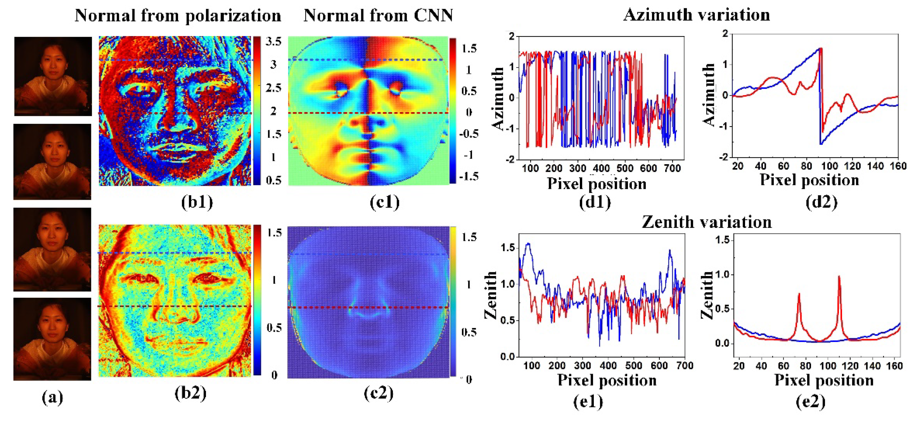
In Figure 6, we illustrated in detail why the normal correction was required and how to correct it with the assistance of the CNN-based 3DMM. Figure 6a shows four intensity images at 0°, 45°, 90° and 135°, directly obtained with the detector. Figure 6b1,b2 are the azimuth φ and the zenith θ from the polarization. Figure 6c1,c2 are φ and θ from the CNN-based 3DMM. In general, the data from the CNN-based 3DMM presented relatively mild variations, indicating possible lost details. We chose two rows of pixels from each angle image in Figure 6b1,b2,c1,c2, and drew up the intensity distribution over the pixel position. Figure 6d1,d2 are azimuth data from the results of the polarization and CNN-based 3DMM, respectively. The curve in Figure 6d1 showed that both statistical curves had no regular changes at zero, which was consistent with the analysis on the azimuth uncertainty problem in 3D polarization imaging. However, the variations indicated that abundant facial details were detected. According to the graph in Figure 6d2, both the blue and red curves were at the pixel value of approximately 90 in the middle of the image, while the azimuth changed from a positive value to a negative value. The curve variation showed that a similar trend on both sides could be witnessed, which was consistent with the variation trend of the real target. The data variation in Figure 6d1,d2 indicate that it was feasible to employ the CNN-based 3DMM to the azimuth from polarization by providing an overall reference and retaining detail information at the same time.
Figure 6e1,e2 display the zenith data from the results of the polarization and CNN-based 3DMM, respectively. According to (1), the zenith could be solely determined based on polarization. Data in Figure 6e1 from the polarization also present the general shape, and data in Figure 6e2 from the CNN-based 3DMM present relatively smooth variations. Moreover, in Figure 6b2,e1, high-frequency details of the face were remarkably perceived. To be specific, the zenith changed rapidly in the areas with abundant high-frequency detail information, such as the nose, eyes, mouth and hair; i.e., high-frequency detail information was obtained in a more abundant way using the polarization information.
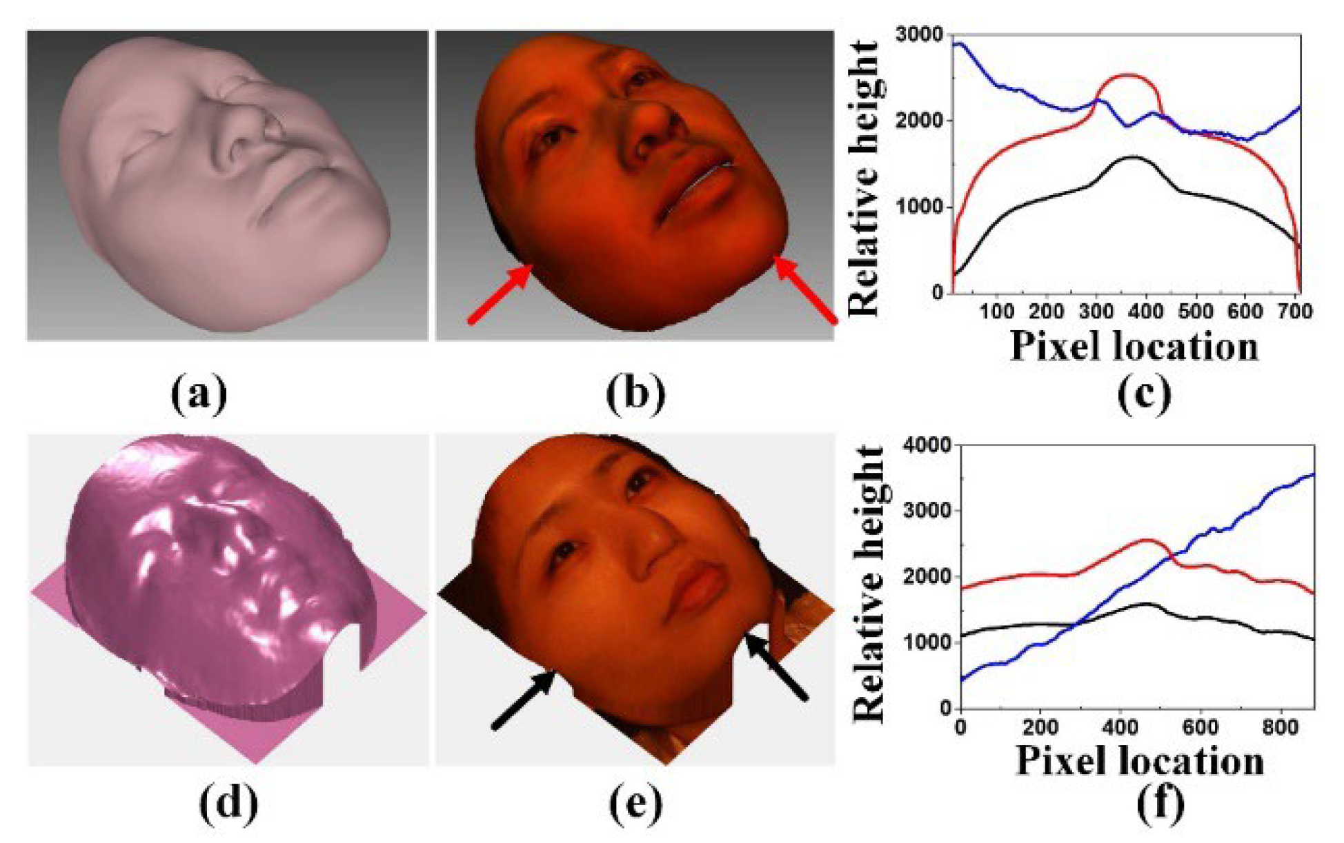
Based on the normal data from the CNN-based 3DMM and polarization, the 3D face reconstruction was implemented according to Equation (12). The targets in Figure 3a–c were the directly reconstructed results from polarization, where 3D information could not be estimated and recovered. For instance, under the influence of the ambiguous azimuth, the relative height information that was higher than the nose area was presented in the facial edge, and the sunken part of the facial area did not correspond with the facial variation trend in reality. In Figure 7a,b, a relative complete 3D face profile consistent with face variations was obtained using the CNN-based 3DMM. Assisted with the data from the CNN-based 3DMM, the final corrected and reconstructed 3D face is shown in Figure 7d,e. The profile information was consistent with the variation trend of the real face. Specifically, the information that was not acquired with the detector at the lower part of the nose was also estimated. Thus, contributing to not only the effective solving of the reconstructed distortion caused due to the uncertainty of the azimuth, but also to the 3D face reconstruction.
Furthermore, relative height value statistics were performed on the face reconstruction results from the CNN-based 3DMM and corrected polarization in the horizontal and vertical directions, as shown in Figure 7c,f. The 3D face profile could be reconstructed using both ways. The variation trends in the horizontal and vertical directions were also consistent with those observed in the real situation. However, we should notice that the faces in the dataset of the CNN were mainly occidental, significantly different from the oriental, with broad foreheads and high noses. Therefore, it could be noticed from the results obtained with the CNN-based 3DMM estimation that remarkable variations could be found in terms of the nose and forehead, which were greatly different from those of the real targets. This issue could also be avoided with the polarization employed for reconstructing a realistic 3D face.
In order to verify the robustness of the proposed method in diversified application scenarios, a 3D face reconstruction was performed under indoor lighting of a male face, outdoor natural illumination of a male face and indoor lighting of a plaster statue, as shown in Figure 8. In all the experiments, no modulated illumination was required. For example, when imaging an outdoor human face, natural illumination is complex, with uncontrolled direction, intensity and polarization. The features visualized in the 3D renderings fit well with their original appearance, and some fine features could be easily identified. Using passive 3D face reconstruction allowed for the developed method to show promise for various potential applications.
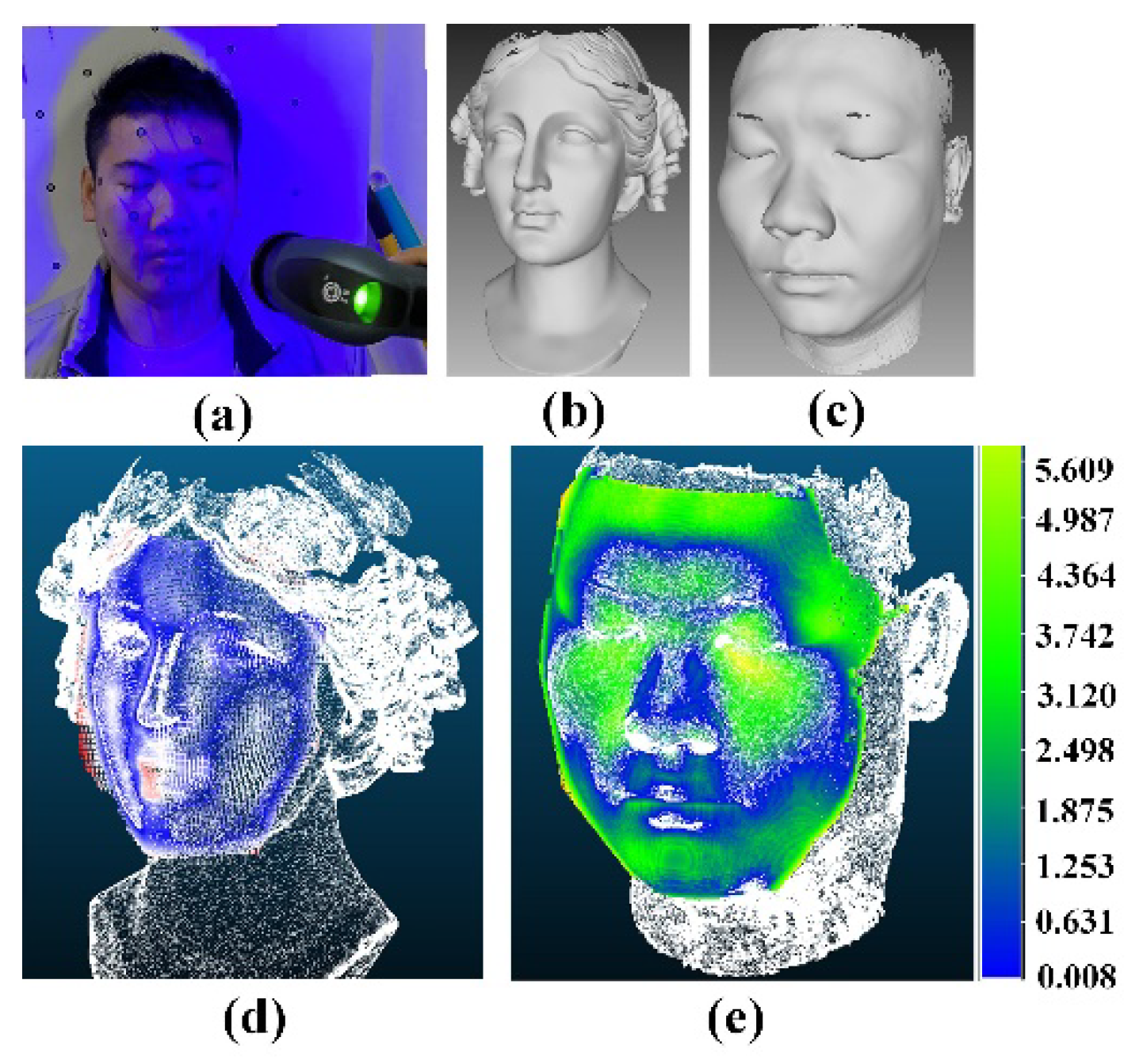
To quantify the reconstruction accuracy of the proposed method, we employed laser scanning technology to conduct the comparison. The 3D data of the human face and plaster statue obtained with an AltairScan Elite scanner, which can achieve an accuracy of 0.01mm, were taken as the ground truth. The scenes and scanned results are shown in Figure 9a–c. The 3D reconstruction results obtained using the proposed method were matched with the scanned results, as shown in Figure 9d,e. The 3D polarization datapoint sets nearly all coincided with the 3D scanned results, showing a high precision in reconstruction. The RMS of Figure 9d,e was approximately 2.707 mm and 2.074 mm, respectively.

4. Conclusions

In this study, we showed that an accurate passive 3D face can be reconstructed from polarization assisted with the CNN-based 3DMM. We acquired a rough depth map from the CNN-based 3DMM method. In addition, it was used as an extra constraint to correct the ambiguous surface normal from polarization and to ensure an accurate 3D face reconstruction. Experiments and results showed that an accurate 3D face could be passively reconstructed with the proposed method. Moreover, the problem of the “average occidental face” generated with the CNN-based 3DMM was also avoided by taking the map as a constraint to the surface normal obtained with polarization. The passive 3D face reconstruction method could potential be used in various applications, including security authentication, face media manipulation, etc.

Author Contributions

Conceptualization, P.H. and X.L.; Data curation, Y.C.; Formal analysis, P.H.; Funding acquisition, Y.L. and X.S.; Investigation, P.H.; Methodology, F.L.; Project administration, X.S.; Software, Y.C.; Validation, K.Y., M.Y. and S.S.; Writing—review and editing, P.H. and X.L. All authors have read and agreed to the published version of the manuscript.

Funding

This research was funded by the National Natural Science Foundation of China (62075175, 62005203); the Opening Funding of Key Laboratory of Space Precision Measurement Technology, the Xi’an Institute of Optics and Precision Mechanics, the Chinese Academy of Sciences (90109220005); and the Opening Funding of Science and Technology on Electro-Optical Information Security Control Laboratory (61421070203).

Informed Consent Statement

Informed consent was obtained from all subjects involved in the study. The human faces displayed in this manuscript are all of the authors of the manuscript, including Fei Liu, Kui Yang, Shaojie Sun and Mingyu Yan. The authors confirmed that informed consent was obtained.

Conflicts of Interest

The authors declare no conflict of interest.

References

  1. Uzair, M.; Mahmood, A.; Shafait, F.; Nansen, C.; Mian, A. Is spectral reflectance of the face a reliable biometric? Opt. Experss 2015, 23, 15160–15173. [Google Scholar] [CrossRef] [PubMed] [Green Version]
  2. Blanz, V.; Vetter, T. A morphable model for the synthesis of 3D faces. In Proceedings of the 26th Annual conference on Computer Graphics and Interactive Techniques, Los Angeles, CA, USA, 8–13 August 1999; pp. 187–194. [Google Scholar]
  3. Thies, J.; Zollhofer, M.; Stamminger, M.; Theobalt, C.; Nießner, M. Face2face: Real-time face capture and reenactment of rgb videos. In Proceedings of the IEEE Conference on computer Vision and Pattern Recognition, Las Vegas, NV, USA, 27–30 June 2016; pp. 2387–2395. [Google Scholar]
  4. Cao, C.; Weng, Y.; Lin, S.; Zhou, K. 3D shape regression for real-time facial animation. ACM Trans. Graph. (TOG) 2013, 32, 1–10. [Google Scholar] [CrossRef] [Green Version]
  5. Hu, L.; Saito, S.; Wei, L.; Nagano, K.; Seo, J.; Fursund, J.; Sadeghi, I.; Sun, C.; Chen, Y.-C.; Li, H. Avatar digitization from a single image for real-time rendering. ACM Trans. Graph. (TOG) 2017, 36, 1–14. [Google Scholar] [CrossRef]
  6. Xie, W.; Kuang, Z.; Wang, M. SCIFI: 3D face reconstruction via smartphone screen lighting. Opt. Express 2021, 29, 43938–43952. [Google Scholar] [CrossRef]
  7. Ma, L.; Lyu, Y.; Pei, X.; Hu, Y.M.; Sun, F.M. Scaled SFS method for Lambertian surface 3D measurement under point source lighting. Opt. Express 2018, 26, 14251–14258. [Google Scholar] [CrossRef] [PubMed]
  8. Koshikawa, K. A polarimetric approach to shape understanding of glossy objects. Adv. Robot. 1979, 2, 190. [Google Scholar]
  9. Wolff, L.B.; Boult, T.E. Constraining object features using a polarization reflectance model. Phys. Based Vis. Princ. Pract. Radiom 1993, 1, 167. [Google Scholar] [CrossRef]
  10. Mahmoud, A.H.; El-Melegy, M.T.; Farag, A.A. Direct method for shape recovery from polarization and shading. In Proceedings of the 2012 19th IEEE International Conference on Image Processing, Orlando, FL, USA, 30 September–3 October 2012; pp. 1769–1772. [Google Scholar]
  11. Atkinson, G.A.; Hancock, E.R. Recovery of surface orientation from diffuse polarization. IEEE Trans. Image Process. 2006, 15, 1653–1664. [Google Scholar] [CrossRef] [PubMed] [Green Version]
  12. Gurton, K.P.; Yuffa, A.J.; Videen, G.W. Enhanced facial recognition for thermal imagery using polarimetric imaging. Opt. Lett. 2014, 39, 3857–3859. [Google Scholar] [CrossRef] [Green Version]
  13. Kadambi, A.; Taamazyan, V.; Shi, B.; Raskar, R. Polarized 3D: Synthesis of polarization and depth cues for enhanced 3D sensing. In SIGGRAPH 2015: Studio; Association for Computing Machinery: New York, NY, USA, 2015. [Google Scholar]
  14. Ba, Y.; Gilbert, A.; Wang, F.; Yang, J.; Chen, R.; Wang, Y.; Yan, L.; Shi, B.; Kadambi, A. Deep shape from polarization. In Proceedings of the European Conference on Computer Vision, Glasgow, UK, 23–28 August 2020; pp. 554–571. [Google Scholar]
  15. Riviere, J.; Gotardo, P.; Bradley, D.; Ghosh, A.; Beeler, T. Single-shot high-quality facial geometry and skin appearance capture. ACM Trans. Graph. 2020, 39, 81:1–81:12. [Google Scholar] [CrossRef]
  16. Gotardo, P.; Riviere, J.; Bradley, D.; Ghosh, A.; Beeler, T. Practical dynamic facial appearance modeling and acquisition. ACM Trans. Graph. 2018, 37, 232. [Google Scholar] [CrossRef]
  17. Miyazaki, D.; Shigetomi, T.; Baba, M.; Furukawa, R.; Hiura, S.; Asada, N. Surface normal estimation of black specular objects from multiview polarization images. Opt. Eng. 2016, 56, 041303. [Google Scholar] [CrossRef] [Green Version]
  18. Kadambi, A.; Taamazyan, V.; Shi, B.; Raskar, R. Depth sensing using geometrically constrained polarization normals. Int. J. Comput. Vis. 2017, 125, 34–51. [Google Scholar] [CrossRef] [Green Version]
  19. Smith, W.A.; Ramamoorthi, R.; Tozza, S. Linear depth estimation from an uncalibrated, monocular polarisation image. In Proceedings of the European Conference on Computer Vision, Amsterdam, The Netherlands, 11–14 October 2016; pp. 109–125. [Google Scholar]
  20. Schechner, Y.Y.; Narasimhan, S.G.; Nayar, S.K. Polarization-based vision through haze. Appl. Opt. 2003, 42, 511–525. [Google Scholar] [CrossRef] [PubMed]
  21. Zhu, H.; Li, D.; Song, L.; Wang, X.; Zhan, K.; Wang, N.; Yun, M. Precise analysis of formation and suppression of intensity transmittance fluctuations of glan-taylor prisms. Laser Optoelectron. Prog. 2013, 50, 052302. [Google Scholar]
  22. Deng, Y.; Yang, J.; Xu, S.; Chen, D.; Jia, Y.; Tong, X. Accurate 3d face reconstruction with weakly-supervised learning: From single image to image set. In Proceedings of the IEEE/CVF Conference on Computer Vision and Pattern Recognition Workshops, Long Beach, CA, USA, 16–17 June 2019. [Google Scholar]
  23. Guo, Y.; Cai, J.; Jiang, B.; Zheng, J. CNN-based real-time dense face reconstruction with inverse-rendered photo-realistic face images. IEEE Trans. Pattern Anal. Mach. Intell. 2018, 41, 1294–1307. [Google Scholar] [CrossRef] [PubMed] [Green Version]
  24. He, K.; Zhang, X.; Ren, S.; Sun, J. Deep residual learning for image recognition. In Proceedings of the IEEE Conference on Computer Vision and Pattern Recognition, Las Vegas, NV, USA, 27–30 June 2016; pp. 770–778. [Google Scholar]
  25. Tewari, A.; Zollhöfer, M.; Garrido, P.; Bernard, F.; Kim, H.; Pérez, P.; Theobalt, C. Self-supervised multi-level face model learning for monocular reconstruction at over 250 hz. In Proceedings of the IEEE Conference on Computer Vision and Pattern Recognition, Salt Lake City, UT, USA, 18–23 June 2018; pp. 2549–2559. [Google Scholar]
  26. Tewari, A.; Zollhofer, M.; Kim, H.; Garrido, P.; Bernard, F.; Perez, P.; Theobalt, C. Mofa: Model-based deep convolutional face autoencoder for unsupervised monocular reconstruction. In Proceedings of the IEEE International Conference on Computer Vision Workshops, Venice, Italy, 22–29 October 2017; pp. 1274–1283. [Google Scholar]
  27. Jones, M.J.; Rehg, J.M. Statistical color models with application to skin detection. Int. J. Comput. Vis. 2002, 46, 81–96. [Google Scholar] [CrossRef]
  28. Jackson, A.S.; Bulat, A.; Argyriou, V.; Tzimiropoulos, G. Large pose 3D face reconstruction from a single image via direct volumetric CNN regression. In Proceedings of the IEEE International Conference on Computer Vision, Venice, Italy, 22–29 October 2017; pp. 1031–1039. [Google Scholar]
  29. Bulat, A.; Tzimiropoulos, G. How far are we from solving the 2D & 3D face alignment problem? (And a dataset of 230,000 3D facial landmarks). In Proceedings of the IEEE International Conference on Computer Vision, Venice, Italy, 22–29 October 2017; pp. 1021–1030. [Google Scholar]
  30. Genova, K.; Cole, F.; Maschinot, A.; Sarna, A.; Vlasic, D.; Freeman, W.T. Unsupervised training for 3d morphable model regression. In Proceedings of the IEEE Conference on Computer Vision and Pattern Recognition, Salt Lake City, UT, USA, 18–23 June 2018; pp. 8377–8386. [Google Scholar]
  31. Frankot, R.T.; Chellappa, R. A method for enforcing integrability in shape from shading algorithms. IEEE Trans. Pattern Anal. Mach. Intell. 1988, 10, 439–451. [Google Scholar] [CrossRef]
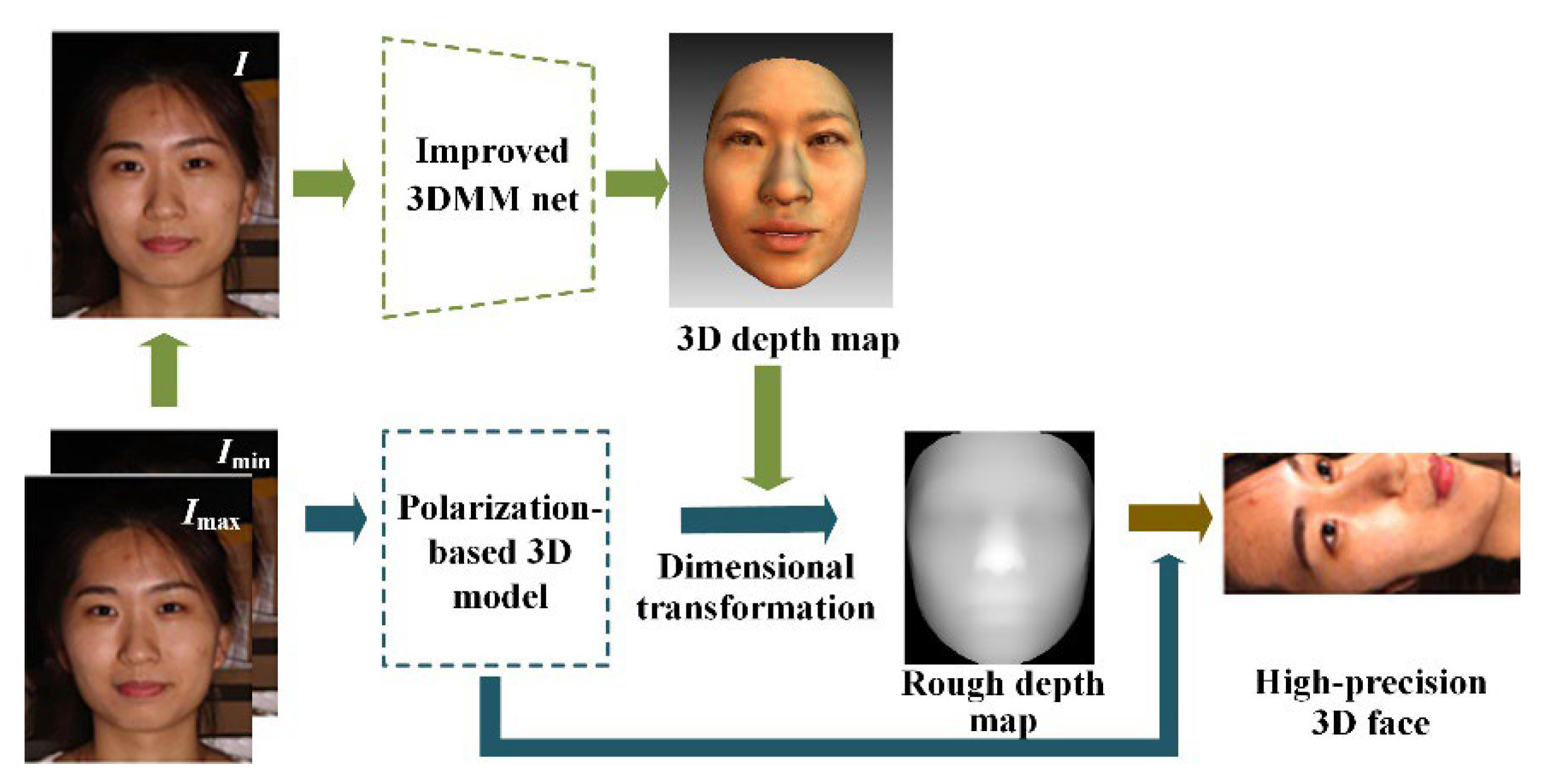
Figure 1. Overall schematic of the 3D face reconstruction method.
Photonics 09 00924 g001
Figure 2. (a) Sinusoidal nature of reflected partially polarized light through a linear polarizer as a function of polarizer orientation; (b) illustration of ambiguous normal.
Photonics 09 00924 g002
Figure 3. Example of deformation caused by ambiguous azimuth, (a) Directly captured human face, (b) Depth map and (c) recovered 3D face deformation caused by ambiguous azimuth.
Photonics 09 00924 g003
Figure 4. Flow chart of network training.
Photonics 09 00924 g004
Figure 5. Reconstructed 3D faces using CNN-based 3DMM; (a) a photo of a Chinese man; (b) a Chinese woman wearing no glasses; (c) a Chinese man wearing near-infrared glasses; (d) a plaster statue; (a1d1) reconstructed face depth profile of (ad); (a2d2) finally, reconstructed 3D face of (ad).
Photonics 09 00924 g005
Figure 6. Surface normal data of the Chinese woman wearing no glasses; (a) four polarization intensity images; (b1,b2) azimuth and zenith derived from polarization; (c1,c2) azimuth and zenith derived from CNN-based 3DMM; (d1,d2) azimuth from polarization and CNN-based 3DMM variation along the red and blue lines; (e1,e2) zenith from polarization and CNN-based 3DMM variation along the red and blue lines.
Photonics 09 00924 g006
Figure 7. Reconstruction of the Chinese woman wearing no glasses; (a) depth profile and (b) 3D face recovered from CNN-based 3DMM; (d) depth profile and (e) 3D face recovered from the proposed method; (c) face profile comparison in the horizontal and (f) vertical directions from Figure 3c and (b,e). Blue, red and black lines indicate profiles from Figure 3c, (b) and (e), respectively.
Photonics 09 00924 g007
Figure 8. Three-dimensional face reconstruction using the developed method. (a) Indoor lighting of a male face, (b) outdoor natural illumination of a male face, (c) indoor lighting of a plaster statue, (a1a3) Three different views of recovered 3D face of (a), (b1b3) Three different views of recovered 3D face of (b), (c1c3) Three different views of recovered 3D face of (c).
Photonics 09 00924 g008
Figure 9. Three-dimensional reconstruction accuracy quantification of the proposed method using laser scanning. (a) Laser scanner and measuring illustration, (b,c) Recovered 3D face by laser scanner; (d,e) point cloud comparison between laser scanner and the developed method.
Photonics 09 00924 g009
Publisher’s Note: MDPI stays neutral with regard to jurisdictional claims in published maps and institutional affiliations.