1. Introduction
Eye-safe lasers in the 1.7 μm band have shown promising applications, such as a pump source for mid-infrared lasers [
1] and a multiphoton fluorescence microscope [
2]. However, lasing emissions in this band are generally hard to achieve due to the lack of optimal rare-earth-doped fibers compared with the 1.1 μm or 1.5 μm band lasing, which can be easily obtained using the ytterbium-doped fiber (YDF) and the erbium-doped fiber (EDF). Although commercial thulium-doped fiber (TDF) has been widely used to excite 1.7 μm band lasing [
3,
4,
5,
6], the limited emission cross-section greatly hinders the efficient optical conversion [
7]. Furthermore, the high cost of TDF also poses a challenge to potential practical applications. Other specially designed active fibers, such as thulium–terbium co-doped [
8] and bismuth-doped [
9] fibers, even show poor performances in lasing. Therefore, another approach, based on stimulated Raman scattering (SRS), shows a more attractive prospect in achieving the 1.7 μm band lasers by employing a high-power pump laser in the 1.5 μm band [
10,
11,
12,
13,
14]. The traditional resonant cavity-based Raman fiber laser approach in this band has been reported for both the solid-core Raman fiber structure [
10,
11,
12] and the hollow-core photonic crystal fiber (PCF) filled with hydrogen gas one [
13,
14]. Although the lasing configurations mentioned above are capable of delivering enough output power and achieving a decent optical efficiency, the relatively low spectral purity blocks its application as a pure light source.
Random fiber laser (RFL) is another popular approach to attain SRS lasing in the 1.7 μm band [
15,
16,
17,
18,
19]. Compared with the abovementioned traditional resonant cavity lasers, RFL employs Rayleigh scattering as the effective optical feedback [
20,
21,
22,
23]. Therefore, the unique open cavity structure leads to a low-noise stable lasing output that is comparable to the traditional amplified spontaneous emission (ASE), which is crucial for the complete power transfer from pumping to the Stokes lasing [
16]. In this way, a Raman Stokes emission with a super-high spectral purity can be obtained. The previously reported 1.7 μm band RFLs could be classified into two categories in terms of the initiated gain medium. The first one is based on the initiated gain in the YDF and the amplification of the cascaded SRS effect in Raman fiber, which is specially designed with a longer zero-dispersion wavelength (i.e., ZDW >1.8 μm) in order to prevent the spectral broadening caused by four-wave mixing (FWM) near the ZDW range [
16,
17,
18,
19]. Additionally, an ASE source is routinely required as the effective pump in this approach to realize a higher spectral purity. Therefore, both the significant complexity and relatively high cost of the structure with integrating the high-power ASE pump source and the specially designed Raman fiber limit the future development in practical applications.
To alleviate or even completely solve these problems, we proposed a 1.69 μm RFL with high spectral purity in a common cavity structure [
24]. The initiated gain utilizes erbium/ytterbium co-doped fiber (EYDF), while the standard single-mode fiber (SMF) can be directly employed as the Raman gain medium, which is free of the spectral broadening effect. It is worth noting, however, that the lasing performance of the 1.7 μm band random lasing is mainly determined by the stability features of the 1.5 μm band pumping. Although the common cavity structure is endowed with excellent compactness and robustness among all the previously realized 1.7 μm band RFLs, the 1565 nm random lasing is vulnerable to external interference from the SMF’s distal end, especially under a high power operating regime. Therefore, the std/mean value shows a relatively large fluctuation in the long-time output regime, while the further power scaling capability is also restricted due to the appearance of spectral instability. Another work, based on a hybrid gain mechanism, is also proposed to lower the lasing threshold and achieve an incredible one hundred percent spectral purity across the entire power scaling range, thanks to the backward-pumped scheme [
25]. However, a gain-modulation-induced random pulsing operation is observed in the short-time regime, which also limits its application as a low-noise pumping source. Therefore, in consideration of achieving highly stable 1.7 μm band lasing for a practical scenario, the 1.5 μm band random pumping should be separated from the 1.7 μm band lasing.
In this paper, we propose a 10-watt-level 1.7 μm RFL with a super-high spectral purity and stable output in a cost-effective and robust structure. To increase the spectral purity and stabilize the 1.7 μm RFL, the pumping laser (i.e., the 1565 nm RFL) in this experiment was separated by the SRS process with the insertion of a high-power optical isolator. Therefore, a ~15 W random lasing at 1565 nm is initially obtained, and then the 1694 nm Raman Stokes emission is excited with a ~10 W maximum output power. An extremely high spectral purity is also achieved with a spectrum contrast of 26.9 dB between the 1694 nm lasing and 1565 nm pumping, which mainly benefits from the highly stable random lasing-based pumping source. Moreover, the obtained high-power 1694 nm random lasing shows excellent stability at both the short-time temporal dynamical regime and the long-time output power regime. Theoretical analysis is also considered in order to provide a full understanding of the proposed structure’s power characteristics and facilitate the potential optimization in need. The combined high performance and low cost in the robust configuration make this approach one of the most attractive candidates for realizing a powerful lasing source in the 1.7 μm band.
2. Experimental Setup
The experimental setup is systematically depicted in
Figure 1, which comprises two major parts: a random fiber lasing pump source (i.e., the 1565 nm) based on a conventional master oscillator power amplification (MOPA) configuration [
26] and a random fiber lasing based on pure Raman amplification. The initial seed light employs a typical backward-pumped half-opened cavity. Here, a 976 nm laser diode (LD, the maximum output power is 27 W with a core/cladding diameter of 105/125 µm and NA of 0.22) is injected into the inner cladding of a 2.4 m length EYDF (MM-EYDF-12/130-HE, Nufern, Granby, CT, USA, the cladding absorption at 915 nm is 3.10 dB/m, the core absorption at 1530 nm is 70 dB/m, the core NA is 0.2 and the first cladding NA is 0.46) through a (2 + 1) × 1 combiner. At the distal end of the EYDF, a 1565 nm high-reflectivity fiber Bragg grating (HR FBG) (3 dB bandwidth of 0.23 nm), serving as a point reflector, is deployed. Moreover, a 2 km length SMF (G.652D) is directly connected at the combiner’s signal port, which provides effective optical feedback by the Rayleigh scattering effect along the SMF.
Then, the seed lasing is injected into the power amplifier stage through an isolator (ISO) to avoid optical reflection. The amplifier stage is composed of two additional 976 nm LDs (the maximum output power is 100 W each with a core/cladding diameter of 105/125 µm and NA of 0.22), another combiner, a piece of extra 4 m length EYDF (MM-EYDF-12/130-HE, Nufern), and a high-power ISO (20 W). In addition, the length of the EYDF is chosen mainly based on the experimental experience. A better lasing performance is anticipated by further optimizing the gain fiber lengths in both the seed and amplifier stages. To strip the residual 976 nm pump and reduce the insertion loss caused by the mode mismatch of different fibers, a fiber device composed of a cladding power stripper (CPS) and mode field adaptor (MFA) is spliced between the high-power ISO and the EYDF. In practice, the CPS and the MFA are packed into a single component, as illustrated in the experimental schematic diagram. Since we aim to achieve a high-power lasing operation in this work, the tremendous thermal loading of the EYDF, induced by the large quantum defect in the power amplifier stage, should be efficiently dissipated to avoid damage to the active gain fiber. Therefore, the coiled EYDF is directly immersed in a water sink.
The final output of the MOPA configuration is then injected into a 3.17 km length SMF through a 1694 nm HR FBG (3 dB bandwidth of 0.31 nm). It is worth mentioning that the length of the SMF is chosen to realize a larger power scaling range, where a comparatively lower random lasing threshold of first-order Raman Stokes is realized with a higher lasing threshold of second-order Raman Stokes. The fiber ends are all angle-cleaved to eliminate the parasitic laser reflections and ensure a half-open cavity structure. The output is monitored by a power meter (919P-250-35, Newport, Irvine, CA, USA), an optical spectrum analyzer (AQ6375B, Yokogawa, Japan), a photodetector (DET10D2, Thorlabs, Newton, NJ, USA), an oscilloscope (MDO4104C, Tektronix, Beaverton, OR, USA), and a radio frequency (RF) spectrum analyzer (N9322C, Santa Rosa, CA, USA).
3. Experimental Results
The performance of a Raman fiber laser is strongly dependent on the lasing characteristics of its pumping source. Although the maximum output power of the pump source directly restricts the available power of the Raman lasing, the relative intensity noise figure plays a more prominent role in achieving a larger power scaling range [
16]. Previous research revealed that a stable pump source, characterized by a lower relative intensity fluctuation in the temporal domain, is critically important in achieving a complete power conversion and a high spectral purity. In contrast, for the pump source with large intensity fluctuations, the average power conversion from the pump to the Raman Stokes would not be so efficient since the instantaneous energy of the pump laser components at some particular moments can possibly be well below the lasing threshold and the spectral purity is restricted [
18]. Therefore, the previously reported 1.7 μm band fiber lasers with high spectral purity mostly employed temporally stable ASE sources as the pump rather than the resonant cavity-based ones. A typical common cavity structure, where the 1565 nm RFL-based pumping and the 1694 nm random lasing share the same random distributed Rayleigh scattering along the passive SMF, is proposed in our previous work to realize a high-power output and high spectral purity simultaneously [
24]. Although the common cavity is known for its compactness and simplicity, the 1565 nm pump is also sensitive to potential parasitic feedback, such as the dust adhering to the fiber distal end and the weak reflection from the fiber components, especially under the high-power operation regime. This would destroy the pure open cavity feature of the 1565 nm pump and lead to a larger relative intensity fluctuation in the temporal domain, which would further lower the spectral purity and the pump power conversion to the 1.7 μm band. Therefore, to realize a highly stable and reliable 1.7 μm band lasing, the 1565 nm pump source should be separated from the 1.7 μm band lasing cavity. That is why a high-power isolator is inserted between the MOPA-based 1565 nm RFL pumping and the half-open cavity-based 1694 nm random lasing structure.
Firstly, the output laser performance of the 1565 nm RFL pumping is investigated. The seed of the MOPA-based random lasing pump is composed of a half-open cavity structure using a backward-pumped scheme. The active amplification in the EYDF provides the initiated gain, while the 1565 nm HR FBG and the randomly distributed Rayleigh scattering provide the optical feedback. The power is greatly boosted when the seed light is injected into the power amplifier stage.
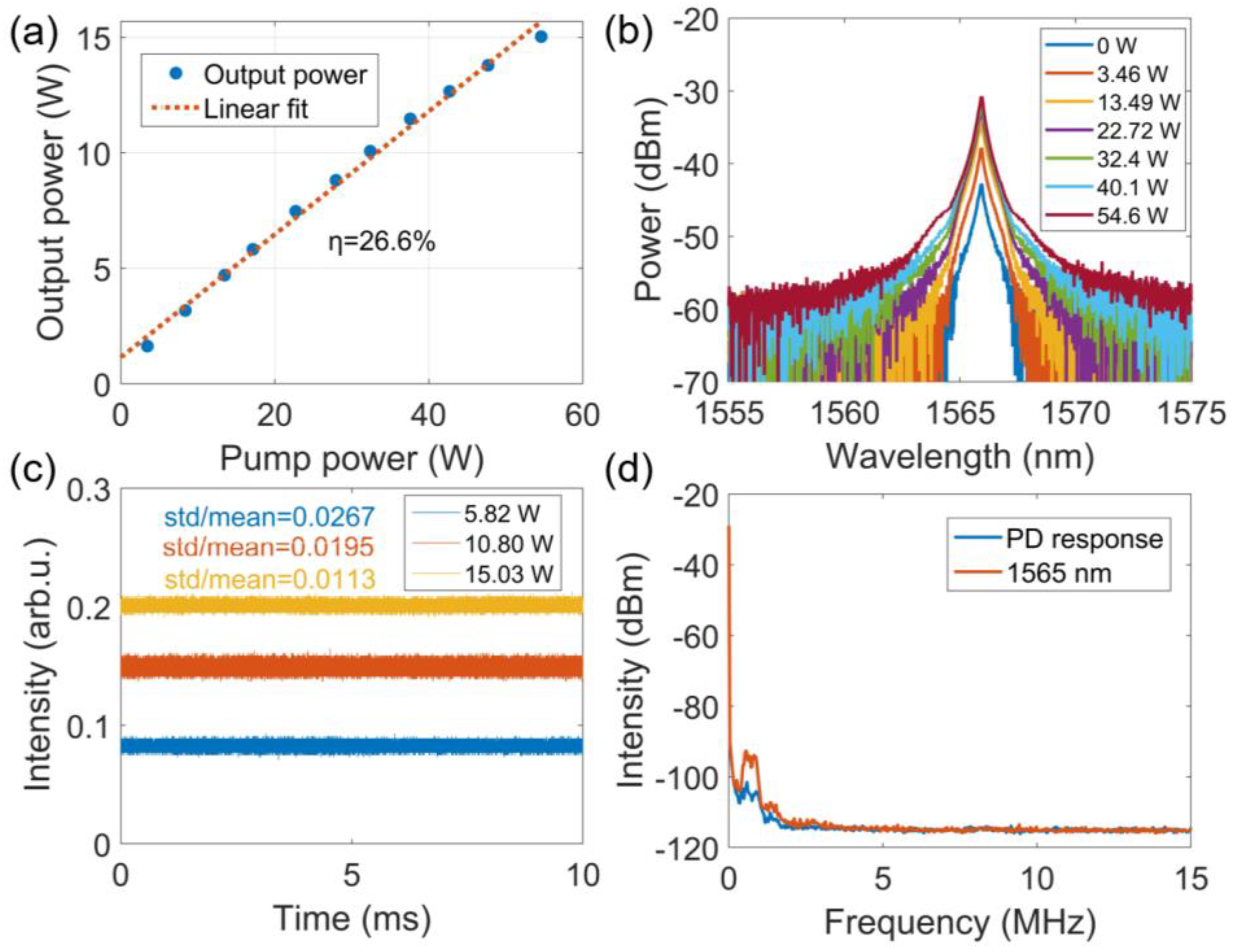
Figure 2a gives the output power of the amplified random lasing as a function of the pump power when the power of the seed is set to 1.5 W. The maximum output power at 1565 nm is 15.03 W under the pump power of 54.6 W, with a slope efficiency of 26.6%. In contrast, with the ~1545 nm random lasing amplified in the similar MOPA-based structure that could emit ~20 W output power, the maximum available power here is limited by the weakened net gain at 1565 nm, which is determined by the intrinsic absorption and emission cross-sections of the employed EYDF.
The optical spectra of the amplified 1565 nm RFL pumping under different pump powers are given in
Figure 2b. The major feature of the amplified RFL based on the MOPA configuration is its spectral-broadening-free output [
27,
28,
29], which means the 3 dB bandwidth of the laser output remains unchanged during the amplification process, while only the spectral pedestal (e.g., the 20 dB bandwidth) undergoes obvious broadening due to the nonlinear effect, such as FWM. It is measured that the 3 dB bandwidth at the output power of 15.03 W (under the pump power of 54.6 W) is 0.31 nm, which verifies the narrow linewidth of the amplified random lasing pump. Therefore, the random fiber lasing keeps the high spectral density and high temporal coherence in the power amplification process.
As has been mentioned above, the temporal intensity characteristics also play a crucial role in achieving an efficient power conversion from the pumping to the Raman Stokes and realizing a high spectral purity output. Therefore, the lasing characteristics in the temporal and radio frequency (RF) domain of the amplified 1565 nm pump are especially evaluated here. The short-time temporal domain traces at different output power are given in
Figure 2c. The temporal intensity dynamics are characterized by the value of standard deviation divided by the mean value (std/mean), which is denoted as the std/mean value. Generally, the temporal intensity exhibits the typical continuous wave operation regime, as shown in
Figure 2c, while the std/mean value is decreased from 0.0267 to 0.0113 as the output power increases from 5.82 W to 15.03 W. The excellent temporal stability is mainly attributed to the half-opened structure, which can strongly suppress the temporal intensity fluctuations compared to a conventional resonant cavity [
30,
31]. The RF spectrum (video bandwidth of 300 Hz) of the amplified 1565 nm pump at a 14.51 W output is shown in
Figure 2d. Only the lower frequency components show a minor uplift over the intrinsic noise floor of the photodetector (PD), and no resonant frequencies are seen throughout the whole frequency bandwidth. All the above results suggest that the amplified 1565 nm random lasing pump fulfills the requirements of a high-performance pump source to realize the complete power conversion.
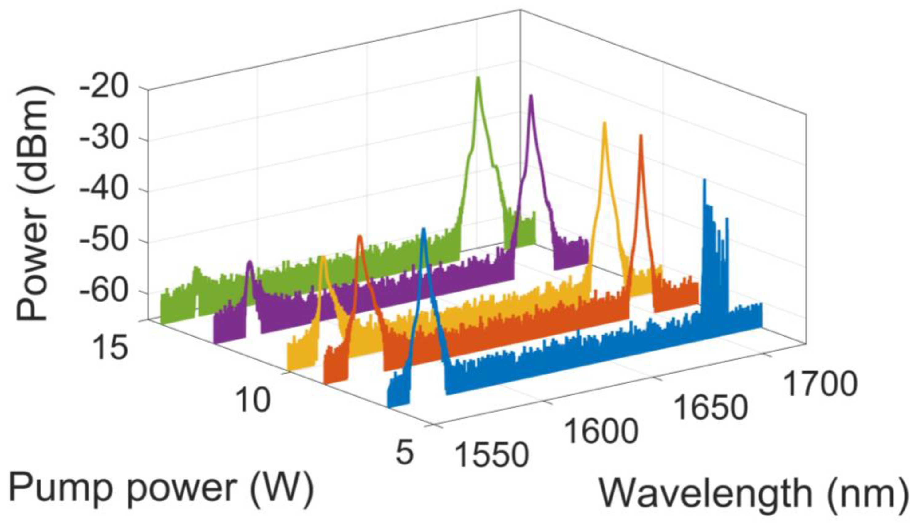
In the Raman Stokes generation stage, when the 1565 nm random pump is added to 6.58 W, stimulated Brillouin scattering (SBS) induced numerous random cascaded frequency spikes to appear within the effective reflection bandwidth of the 1694 nm FBG combined with the randomly distributed Rayleigh scattering, as shown in
Figure 3. With the increase in the pump power, the spectrum at 1694 nm becomes smooth and stable afterward. It is observed that the portion of the 1565 nm residual pump is greatly reduced with the rapid power conversion into the 1694 nm Raman Stokes when further increasing the pump power.
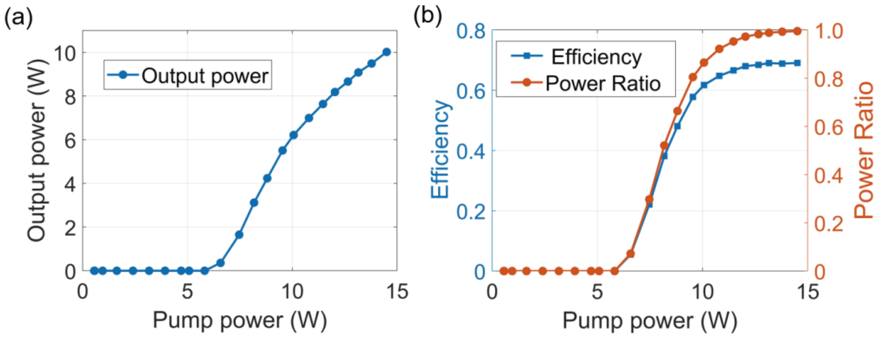
The detailed characteristics of the evolutionary process are given in
Figure 4, i.e., the 1694 nm random lasing output power versus the 1565 nm pumping power in
Figure 4a, and the optical efficiency and power ratio versus the 1565 nm pumping power in
Figure 4b. The random Raman lasing threshold is ~6.58 W, and the output power of the 1694 nm random lasing increases rapidly as the pump power exceeds the lasing threshold. The final output power reaches 10.02 W under the 1565 random lasing pump power of ~14.51 W. It is worth noting, however, that in this regime, the second-order Raman Stokes is still not yet excited, and further power scaling of the 1694 nm lasing is limited by the available power of the 1565 nm random lasing pump.
Figure 4b summarizes the optical efficiency (the power of the 1694 nm divided by the 1565 nm pump power) and the power ratio (the power of the 1694 nm divided by the whole output power) versus the 1565 nm pump power. The optical efficiency reflects the lasing efficiency of the designed structure, while the power ratio evaluates the spectral purity of the output. It is noticed that the optical efficiency gradually increases to ~69% at the highest output power. The power ratio increases rapidly before the 1565 nm random lasing pump power of 10 W and then approaches 0.995 at the maximum output power regime benefiting from the highly stable 1565 nm random lasing pump.
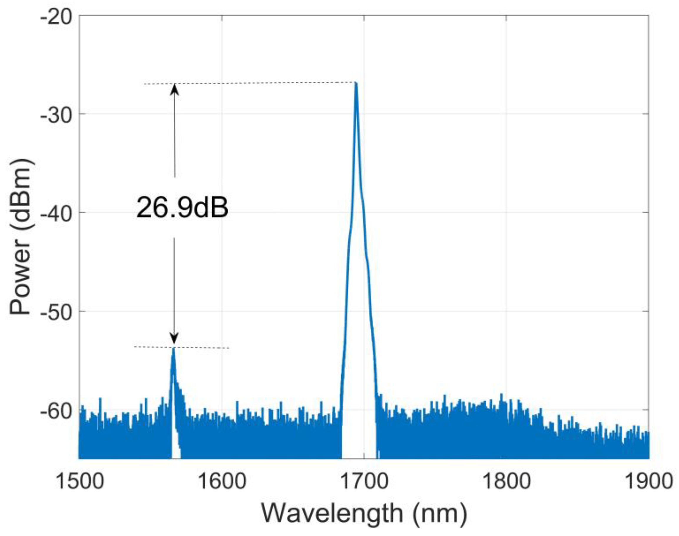
The high spectral purity is illustrated in
Figure 5, which shows the output spectrum from 1.5 μm to 1.9 μm under the 1565 nm pump power of 14.51 W. It is noticed that apart from the random lasing at 1565 and 1694 nm, there are no other laser components across the entire spectrum, especially the second-order Raman Stokes. The spectrum contrast between the 1565 nm RFL pumping and the generated 1694 nm random lasing is 26.9 dB, corresponding to a power ratio of 99.5%. This is also the highest spectral purity for a 1.7 μm band fiber laser obtained so far without using any filtering devices. Due to the half-open cavity and the optimized short SMF length, the second-order random Raman Stokes has a much higher threshold. Therefore, the power scaling range of the 1694 nm random lasing here is mainly restricted by the available pump power of the 1565 nm random lasing.
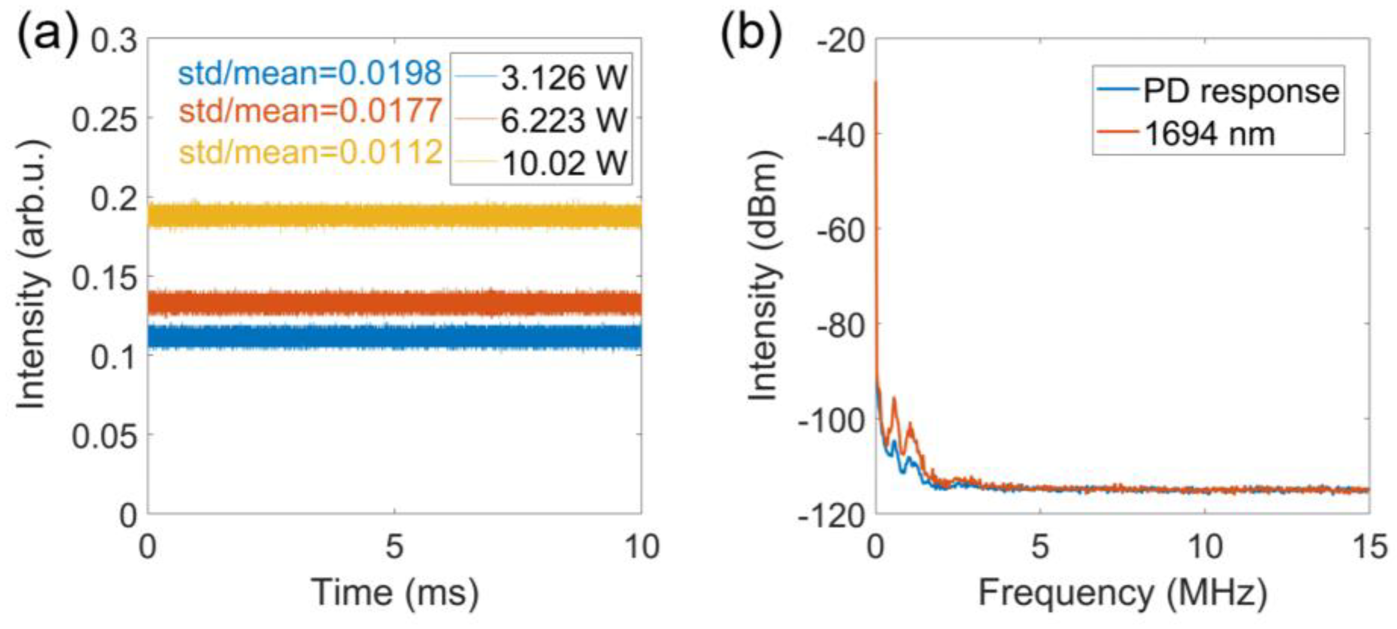
Characteristics in the temporal domain and RF domain for the 1694 nm random lasing are further analyzed, as shown in
Figure 6. The traces in the short-time temporal domain of the 1694 nm random lasing under varied output powers are given in
Figure 6a. With the output power increasing from 3.126 W to 10.02 W, the std/mean value is reduced from 0.0198 to 0.0112, which also benefits from the strongly suppressed temporal intensity fluctuation of the half-open non-resonant cavity. The RF spectrum of the 1694 nm random lasing, in
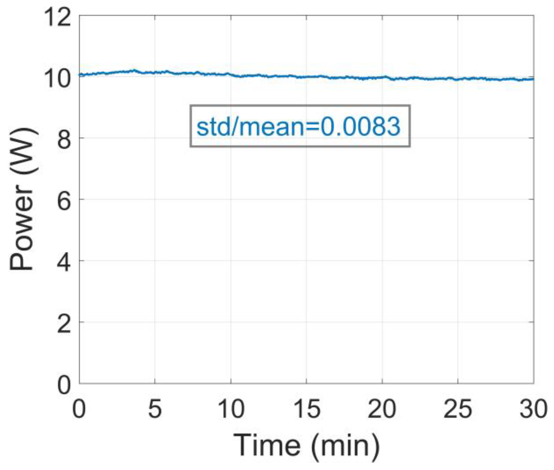
Figure 6b, also shows no resonant frequencies over the entire frequency range, which is similar to that of the 1565 nm RFL pumping. Finally, the long-time (30 min) output power fluctuations of the 1694 nm random lasing are evaluated when the output power is set to ~10 W, as given in
Figure 7. It is worth noting, however, that the 10 W output is almost at the power scaling limitation in this structure. The std/mean value for the whole time window is calculated to be 0.0083, which is extremely low for a high-power lasing output. This also indicates that the random lasing MOPA-based pump source has excellent stable operation capability on a long time scale. In contrast to the previous common cavity-based structures, the separated 1565 nm random pumping scheme contributes greatly to the optimized small long-time power fluctuations. All the above results indicate that the obtained 1694 nm random lasing is an excellent random laser with good temporal stability, which is crucial for practical applications.
4. Theoretical Analysis
To obtain a thorough quantitative analysis of the 1.7 μm RFL pumped by a 1565 nm laser, a theoretical calculation based on the average power balance model has been further considered [
32,
33]:
where subscripts ‘0’, ‘1’ and ‘2’ denote the pump (i.e., the 1565 nm lasing), the first-order Raman lasing (i.e., the 1694 nm lasing) and the second-order Raman lasing (i.e., the 1820 nm lasing), respectively.
represents the average powers of the forward (+) and backward (−) direction with respect to the z-axis direction.
(=0.2, 0.4, 3.2 dB·km
−1) are the fiber attenuation coefficients.
(=0.317, 0.295 W
−1km
−1) are the effective Raman gain parameters at 1694 nm and 1820 nm, induced by the pump at 1565 nm and 1694 nm, respectively.
(=4.5 × 10
−5, 3.3 × 10
−5, 2.5 × 10
−5 km
−1) are the Rayleigh backscattering coefficients.
are the wave frequencies defined by
, where
is the vacuum light speed,
is the wavelength.
represent the populations of phonon, where
is the Plank’s constant,
(=0.05, 0.17 THz) are the lasing bandwidths,
is the Boltzmann’s constant and
(=298 K) is the absolute temperature of the laser.
The above equations then describe the major physical effects, including fiber loss, two orders of nonlinear Raman effects and the distributed Rayleigh backscattering that affect the optical power distribution in the random lasing structure. In order to solve the equation set, boundary conditions based on the proposed random lasing structure are added,
where
is the input pump power at 1565 nm and
(=99%) is the reflectivity of the 1694 nm HR FBG. The boundary conditions correspond to the half-open cavity for the 1694 nm random lasing and the complete open cavity for the 1820 nm random lasing. Relaxation iteration is taken to numerically solve the equations constrained by the boundary conditions. The convergence of the calculation is also monitored by the integrated power difference of the pump wave between two consecutive iterations.
First of all, numerical analyses based on the parameters (e.g., the SMF length is 3.17 km) of the proposed experimental structure are considered. The power distributions of the 1565 nm pump lasing and the forward- and backward-propagating 1694 nm lasing are given in
Figure 8a. The input power of the 1565 nm pump is set at 15 W, corresponding to the maximum power of the 1565 nm random lasing obtained from the MOPA configuration. It is shown that the input 1565 nm pump is majorly transferred into the forward propagating 1694 nm random lasing. The forward 1694 nm output reaches 10.9 W at the distal end of the fiber, which is in accordance with the experimental result when considering the measured insertion loss.
In the experimental work, the maximum power of the 1694 nm lasing is strongly restricted by the available pumping power of the 1565 nm RFL. It is speculated that once the pump power can be obtained as high as possible, the power scaling range of the 1694 nm lasing would be mainly determined by the emergence of the second-order Raman lasing at 1820 nm. Therefore, the capability of the power scaling range of the proposed structure (the length of SMF is 3.17 km) is analyzed, as shown in
Figure 8b. The calculated lasing threshold is 6.44 W, which also coincides with the experimental result. The maximum power of the 1694 nm can reach 16.62 W when the pump power is 23.66 W.
To further achieve a larger power scaling range or a lower lasing threshold, the length of the SMF should be shortened or lengthened accordingly. Here, fiber lengths ranging from 1 km to 5 km, stepped by 0.5 km, are considered in order to predict the lasing power characteristics in terms of the maximum output power, the corresponding pump power and the lasing threshold, which facilitates the potential structural optimization. The lasing threshold, the maximum power of 1694 nm random lasing, and the corresponding pump power of 1565 nm versus the fiber length are plotted in
Figure 8c. For the 1 km length case, the lasing threshold is 21.08 W, while the maximum output power can reach as high as 58.97 W but under a much higher pump power of 69.51 W. For the 5 km length case, the random lasing threshold is as low as 4.12 W, while the maximum output power is 9.97 W when the pump power is 16.58 W. Going back to our experimental section, the criteria for choosing the proper fiber length is based on the trade-off between a relatively lower lasing threshold and a larger power scaling range, determined by the lasing threshold for the second-order Raman Stokes. Therefore, both the power distribution and the power scaling range indicate that the ~3 km fiber length selection is preferable for achieving higher output and a relatively lower lasing threshold.

