Article

Preliminary Characterization of Robust Detection Method of Solar Cell Array for Optical Wireless Power Transmission with Differential Absorption Image Sensing

Laboratory for Future Interdisciplinary Research of Science and Technology (FIRST), Institute of Innovative Research (IIR), Tokyo Institute of Technology, R2-39, 4259 Nagatsuta, Midori-ku, Yokohama 226-8503, Japan
*
Author to whom correspondence should be addressed.
Photonics 2022, 9(11), 861; https://doi.org/10.3390/photonics9110861
Submission received: 24 September 2022 / Revised: 31 October 2022 / Accepted: 3 November 2022 / Published: 15 November 2022

Abstract

:
In an optical wireless power transmission (OWPT) system, position and size of the photovoltaic device (PV) should be accurately determined from the light source position. Even though the detection of PV for OWPT has been studied and reported in some literature, the methods reported thus far are not so robust against varying background illumination. This study aims to solve such problems utilizing an image sensor which generates a differential absorption image from two wavelength images. Unnecessary background illumination presented in the two images is subtracted in the differential image. The differential image of the Si substrate target, which simulates PV, was detected by this sensor from a 104.5 cm distance. Signal illumination intensity was less than 1 μW/cm2 on the target, and detection accuracy was 3.1% for the diameter of the substrate and about 6.3% for the area. The system level requirement is derived, and they were verified by these results. The detection range of this sensor is shown to be expandable at the cost of, for example, increasing the receiver diameter of the image sensor or controlling the transmitter beam’s divergence. With the simple experiment apparatus, preliminary results of performance assessment were obtained and issues for performance improvement and potential of this image sensor were recognized.

1. Introduction

Wireless power transmission includes a variety of systems from a few hundred milliwatts’ transmission power and a few meters’ transmission range [1,2] to large systems of more than a hundred kilowatts’ power and more than a hundred kilometers’ range [3,4]. OWPT transmits a light beam to a photovoltaic device (hereafter, PV) from a light source. Since the ratio of generated electric power in PV to the transmitted beam power is an important parameter of system performance, it is necessary to align the light beam to PV accurately to increase this efficiency. In addition to this, it is also necessary for the transmitted beam to uniformly cover the whole area of the PV. The general tendency is that the further the target is, the stronger these difficulties are [5]. To accommodate these conditions, the light source needs to accurately detect the position and size of PV before and while it transmits the beam to PV. In former OWPT research, recognition of PV was studied by detection of its figure or outline by image processing [6,7,8,9,10,11,12] or using a retroreflector mounted on targets [13]. Trials have been reported to increase recognition power by painting an outline of PV in a specific color, putting a specific shaped marker and installing visible or infrared LEDs blinking with a particular pattern. Utilization of machine learning technology in conjunction with these methods is studied, as well. These methods are reported as successful in certain conditions. However, especially in the case that outdoor background illumination varies by weather or during day and night, recognition is reported to become unstable. This is due to reduction in illumination intensity in some cases or increase in unnecessary light intensity in other cases. Even though it is an important technical challenge in OWPT to recognize PV stably and accurately under varying illuminating conditions, current approaches are not mature enough. Moreover, there are not enough studies so far to numerically estimate conditions, especially accuracy and range for stable detection.
This study proposes a method to solve these problems by utilizing a differential absorption image sensor. The objective of this study is to validate the feasibility of a differential absorption image sensor and to recognize its potential. PV has, in principle, selective absorption characteristics for wavelength. By utilizing this specific feature of PV, more robust detection of PV would be achievable than other methods trying to recognize much more general features, such as shapes or colors. In the method proposed in this study, images are captured in both wavelengths which are strongly absorbed by PV (hereafter, λ ON ) and in the wavelength which is not absorbed by PV (hereafter, λ OFF ). A differential image is generated from two images, and any unnecessary background illumination presented in these images is subtracted in the resultant differential image. Then, the PV image is extracted from it.
In OWPT, it is necessary for image sensors to accommodate necessary system-level accuracy requirements for the recognition of center coordinates and size (area) of target PV. Such requirements are derived. Even though these system-level requirements and performance assessment results depend on experiments and the experimental system, the methodology in this study is general, and it is applicable for deriving other criteria and assessing performances for other systems based on different conditions.
In this paper, the principle of a differential absorption image sensor is introduced in Section 2, and experiments for the detection of an Si substrate, which simulates PV, are reported in Section 3. In Section 4, the system level requirement is studied for the detection of PV. Then, ‘detectability criteria’ is defined as a set of accuracy requirements which shall be simultaneously satisfied by the differential image sensor and ‘detectable range’ as the maximum distance that accommodates the detectability criteria. In Section 5, outcomes of this study are summarized.

2. Principle of Differential Absorption Image Sensor

The differential technique is widely used for contrast enhancement in both signal and image processing. When the target shows different absorption properties for two wavelengths, such a differential technique applied to the absorption image is useful to enhance detection performance [14,15,16]. Regarding OWPT, many PVs are semiconductors, such as Si or GaAs, and their light absorption properties change rapidly with wavelength. Such change is observed in the narrow wavelength range from one side to the other side of the band gap wavelength. On the other hand, comparing with PV, the wavelength’s dependence of absorption and reflection of the environments surrounding PV is expected to be sufficiently flat in such a narrow wavelength range. Thus, differential absorption has a potential advantage for active PV detection in OWPT. Validation of such potential is the objective of this study.
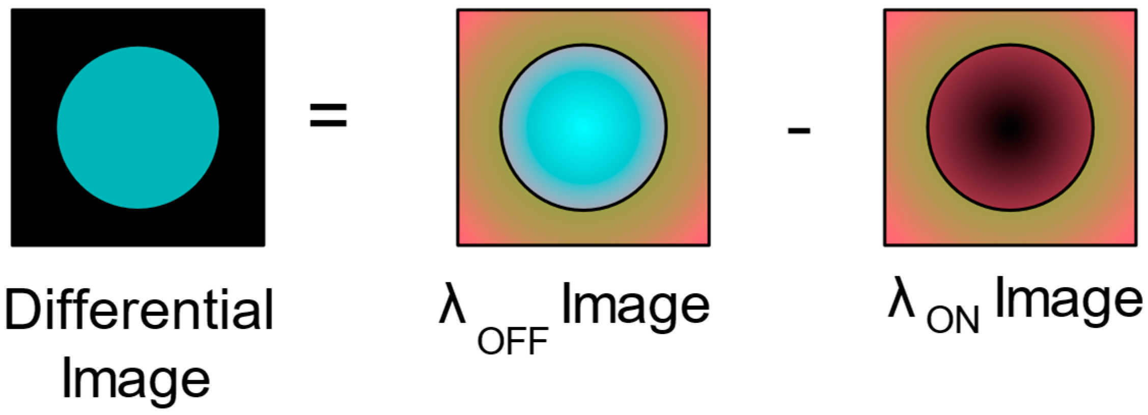
Figure 1 and Figure 2 show the principle of differential absorption in an image sensor. λ ON is assumed to be shorter and λ OFF is assumed to be longer than bandgap wavelength, respectively. In addition, these are assumed to be close enough regarding their reflection that absorption properties for external environments are quite similar. Assume the front surface of PV is processed with low reflectivity for both λ ON and λ OFF and its rear surface is diffuse. This feature would be preferable for this proposed method to stabilize λ OFF reflection from the rear surface. PV is assumed to be thick enough for λ ON to be completely absorbed inside PV. On the other hand, λ OFF is not absorbed and diffusely reflected by the rear surface of PV. A differential image is generated from two images of λ ON , λ OFF , and it is binarized. A PV image is extracted from the binarized differential image, while variating background illumination of the environment is subtracted as a common background. Thus, only PV is detected robustly.
In detail, Figure 1 shows reflections from the front and rear surfaces of PV when λ ON and λ OFF are illuminated. For both λ ON and λ OFF , (a) shows illumination and reflection of the background and (d) shows the reflection from the front surface of PV. Even though PV is processed to be less reflective for both wavelengths, there would remain some reflection light from the front surface. (b) is the λ ON light penetrating into PV, which, in an ideal case, is totally absorbed. (c) shows the λ OFF light penetrating into PV and reflected by the rear surface. Since λ OFF is not absorbed in PV, there are reflection lights from the rear surface. In the Figure 1 system, both λ ON and λ OFF images are captured by the camera and generate a differential image from the two images. The concept of generating a differential image is shown in Figure 2.
In Figure 2, the center circle in both λ ON and λ OFF images represents a PV image, and the area between the circle and the surrounding rectangle is the background image. Since λ ON and λ OFF are close enough, the background images are almost the same for the two images on the right-hand side. The PV image is a superposition of the front surface reflection image and the background reflection image. The front surface reflection is assumed to be quite low, and their images are almost the same for both λ ON and λ OFF , as in the images of the background. On the other hand, reflections from the rear surfaces of PV are zero or quite low for λ ON (‘black’ in λ ON image) and sufficiently high for λ OFF (‘blue’ in λ OFF image). The differential image generated from the λ ON and λ OFF images is the left-hand side image in Figure 2, and it shows that the PV image is captured without any disturbance from the background nor from the front surface reflection.

3. Detection Experiments of Simulated PV

3.1. Design of Experiments

To validate robust and accurate detection of PV by a differential absorption image, preliminary experiments were conducted. Figure 3 shows the experiment apparatus. An Si substrate (two-inch diameter) was utilized to simulate PV. Its front surface was flat and polished, and its rear surface was flat and diffuse. For experiments, two kinds of samples were prepared. In one sample, the Si substrate was attached to a 10 cm × 10 cm frost glass plate (hereafter, Si target). The other sample is a frost glass of the same size without the Si substrate (hereafter, frost glass target). The frost glass simulates a reflection from the rear surface of PV and the background. In this preliminary research, instead of switching two wavelengths of λ ON and λ OFF , the single wavelength λ = 532   nm was utilized, which is absorbed by Si. This made the experiment easier to execute than handling two invisible wavelengths of infrared, and a general visible light camera can be used instead of a camera for a special wavelength for image acquisition. Two images were captured by switching the above two samples. For λ = 532   nm , the Si target behaves like PV illuminated by λ ON , and the frost glass target behaves like PV illuminated by λ OFF . This configuration is equivalent to a two wavelength one. A differential image was generated from the two images of these samples.
Furthermore, for the image capturing camera, a small, off-the-shelf product was used without any zooming capability. With the simple experiment apparatus, the essence of preliminary concept validation was focused on. With such a simple but equivalent experiment configuration, preliminary results of performance assessment were obtained, performance improvement was predicted to be verified in experiments with more a complex apparatus and issues were identified. These are described in later sections.
In actual operation of OWPT, illumination by two beams of λ ON ,     λ OFF is utilized for target detection. Since the two wavelengths are close enough to each other, the optics of main power transmission beam of OWPT are commonly usable for optics of both λ ON ,     λ OFF beams. Especially for the λ ON beam, the main power transmission beam of OWPT itself is commonly usable with power adjustment. In some application scenarios, these two-wavelength lights will be prepared as lighting for the area. Regarding the image-capturing camera, since performance of this image sensor is beyond the resolution limit of it, a zoom lens will be necessary for the long range system.
As shown in Figure 3, the light source was λ = 532   nm and CW and power were 5 mW, with an almost top-hat beam pattern. The distance between the RGB camera and Si/frost glass target was 104.5 cm. The diameter of the beam was 7.4 cm when it irradiated the target directly. Since the beam was arranged to irradiate the target uniformly and to be large enough, compared with the FOV of the camera, the fly eye lens was always set in front of the light source during data acquisition. To control uniform irradiation power onto the target in detail, some white scattering ‘filter papers’ were placed in front of the light source. To change the intensity on the Si/frost glass target, the amount of filter paper was varied. It should be noted that intensity reduction on the Si/frost glass target is equivalent to scattered light around the surrounding environment. Such background intensity is subtracted in data processing. Regarding the image capturing camera, 640 × 480 pixel (px) RGB images were acquired by Intel’s Realsense D435TM [17]. Even though this camera supports to output depth information, these experiments did not employ it.

3.2. Acquired Raw Data in the Experiment

The γ parameter, which indicates the intensity response characteristics of an image, of Realsense was set by its internal parameter GAMMA = 450 by PC. For parameter setting and control software for the camera, RealsenseTM SDK [18], Open CV [19] and Python [20] were utilized. Correspondence between γ and GAMMA is studied in a later section. A every time of data acquisition, the exposure time of the camera (39, 78, 156, 412, 625, 1250, 2500, 5000, 10,000 μ sec ) was set and reconfirmed by PC. Other internal parameters of RealsenseTM were not changed from their default values. To control intensity on the Si/frost glass target, the amount of filter paper was varied between 0, 1, 5, 10, 15 and 20 (hereafter, P0, P1, P5, P10, P15, P20). Consecutively, 100 images were taken for both the Si target and frost glass target, with every combination of the parameter set of exposure time (39, 78, 156, 412, 625, 1250, 2500, 5000, 10,000 μ sec ) and the number of filter papers (P0, P1, P5, P10, P15, P20).
To assess intensity reduction by a fly eye lens for calibration, the frost glass intensity of the diffuse reflection was also measured using the frost glass target with and without a fly eye lens. These data were taken as varying the number of filter papers.
An example of raw data acquired in the experiments is shown in Figure 4. Figure 4a is frost glass target data acquired with λ = 532   nm light source illumination. Figure 4b is a sample with the Si target acquired under the same conditions. A black circular object centered in Figure 4b is the Si substrate, and the white diffusing rectangular image surrounding the Si substrate is the frost glass. The frost glass is seen in Figure 4a image, as well.

3.3. Data Processing and Software Tools

Acquired image data were processed after trimming. The following several trimming sizes were investigated in this study: 48 × 49, 72 × 71, 95 × 95, 143 × 143, 237 × 237, 331 × 331, 384 × 448, 384 × 480 and 640 × 480 px. In this study, the relative position between the camera and sample were fixed, and the image was trimmed for each image size so that the position (center coordinate) of Si in the trimmed image varies with trimming size. It does not vary among the same trimming size images. On the other hand, the area of the Si image does not vary with trimming size nor among the same trimming size images. The default size used for image processing in this study was 48 × 49 px, except in investigation regarding trimming size’s effect on ‘detectability’, described in a later section. For trimming, image processing and data analysis software, MathematicaTM [21] was used.
After trimming, a differential image was generated and binarized. Then, the Si image was extracted. The position of the Si image was determined in local coordinates of each trimmed image. Figure 5a is a binarized image including Si, and Figure 5b is a boundary rectangle of the extracted Si image superimposed on the original differential image before binarization. The data analysis process is described in a later section.

3.4. Calibration of Experiment System

First, as calibration of the experiment system, Realsense’s internal γ value after setting GAMMA = 450 was estimated. Since the estimated γ value was close to 1 (one), γ parameter correction is not applied in the following data analysis.
Next, the intensity reduction factor on Si/frost glass targets was estimated in the following manner: The fly eye lens and the filter papers set in front of the camera reduce the intensity of λ = 532   nm on the Si/frost glass targets. Intensity reduction on the samples is represented by intensity reduction factor T , defined as below:
T = E w / FE ,   P / E w / o   FE ,   P = T FE × T p ( n )
E w / FE ,   P represents intensity on the Si/frost glass targets through both the fly eye lens and the filter papers. Since it should be background free, if there is any non-negligible intensity from background illumination, such background should be subtracted. E w / o   FE ,   P represents intensity with neither the fly eye lens nor the filter papers. This should also be background free. Since the fly eye lens and the filter papers provides independent contribution to intensity reduction, T is factorized as T FE × T p ( n ) . T FE represents the contribution from the fly eye, and T p ( n ) represents the contribution from the filter papers, which depends on the number of papers ‘n’. Details of estimations are summarized in Appendix A. Estimation of T p ( n ) shows T p ( n ) = ( 0.13 ) n and T FE = 0.06 ± 0.03 . These parameters are used in a later section. From estimation of T p ( n ) and T FE , intensity on the Si/frost glass targets for the number of filter papers is calculated in Figure 6. Note that in the calculation, the following numbers are used to calculate absolute power on the target. Light source power is 5 mW, and the beam diameter on the Si/frost glass is 7.4 cm when any filters and lens were not introduced.

3.5. Data Processing of Acquired Image

The 640 × 480 px size images, which are taken from Si/ frost glass targets with λ = 532   nm light source illumination, are trimmed down to images of 9 trimming sizes. To extract an Si image from the trimmed images, data processing continues to generate differential images and binarize them. Regarding the binarization scheme, the Otsu algorithm [22], implemented in Mathematica [23], is exploited, in which the binarization threshold is determined globally as providing the minimum of each variance of two classes dividing the whole image histogram. Generation of differential images and their binarizations is conducted in the following manner:
  • First, 100 raw 640 × 480 px image data points of the frost glass target ( λ OFF image: Img OFF ( Exp ,   P ,   i ) raw ) and 100 same-size images of the Si target ( λ ON image: Img ON ( Exp ,   P ,   i ) raw ) are taken for each combination of parameter set (Exp = 39, 78, …, 10,000 μsec and P = 0, 1, …, 20, i = 1, 2, …, 100).
  • These images are trimmed down to each image size (48 × 49, 72 × 71, 95 × 95, 143 × 143, 237 × 237, 331 × 331, 384 × 448, 384 × 480, 640 × 480 px) and grayscaled.
  • For each λ ON , λ OFF image data point, P20 data are regarded as background data, and their grayscaled images are subtracted from Img ON ( Exp ,   P ,   i ) raw , gray and Img OFF ( Exp ,   P ,   i ) raw , gray . Then, background-free 100 λ ON and 100 λ OFF grayscale images are generated, respectively.
    Img OFF ( Exp , P ,   i ) = Img OFF ( Exp ,   P ,   i ) raw , gray Img OFF ( Exp ,   20 ,   i ) raw , gray
    Img ON ( Exp ,   P ,   i ) = Img ON ( Exp ,   P ,   i ) raw , gray Img ON ( Exp ,   20 ,   i ) raw , gray
  • One hundred differential images are generated for each combination of the parameter set of exposure time and the number of filter papers by subtracting the grayscale level of the λ ON image from the λ OFF image.
    Img Diff ( Exp , P ,   i ) = Img OFF ( Exp , P ,   i ) Img ON ( Exp ,   P ,   i )
  • Differential images are accumulated n times n=1, 2, …, 100.
    Img Acc ( Exp , P ,   n ) = i = 1 n Img Diff ( Exp ,   P ,   i )
  • Generated   differential   images   are   binarized   by   Otsu   algorithm .
    Img Bin ( Exp ,   P ,   n ) = Binarize [ Img Acc ( Exp , P ,   n ) ]
As an example of 5 and 6 above, differential images and binarized images of trimming size 48 × 49 px and exposure time 10,000   μ sec are attached in Appendix B.
Differential images and binarized images as in Figure A7 vary with the number of filter papers and the number of accumulations. They also vary with exposure time (39, 78, 156, 412, 625, 1250, 2500, 5000, 10,000 μ sec ) and trimming size (48 × 49, 72 × 71, 95 × 95, 143 × 143, 237 × 237, 331 × 331, 384 × 448, 384 × 480, 640 × 480 px). Both differential images and binarized images are generated for all combinations of these parameter sets, and Si images are extracted from each binarized image. By the following procedures, the center coordinates, the area and the SNR are calculated from the extracted Si images:
7.
From the binarized image by Equation (6), the connected component with maximum area is extracted, and this is regarded as the Si image.
Si   Image connected   component   with   max   area   in   Img Bin ( Exp ,   P ,   n )
8.
The center coordinates are calculated as the center of the boundary rectangle of the extracted Si image.
Center   cordinates ( Exp ,   P ,   n ) center   coordinates   of   boundary   rectangle
9.
The area is calculated as the area of the extracted Si image.
Area ( Exp ,   P ,   n ) area   of   Si   image
10.
Regarding signal intensity, the Si portion is extracted from the λ OFF image by image multiplication of the λ OFF image and the binarized Si image. Then, signal intensity is calculated as the mean intensity of the extracted Si portion of the λ OFF image. Noise intensity is calculated as the P20 mean intensity of the frost glass target with light source OFF. SNR is calculated as the ratio of signal intensity to the noise intensity. To avoid instability, such as that which occurred in estimation of T FE , described in Appendix A.2, the definition of SNR uses raw image data.
SNR ( Exp , P ,   n ) mean   intensity   of   [ Img OFF ( Exp ,   P ,   n ) raw ×   Img Bin ( Exp ,   P ,   n ) ] mean   intensity   of   [ Img OFF ( Exp ,   20 ,   n ) raw ]
To assess performances of the image sensor, determined values, such as the center coordinates and the area of the Si image, were compared with true coordinates and values of the area which were measured from differential images before binarization. For measurement of true value, high SNR images were used, such as P0 and Exp = 10,000 msec. The measured true area is the same for all combinations of parameter sets and the measured true center coordinates are the same for all combinations of parameter sets, unless the trimming size were to change. In the case of a 48 × 49 px trimming size, the true center coordinates of the Si image that directly read out from the differential image are (X: 27.68, Y: 21.67), and the true value of the area is 706.85 px (circle image of 15 px radius).
For a 48 × 49 px trimming size, the determination error of X, Y center coordinates and area is plotted for exposure time. Figures are attached in Appendix C. Similar plots were generated for other trimming sizes and analyzed in a similar manner.

4. Discussion

4.1. Detectability Criteria

Even though all the data in the experiments were taken at 104.5 cm from the Si/frost glass targets, the real target will be at some different distance in actual operation. Regarding center coordinates and area of the target, it should be required that accuracy of determination be within some limits. The maximum distance to the target that accommodates the requirements of error will depend on exposure time, the number of accumulations or the number of averaging and trimming sizes. The performance of this image sensor is defined as the maximum distance which accommodates determination of the center coordinates and the area of PV, which is, in this experiment, the Si substrate, within required error limits. To assess this performance, system-level requirements for errors are necessary. These requirements are derived from a discussion based on the power generation ratio. The power generation ratio has been discussed in previous studies [5,24]. Then, an equation which determines the maximum distance is derived. In this study, that differential absorption image sensor accommodates the requirement is referred to as ‘target is detectable’, and the maximum distance which accommodates the requirements is ‘detectable range’.

4.1.1. Cooperative OWPT Utilizing Fly Eye Module

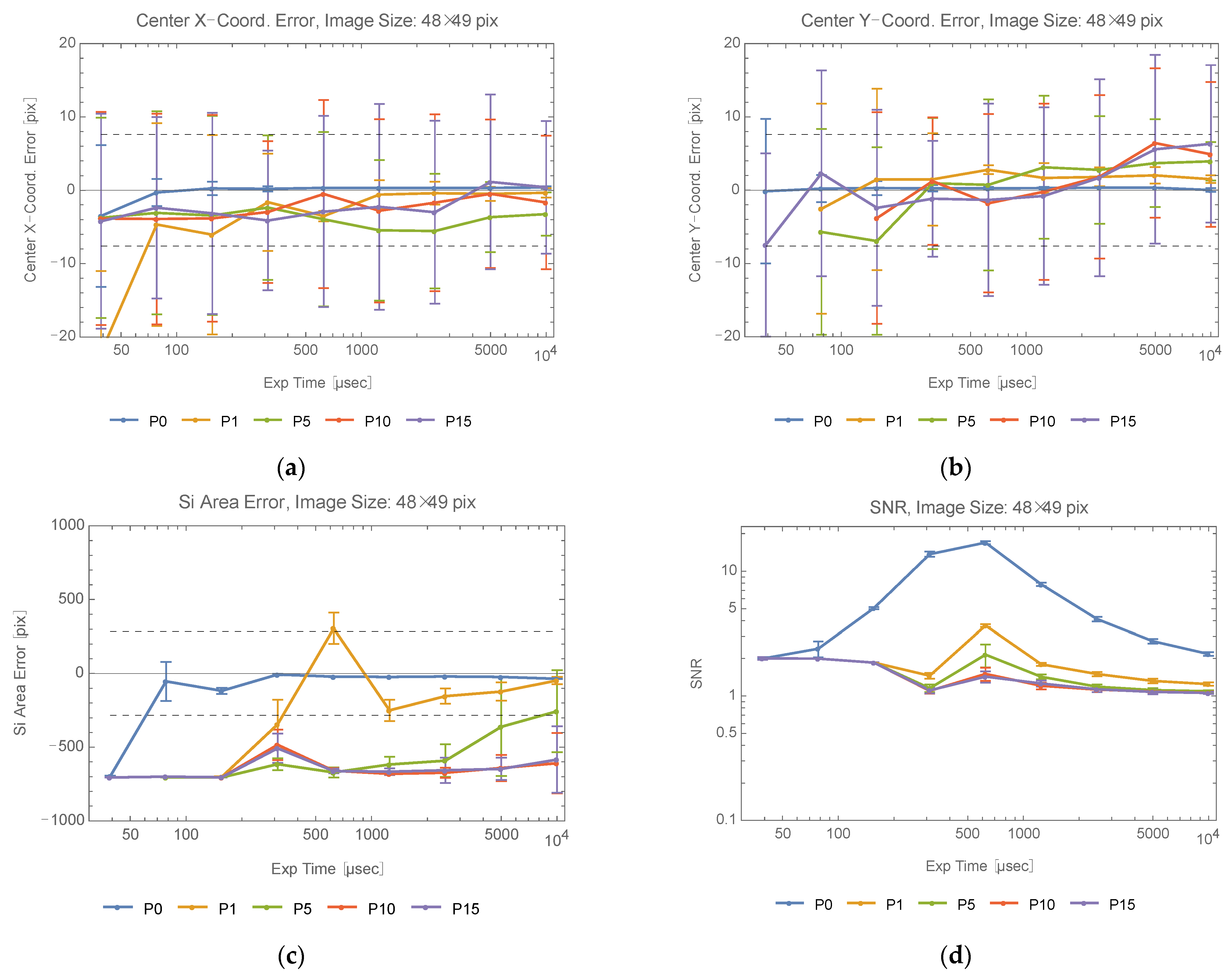
There are two kinds of OWPT system. One is cooperative OWPT, the other is non-cooperative [5]. In cooperative OWPT, utilization of a fly eye module relaxes the system-level requirement with regard to beam alignment and shaping [25,26]. When fly eye lenses and a condenser lens are integrated with PV, they form a fly eye module. In case a fly eye module is utilized, the power generation ratio is basically determined only by the overlapping ratio of the incident beam to the area of the fly eye module. When the incident beam size is smaller than the fly eye module size and no portion of the incident beam is outside of the fly eye lens, then the power generation ratio becomes 100%. Large errors of the center coordinates decrease the overlapping ratio, then, also, the power generation ratio. In the following discussion, both the fly eye module and the incident beam are considered to be circles, and their radii are R (=15 px), R/2, respectively. It should be noted that the radius of the incident beam is not 15/2 px in the experiment. Let ( Δ x ,   Δ y ) be errors in x direction and y direction, respectively. The overlapping region ( x , y ) satisfies the following relationship: { ( x , y ) x 2 + y 2 R 2 } { ( x , y ) ( x Δ x ) 2 + ( y Δ y ) 2 R 2 / 4 } . Assume the usable lower limit of the power generation ratio from the system point of view is 80%. Then, ( Δ x , Δ y ) is determined such that the area of this overlapping region is greater than 80% of the area of the beam ( 0.8 × π R 2 / 4 ). Since it is sufficient to consider only the X direction, then, setting Δ y = 0 and by numerical calculation, Δ x is determined to be Δ x 0.718 × 15   px = 10.77   px . A requirement is allocated for each X, Y direction as ± 10.77 / 2 = ± 7.6 px. During operation, beam area information is necessary when the beam size R/2 ( r ) ratio is adjusted to the fly eye module size R. In the assumption adopted in this study, it is not necessary for this ratio (1: 2) to be quite as rigorous and accurate as the beam area (S) determination is. Since Δ S / S = 2 Δ r / r = 4 Δ r / R , and error allocation is set as Δ r / R ± 0.1 , then the requirement for the area determination is Δ S ± 0.4 S = ± 282.74 .
These requirements are already included in Figure A8 and Figure A9 in Appendix C as horizontal dashed lines. If accuracy of only the center coordinates’ determination or of the area determination is required, there could be a possibility of accidental accommodation of each requirement. To avoid such an accidental case, all three requirements, which are the accuracy of X and Y center coordinates’ determination and accuracy of the area determination, are required. Hereafter, that a differential absorption image sensor accommodates all the three requirements is referred to as ‘it accommodates detectability criteria’.

4.1.2. Cooperative/Non-Cooperative OWPT without Fly Eye Module

In case that a fly eye module is not utilized, it is necessary to assess both the first factor of the power generation ratio (overlapping ratio of incident beam area to PV area) and the second factor (nonlinear output characteristics of PV based on power distribution inside it). Misalignment requirements for such systems were discussed in an earlier study [5]. Assume the usable lower limit of the power generation ratio is 80%, then, when target distance is 1 m, requirements are 2.21 mrad (X direction) and 2.51 mrad (Y direction) for non-cooperative OWPT and 6.9 mrad for cooperative OWPT. Since the angle resolution of Realsense D435 is 1.54 mrad/px in the case of a 640 × 480 px image size, these requirements are equivalent to 1.4 px (X), 1.6 px (Y) for non-cooperative OWPT and 4.5 px for cooperative OWPT. To accommodate these requirements, zooming or a much higher-resolution camera are necessary. Comparing these with requirements for the fly eye module, these are quite strong. In the following section, cooperative OWPT with the fly eye module is investigated.

4.2. Assessment of Detectable Range

Detectability criteria, at a 104.5 cm target distance in the case of trimming size 48 × 49 px, are read from Figure A8 and Figure A9. In the case that 100 data points are accumulated, detectability criteria are not accommodated by any number of filter papers for exposure   time   = 39   μ sec . For 78   ~   156   μ sec , they are accommodated by P0. For 312   ~   10 , 000   μ sec , they are accommodated by P0 and P1. In the case that 100 data points are averaged, detectability criteria are not accommodated for exposure   time   = 39   μ sec . For 78   ~   312   μ sec , they are accommodated by P0. For 625   ~   5000   μ sec , they are accommodated by P0 and P1. For 10 , 000   μ sec , they are accommodated by P0, P1 and P5.
When trimming size is varied like exposure time, the number of filter papers (such as P0, P1, ⋯) which accommodates detectability criteria also varies. Plots, as in Figure A8 and Figure A9, were generated for each trimming size, and the relationship with exposure time and number of papers, such as P0, P1, was read from the figures in a similar manner. According to the following discussion, the number of papers is translatable to the detectable range. Thus, the detectable range is determined for exposure time and trimming size. Therefore, the performance of a differential absorption image sensor is determined by these two parameters.
In the following discussions, target size is assumed to proportionally increase with distance to the target, or the target is proportionally zoomed in with respect to the distance. In this way, detectability criteria at 104.5 cm are applicable to any distance, and the detectable range is calculated by the following SNR discussion. When fly eye lens and filter papers are removed, the detectable range increases from the 104.5 cm in the experiment. In Figure A8 and Figure A9, even though SNR approaches 1 (one) due to the saturation effect as exposure time increases, it appears that SNR monotonically increases with exposure time in the region of the lower saturation effect. If there were not such a saturation effect due to hardware constraints, SNR would increase monotonically with exposure time. Therefore, an SNR value determines corresponding exposure time for each number of filter papers. By the determined exposure time, the error of the center coordinates and the area is determined from the error plots for exposure time, as in Figure A8 and Figure A9. Then, comparing these errors with requirements, conditions such as P0, P1 accommodating detectability criteria are determined.
The detectable range with neither fly eye lens nor filter papers is simulated as in the following equation. The equation is for a system with a diameter of camera optics D and target distance R based on D , R in the experiment ad calibration parameter T FE and T p n .
R 4 = R 4 ( D / D ) 2 / ( T FE T p n )
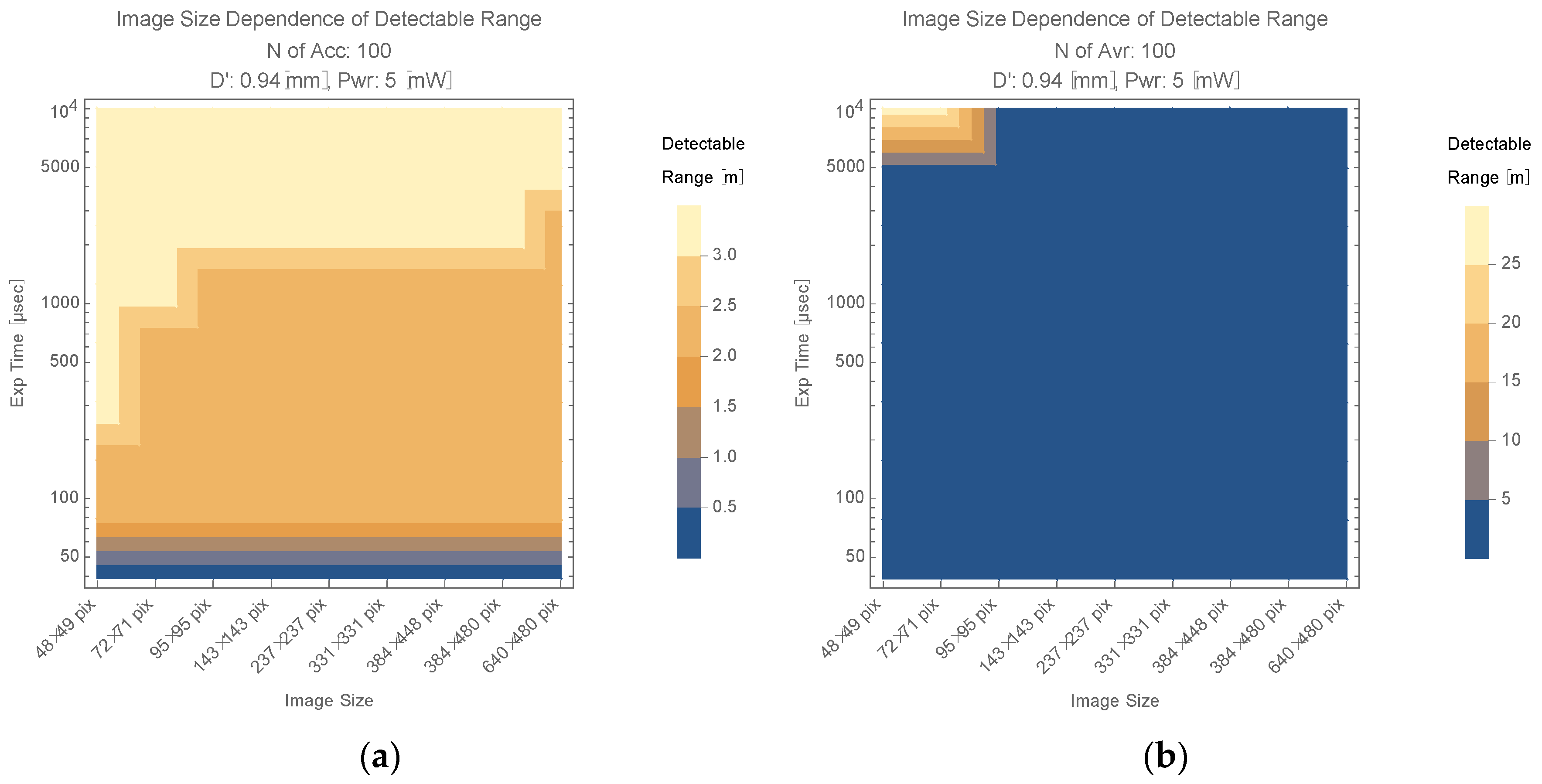
Derivation of the equation is summarized in Appendix D. According to D435′s data sheet [17], F number of its color sensor optics is 2.0, and its focal length is 1.88 mm. Thus, the camera’s diameter D of experiment apparatus is 0.94 mm. R is the distance to the target in the experiments, and it was 104.5 cm. Figure 7 shows simulation results of the detectable range (R’) based on Equation (11) for trimming size and exposure time, in the case that D’ = D. It should be noted that first order interpolation is used in the plot. These plots essentially show an SNR-based performance limit of a system with a 5 mW light source and D435 RGB camera. Plots are shown for two different image processing schemes, accumulation 100 times (Figure 7a) and averaging 100 data points (Figure 7b). The accumulation scheme follows from Equation (5). Averaging does not accumulate data but averages them.
In Figure 7, generally, the detectable range tends to increase as the exposure time increases and image size decreases (the upper left corner). Comparing two image processing schemes, the detectable range is quite enhanced by averaging. The maximum value of the detectable range is about 3.5 m in an accumulation scheme with a 104 μsec exposure time. It reaches around 30 m in an averaging scheme in the case of a 104 μsec exposure time and 48 × 49 image size. This figure indicates that the performance limit of this image sensor is largely boosted when an averaging scheme and trimming down to an appropriate image size are applied. In image processing in this study, binarization is based on the unique threshold determined by the Otsu algorithm in the entire image. As trimming size increases, such a binarizing threshold tends to increase due to effects from objects other than target and noise. On the other hand, in the case that the trimming size is small, the area of the Si image is relatively large and dominant in the trimmed image. In such cases, the binarizing threshold tends to decrease, and the Si image is detectable even for a larger number of filter papers, such as P5 with Exp = 10 , 000   μ sec . When trimming size is small, averaging provides a longer detectable range than accumulation (e.g., upper left corner of Figure 7b). This is because, in addition to the decrease in the binarizing threshold, scattered data tend to converge close to the true value by averaging. This is observed in 48 × 49 px and 72 × 71 px cases. Even for the same trimming size, the accumulation in Figure 7a does not show such a performance improvement. This is because that accumulation provides single data points for the center coordinate and the area. As a result, there still remains unevenness, and this tends not to accommodate detectability criteria. This tendency is observed in Figure A8 and Figure A9, as well.
If rough information on the target position is provided before and during operation from a similar positioning system [27,28], the image size would be adjusted with target size by zooming, and the detectable range would increase. For the actual operation mode of this differential absorption image sensor, there would be such ‘assisted acquisition mode’ and ‘stand-alone acquisition mode’. ‘Assisted acquisition mode’ expects assistance information of the target from an outside source and the zoom target image using such information and achieves better performance than a stand-alone acquisition mode. ‘Stand-alone acquisition mode’ supports a wider image size than the assisted acquisition mode and performs image processing with a default image size and target acquisition by itself. Considering the size of this experiment apparatus is compact, this image sensor would find near range application, such as indoor small scale OWPT. Actually, these are a small off-the shelf camera, small sized light source and laptop PC.

4.3. Improvement of Detectable Range

In the experiment, the target diameter (Si substrate) was 30 px, and its angler diameter was 30   px   × 1.54 mrad / px = 46.2   mrad . In the following discussions, target size is assumed to increase with distance to the target, or the target is zoomed into with respect to the distance, as in Section 4.2.

4.3.1. Increase of Effective Diameter of Camera Optics

With the increase in the effective diameter of camera optics, the detectable range would be expanded while the differential absorption image sensor’s performance is maintained. If the diameter changes from D to   D (   D > D ) , the detectable range increases, with:
D / D
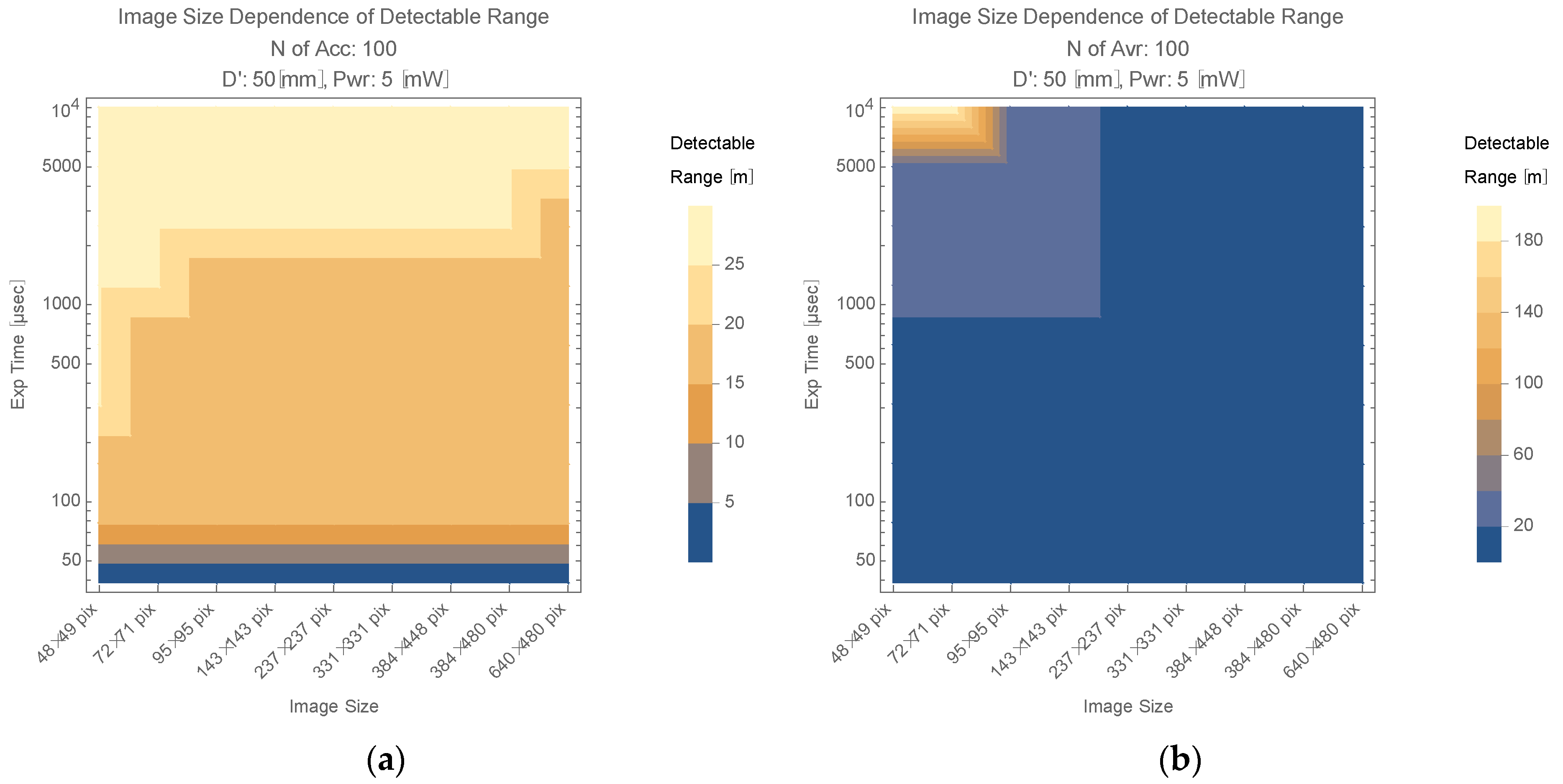
Figure 8 shows the simulation plot when the camera optics’ diameter D’ is 50 mm.
With the increase in the cameras optics’ diameter from 0.94 mm to 50 mm and accumulating 100 images, this image sensor potentially supports a 30 m detectable range in case of a 104 μsec exposure time (Figure 8a). Such performance would be realized with, e.g., a 10 cm size target and 15× zoom lens. When trimming down to an appropriate image size, Figure 8b shows this image sensor would support about a 200 m detectable range, based on the SNR discussion. Such performance would be realized with, e.g., a 1 m size target and 10× zoom lens. These types of image sensors would find middle/long range application such as powering over drones, vehicles and remote stations.

4.3.2. Beam Size (Beam Divergence) Control

When   A SC < A tr , Equation (A10) becomes F ( R ) =   A SC / A tr . If the distance to the target is long enough, A tr is approximated by Equation (A16). Knowing the distance to the target by ranging or information from a positioning system before operation (transmission) and controlling θ t so that F ( R ) is kept constant with respect to the distance, the determination equation of R (Equation (11)) is replaced by the following equation:
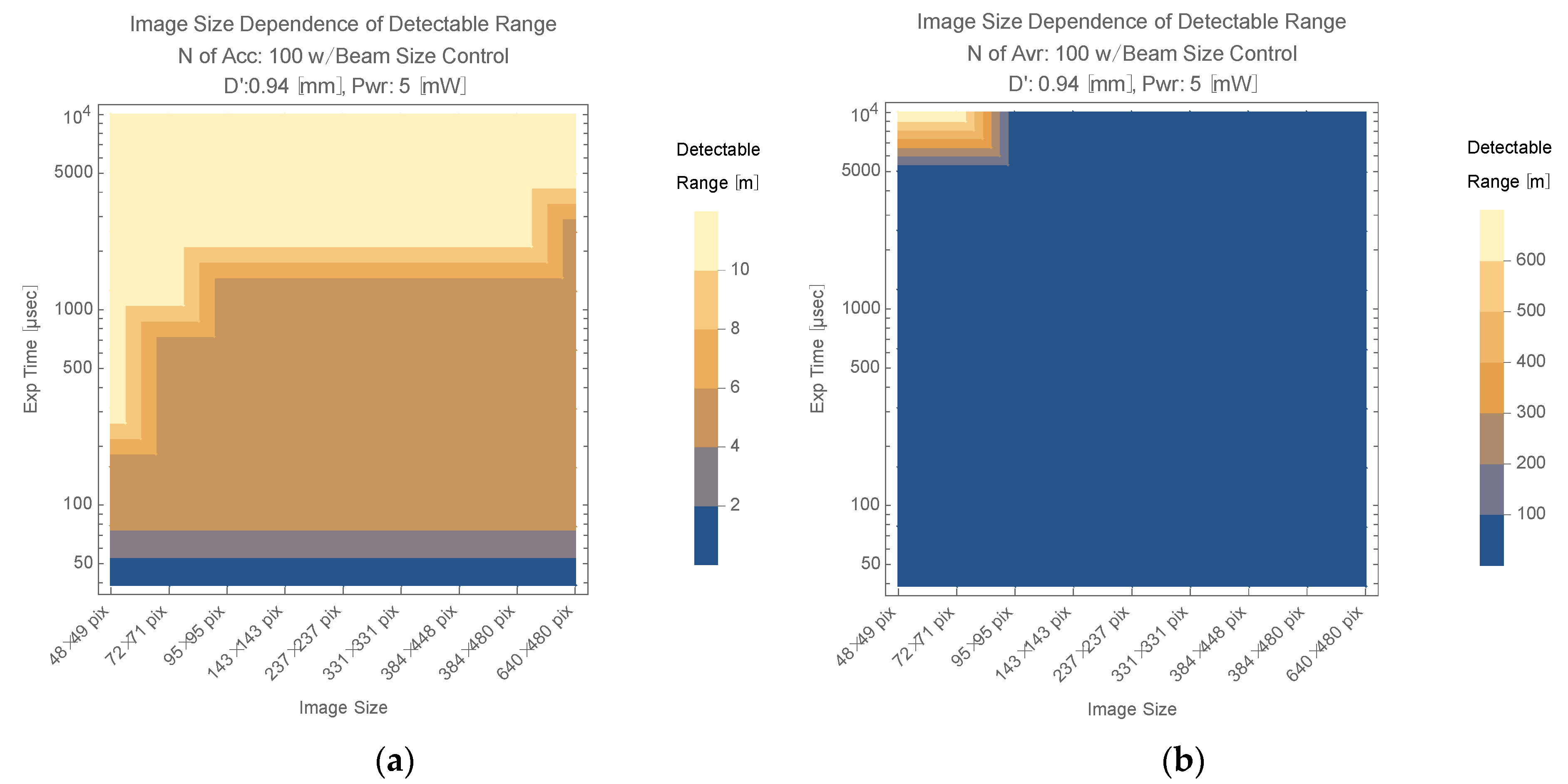
R 2 = R 2 ( D / D ) 2 / ( T FE T p n )
Figure 9 and Figure 10 show a simulation plot based on Equation (13). Figure 9 shows D’ = 0.94 mm case. In this case, the accumulation scheme and averaging scheme support about a 10 m and about a 600 m maximum detectable range, respectively. Comparing this 10 m detectable range of accumulation scheme with Figure 7a and Figure 8a, the maximum detectable range in each figure is similar (not so different). Considering the beam adjusting mechanism in the image sensor is necessary for beam size control, Figure 9a appears to not have enough advantage to allow for introducing such complexity to the image sensor. To achieve around a 10 m detectable range, increasing the diameter of the camera optics would be a simple and better strategy.
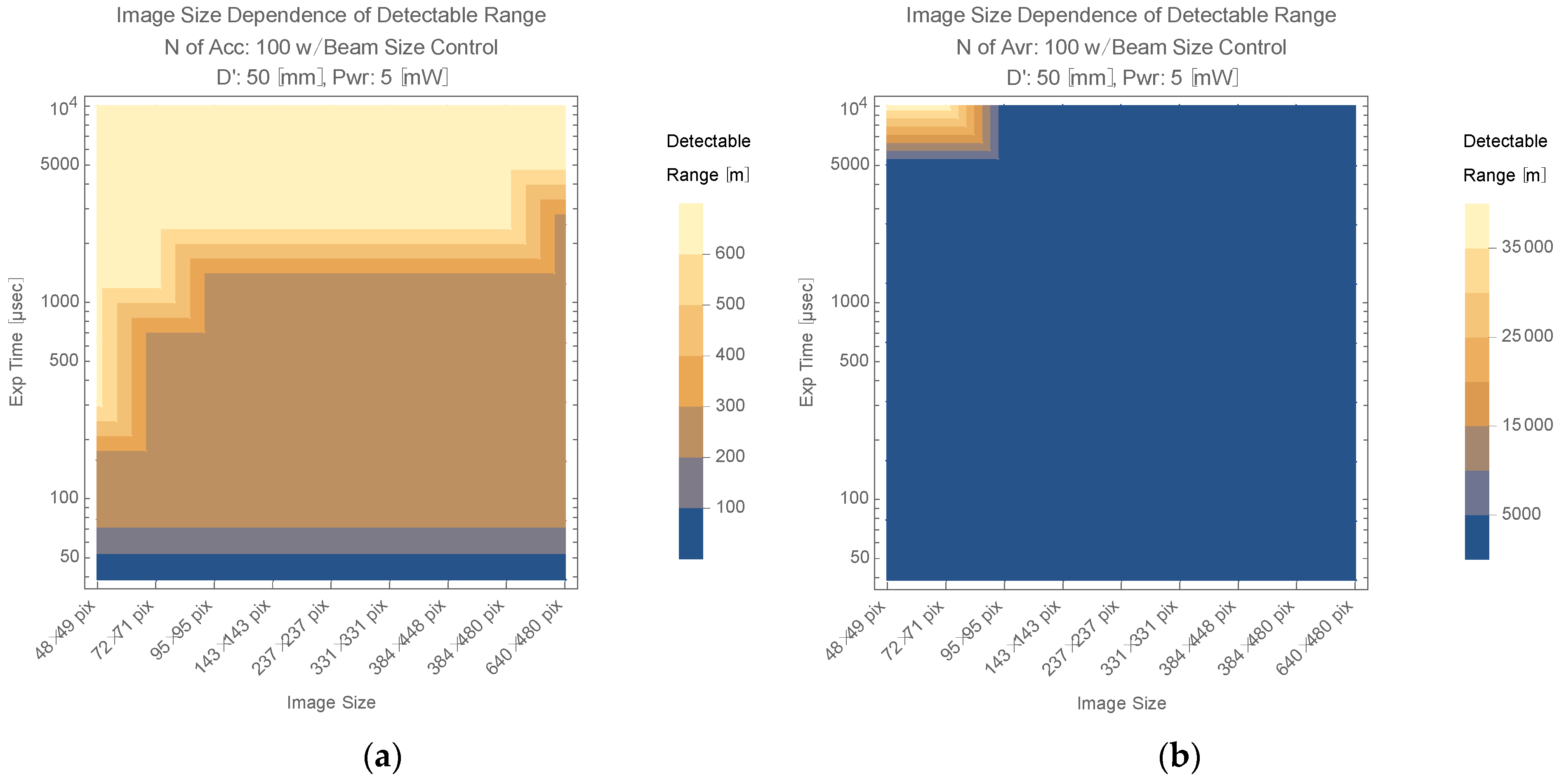
This situation becomes quite different in the long range case. Both Figure 9b and Figure 10a support about a 600 m maximum detectable range. Figure 10b, especially, supports about a 35 km with 50 mm diameter of camera lens and trimming down to the appropriate image size. Neither Figure 8 nor Figure 9a support such a long detectable range. For OWPT that supports a long range, such as several hundred meters or more, the detection of PV in various illuminating conditions would be a serious problem. These three figures (Figure 9b and Figure 10a,b) indicate that utilizing this image sensor with trimming down to an appropriate image size or controlling beam size would be solutions for such problem. These types of image sensors could find long range and large-scale applications, such as powering over large drones, vehicles and remote stations.

4.4. Effect of Background

Figure 6 shows that intensity on the Si/frost glass target is less than 1 μ W / cm 2 for P1 and less than 1   nW / cm 2 for P5. Therefore, if enough λ OFF intensity is contained in the background, this differential absorption image sensor does not need any active λ OFF illumination. In fact, during the experiments shown in Figure 3, the Si image was extracted and generated a differential image with enough SNR using only the room light of the laboratory or much stronger illumination from a white LED light. External illumination was an unnecessary disturbance in former studies; however, it functions as additional λ OFF illumination, which helps it to detect the target in this sensor. These aspects show the robustness of this differential absorption image sensor. On the other hand, leakage of λ OFF to the measurement of λ ON ( λ OFF leakage) degrades SNR. In the actual operation scene, the background spectrum would be wide enough to cover both λ ON and λ OFF , and there would be λ OFF leakage to the λ ON image. Such leakage should be subtracted as a background in the differential image generation process (software measure), or λ OFF leakage should be suppressed by inserting the λ OFF cut filter (hardware measure) in front of an image sensor device in the case that λ OFF leakage is near saturation level.

5. Conclusions

Concept validation is conducted for a differential absorption image sensor regarding optical wireless power transmission (OWPT). Since this utilizes a differential absorption image, the Si substrate which simulates PV is detected and its X, Y center coordinates and area are determined within acceptable accuracy compared with requirements derived for OWPT.
The experiment apparatus was a 5 mW, λ = 532   nm CW light source, RGB sensor of Intel’s Realsense D435 depth camera, whose optics diameter is calculated from D435′s data sheet [17] as 0.94 mm. For a stationary PV simulated by a 2-inch Si substrate at a distance of 104.5 cm, and when the image size is trimmed down to 48 × 49 px, this differential image sensor detects the Si image with an accuracy of ±1 px for center coordinates and less than 50 px for area. Considering 1 px is equivalent to 1.54 mrad in D435 and a 104.5 cm distance to the target, an Si image was acquired with an accuracy of ±1.6 mm for center coordinates and of ±128 mm2 for area, which are about 3.1% for the diameter and about 6.3% for the area. Performance limitation regarding target distance based on SNR discussions is shown much better in Figure 7. To reach these detectable range limits, there are two issues which should be considered. One is the resolution of the camera, and this would be improved by utilizing a high-resolution camera or zoom lens. The other is image size trimming. This would be aided by knowing the approximate position information from an external source and then trimming the acquired image down to an appropriate size. With the simple experiment apparatus, preliminary results of performance assessment were obtained.
Performance in detecting the target is further improved by image processing, such as trimming the size with respect to the target size, number of accumulation or averaging. Moreover, performance is improved by the increase in the effective diameter of camera optics and beam divergence control of the transmitter. The current status is a simulation based on preliminary experiments, and such performance enhancement would be verified in experiments with a more complex apparatus and under various illuminating conditions. Even though values regarding detectability criteria derived in this study depend on conditions of the experiment and its apparatus in this study, nevertheless, the methodology in this study is general and it easily derives new values accommodating a new experiment and its apparatus.
Thus, regarding active PV detection for OWPT, the feasibility of this image sensor was validated, and its potential was realized.

Author Contributions

Conceptualization, K.A. and T.M.; methodology, K.A and T.M.; formal analysis, K.A.; investigation, K.A.; data curation, K.A.; software, K.A. and K.M.; writing—original draft preparation, K.A.; writing—review and editing, T.M.; project administration, T.M.; funding acquisition, T.M. All authors have read and agreed to the published version of the manuscript.

Funding

This work was partially supported by the Tsurugi-Photonics Foundation (No. 20220502) and the Takahashi Foundation for Industrial and Economic Research (No. I2-003-13). In addition, part of this paper is based on the project commissioned based on the Mechanical Social Systems Foundation and Optoelectronic Industry and Technology Development Association (“Formulation of strategies for market development of optical wireless power transmission systems for small mobilities”).

Institutional Review Board Statement

Not applicable.

Informed Consent Statement

Not applicable.

Acknowledgments

We thank members of the T. Miyamoto Lab for discussion and assistance.

Conflicts of Interest

The authors declare no conflict of interest.

Appendix A. Estimation of Calibration Parameters

Appendix A.1. Estimation of γ Parameter

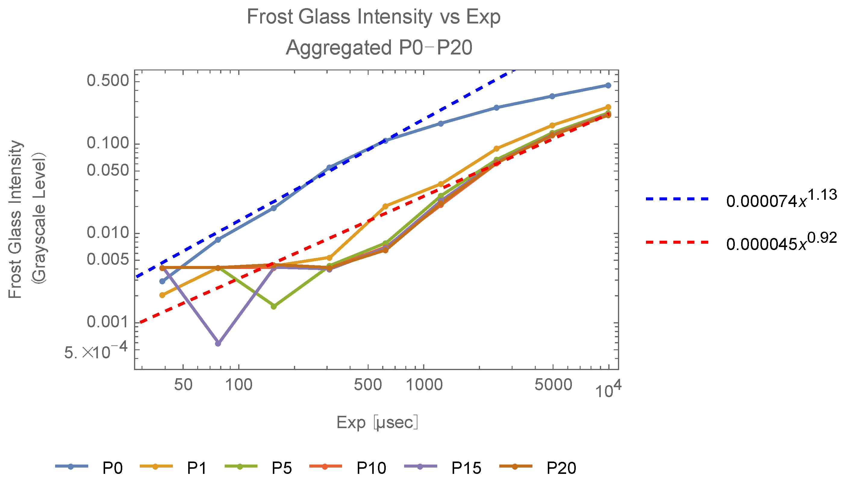
Light source beam power is 5 mW (CW) and the quantity of the accumulated intensity over exposure time (hereafter, this is also referred to as ‘intensity’), should be proportional to exposure time. The γ parameter of the applied camera is not published, and thus, the γ parameter is estimated by verification of the proportional relationship between exposure time and intensity, recorded on pixels in image data. Figure A1 shows the exposure time dependence of the grayscale level of a frost glass target illuminated by the light source. Data are plotted with the number of filter papers as a parameter.
In this paper, ‘with’ is abbreviated as ‘w/’ and ‘without’ as ‘w/o’. One hundred images are taken for every combination of parameter set of exposure time and the number of filter papers.
Each data point is the grayscale level of a pixel, which is the average of 100 images of mean intensity of a 48 × 49 pixel image. Since the Figure A1 plot is a log scale for both the vertical and horizontal axis, the slope of each plot represents the γ parameter. Each slope is not stable for a small grayscale level, and the saturation effect is visible for a large level, especially in the P0 plot.
Figure A1. Grayscale level dependence on exposure time.
Photonics 09 00861 g0a1
Even though grayscale level differs nearly 10 times between P0 and P1, P5, P10, P15 and P20, each estimation of the γ parameter using data from each plot’s linear region is close to one. Therefore, γ parameter correction is not applied in the following data analysis.

Appendix A.2. Estimation of Intensity Reduction Factor

  • Estimation of T p ( n )
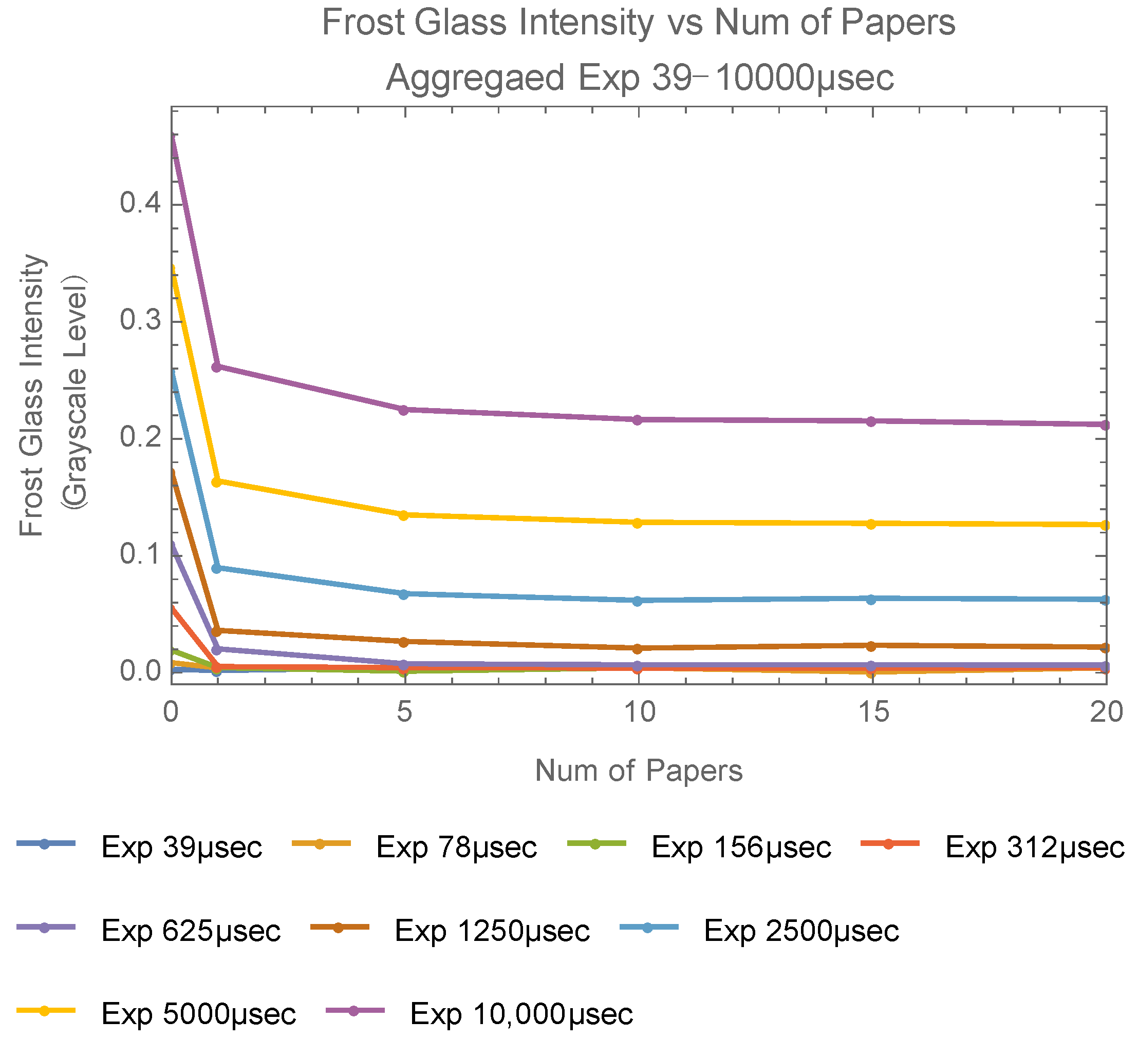
Setting the fly eye lens and varying the number of filter papers, the mean intensity of each acquired image is measured as grayscale intensity for exposure time (Exp) as a parameter (Figure A2).
Figure A2. Frost glass intensity.
Photonics 09 00861 g0a2
As the number of the filter papers increases, each grayscale level approaches a constant value. From Figure A2, this value is confirmed to be monotonically increasing with exposure time. This is regarded as the background. Let n be the number of filter papers and E ( n ) be intensity. E ( n ) is assumed to be expressed using attenuation factor T p ( n ) and by the flowing equation:
E ( n ) = [ E ( 0 ) E ( ) ] T p ( n ) + E ( )
Since each intensity value at the number of papers = 20 looks stably constant for each exposure time, these data are regarded as constant offsets and set as follows:
E ( ) = E ( 20 )
Then, Equation (A1) is modified as:
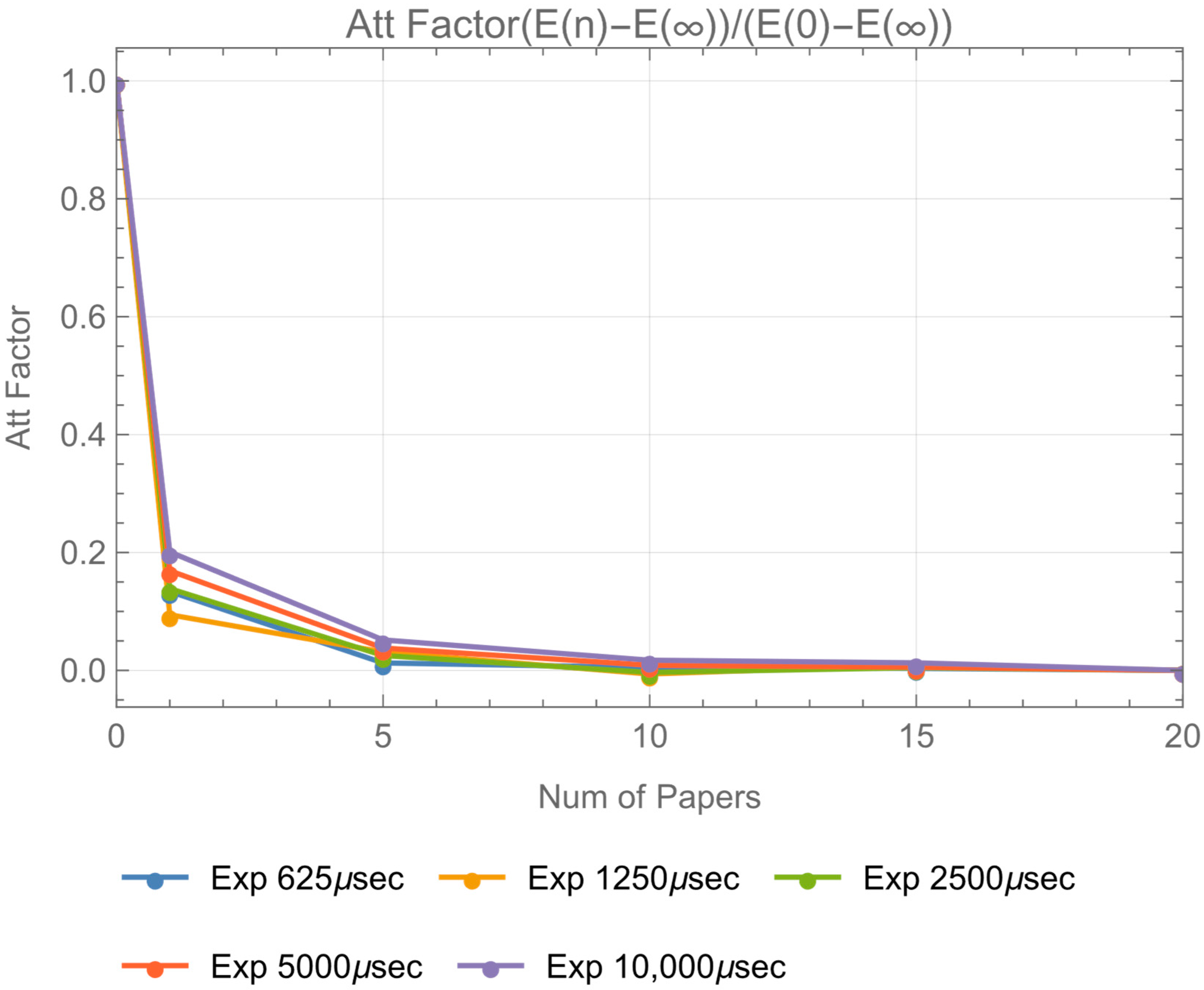
T p ( n ) = [ E ( n ) E ( 20 ) ] / [ E ( 0 ) E ( 20 ) ]
T p ( n ) is plotted for each exposure time in Figure 8. It should be noted that plotted data are limited within the Exp = 625 ,   1250 ,   250 ,   5000 ,   10 , 000   μ sec range, since, in Figure A1, frost glass intensity become stable only in this region.
Figure A3 is fitted by the following function, with a constant parameter β .
T p ( n ) = e β n
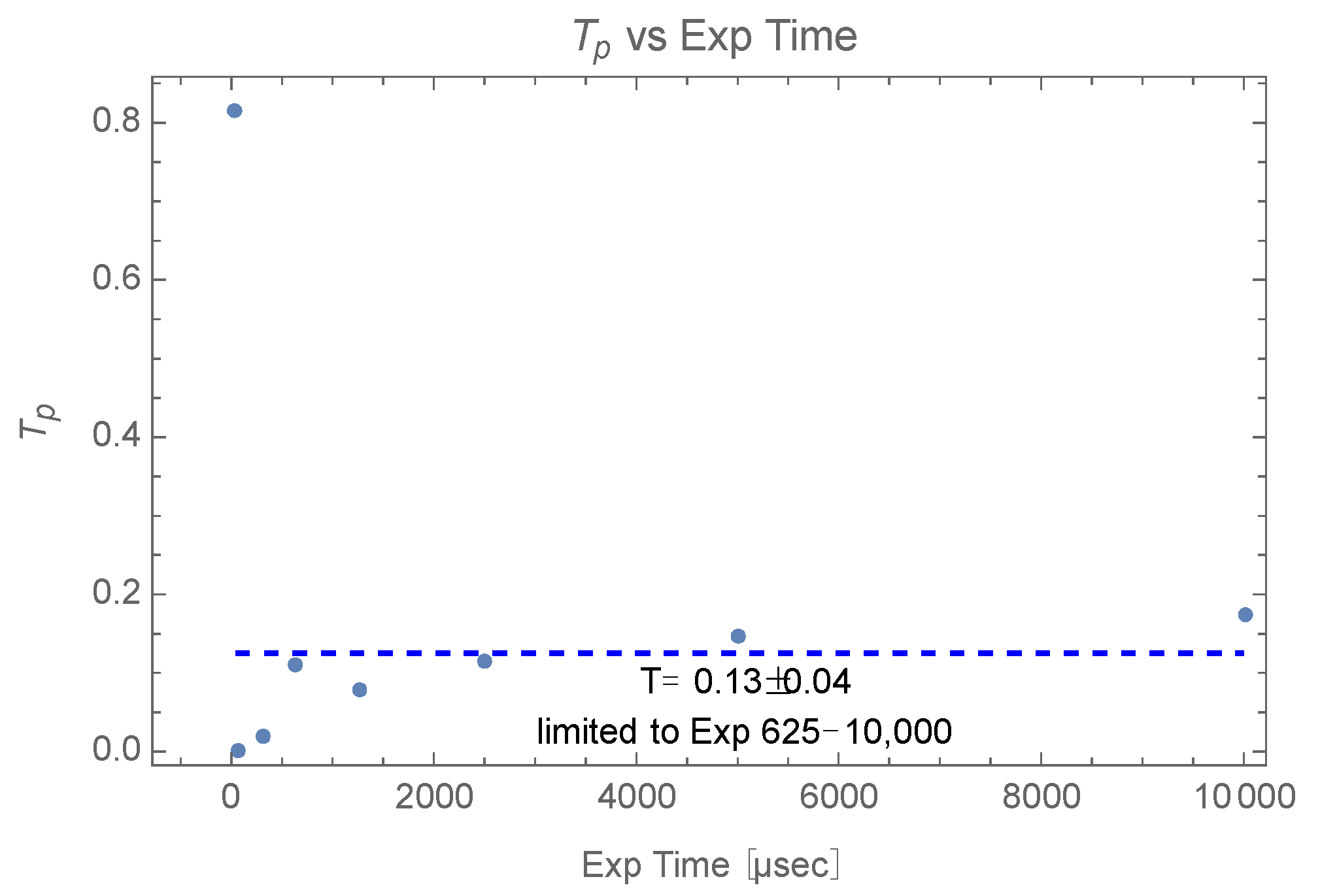
Let T p be T p e β , then T p ( n ) = T p n .  Figure A4 shows an estimation of T p ; it appears constant for exposure time, and its value is T p = 0.13 ± 0.04 .
Figure A3. Attenuation factor T p ( n ) .
Photonics 09 00861 g0a3
Figure A4. Estimation of T p .
Photonics 09 00861 g0a4
Therefore, T p ( n ) becomes T p ( n ) = ( 0.13 ) n . Even though T p value would tend to be smaller due to the saturation effect of P0 data, nonetheless, this provides a margin for the performance assessment of this image sensor.
  • Estimation of T FE  
T FE is expressed by the following equation:
T FE = [ E w / FE E Bg ] / [ E w / o   FE E Bg ]
E w / FE E Bg represents the background free intensity on an Si/frost glass target with the fly eye lens and filter papers. E w / o   FE E Bg represents the background free intensity on an Si/frost glass target with neither the fly eye lens nor the filter papers. E Bg is the 100 image average of mean intensity of a 48 × 49 pixel image with the light source OFF. Figure A5 shows the E w / FE / E Bg and E w / o   FE / E Bg plot for exposure time.
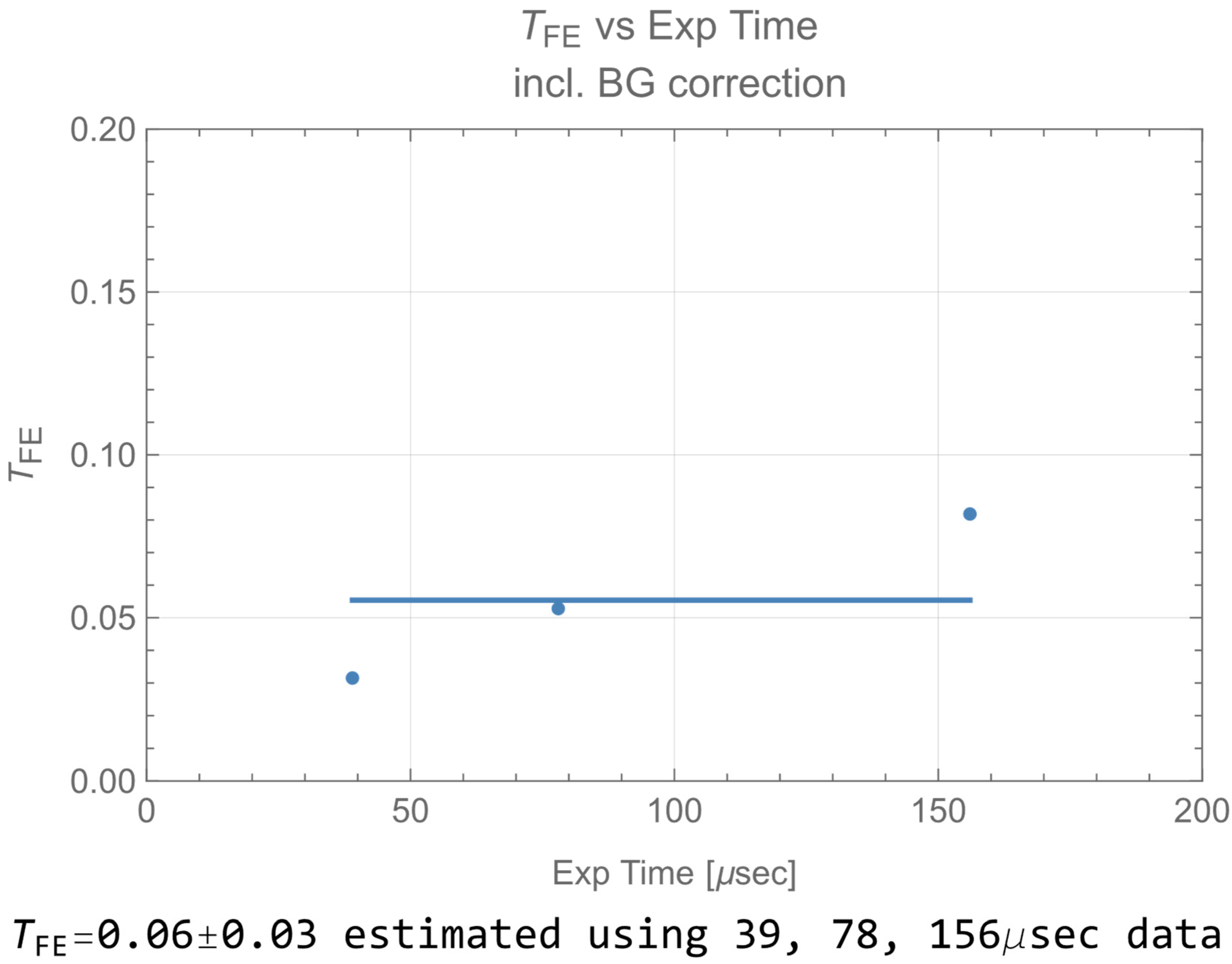
Looking into data of exposure   time 625   μ sec , whose intensity data are stable in Figure A1, Figure A5 shows that intensity on frost glass and background is almost equal regardless of the fly eye lens. The Figure 6 plot indicates that the value of E w / FE E Bg is quite small. As a result, T FE becomes ~ 0 / 0 , and the estimation is not successful. Thus, such data are difficult to use for estimation of T FE . Since usable data are limited whose SNR to background is larger, thus, only P0 and P0 w/FE data are used for the estimation of T FE . In Figure 6, P0 data look affected by saturation for exposure   time 312   μ sec . To avoid this saturation, T FE is estimated by data of exposure   time = 3,978,156   μ sec . The result is shown in Figure A6, and the estimation is T FE = 0.06 ± 0.03 . The value increases with exposure time due to the saturation effect of P0, P0 w/FE. This results in a larger estimation standard deviation. However, the larger estimation provides a margin for the performance assessment of this image sensor.
Figure A5. Frost glass intensity/background intensity.
Photonics 09 00861 g0a5
Figure A6. Estimated TFE.
Photonics 09 00861 g0a6

Appendix B. Differential Images and Binarized Images of Trimming Size 48 × 49 px, Exposure Time 10,000 μ sec
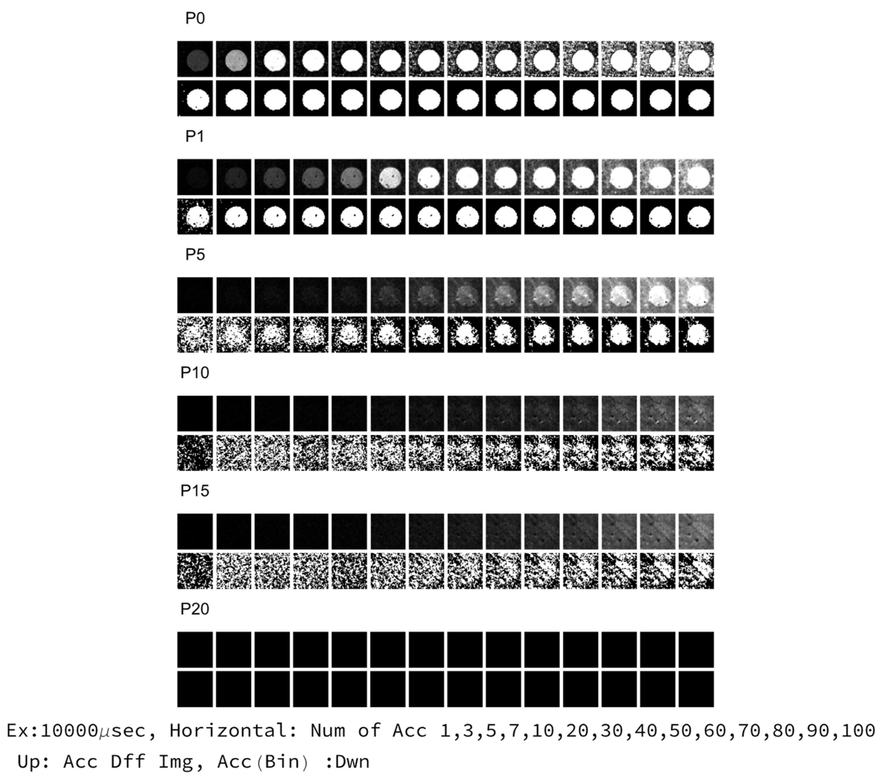
The upper row of Figure A7 represents the accumulated differential images Img Acc ( Exp , P ,   n ) , and the lower row is binarized image Img Bin ( Exp ,   P ,   n ) . The horizontal row represents changes in differential images and binarized images by variation in the number of accumulation (n: 1, 3, 5, 7, 10, 20, 30, 40, 50, 60, 70, 80, 90, 100). The vertical column represents changes by variation in the number of the filter papers (P: P0, P1, P5, P10, P15, P20). In case of n = 1, images are not accumulated.
Figure A7. Si image of 48 × 49 px, Exp 10,000 μ sec .
Photonics 09 00861 g0a7

Appendix C. Determination Error of X, Y Center Coordinates and Area (48 × 49 px Trimming Size)
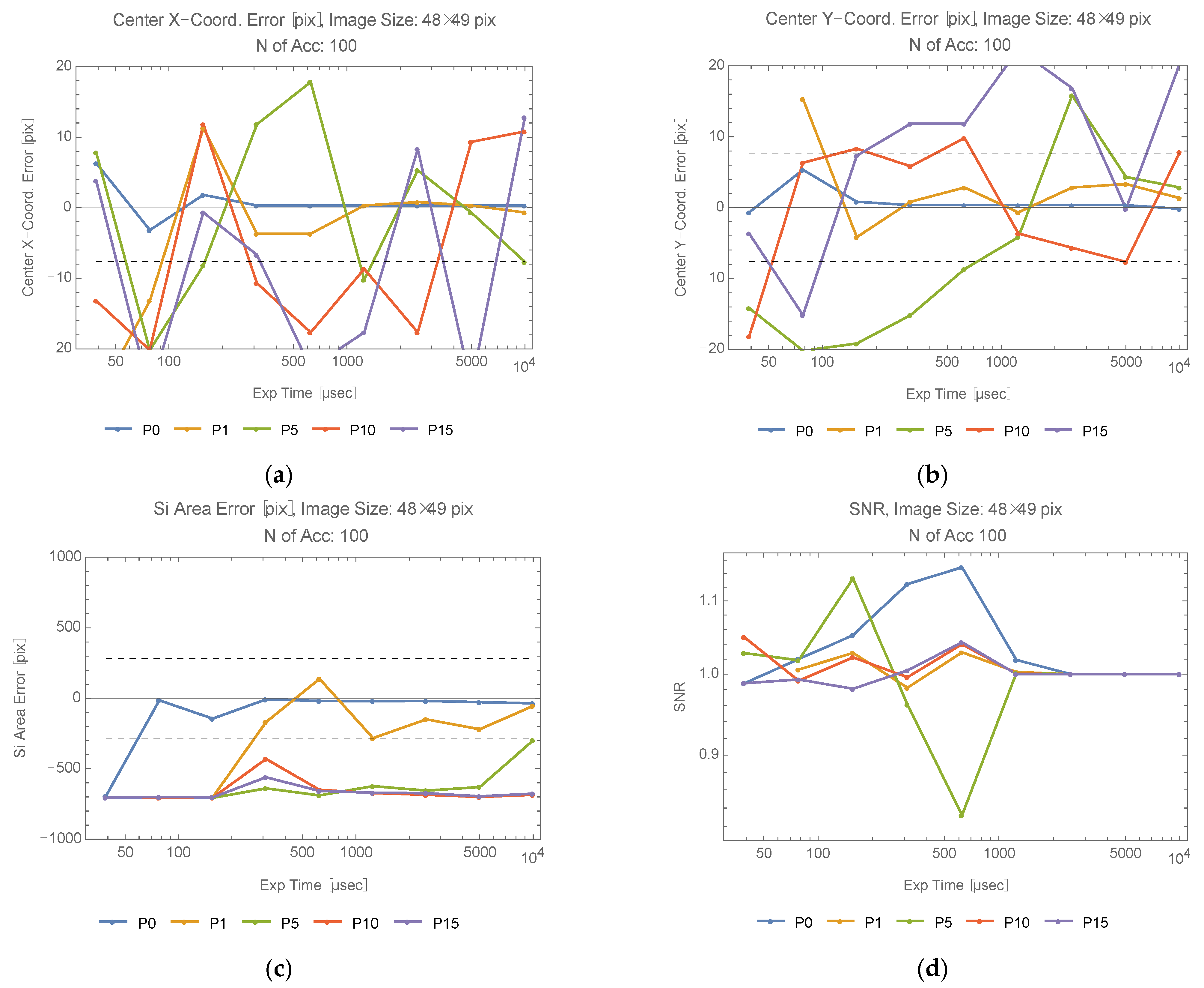
The determination error of the X, Y center coordinates and area are plotted (48 × 49 px trimming size) in Figure A8 and Figure A9. An SNR plot is included, as well. In both Figure A8 and Figure A9, the numbers of the filter papers are the parameters. The SNR approaches to one as the exposure time increases due to the saturation effect. In Figure A8, each X, Y center coordinate, area and SNR is calculated after accumulating 100 data points. In Figure A9, each point is the mean of the errors of 100 data with 1 σ error bar. SNR is also mean in Figure A9. Comparing Figure A8 and Figure A9, the averaging in Figure A9 appears more stable than the accumulation in Figure A8.
Figure A8. Center coordinate error, area error, SNR (100 accumulation): (a) Center X-coordinate error; (b) Center Y-coordinate error; (c) Si area error; (d) SNR.
Photonics 09 00861 g0a8
Figure A9. Center coordinate error, area error, SNR (100 averaging): (a) Center X-coordinate error; (b) Center Y-coordinate error; (c) Si area error; (d) SNR.
Photonics 09 00861 g0a9

Appendix D. Derivation of Equation (10)

Let the number of signal electrons and noise electrons be N s , N n , respectively. SNR is expressed by N s , N n .
SNR = N s / N n
Since N n is a function of exposure time, number of accumulations, internal noise parameter of camera and N s , SNR is determined by N s when the internal camera parameters, exposure time and number of accumulations are a fixed constant. Assume the incident beam is scattered by a Lambertian object. Let η Q : quantum efficiency of a sensor inside the camera, Δ σ / Δ Ω : differential cross section of the target, Δ ω : field of view of the camera (solid angle), I t : incident beam power density, η r : efficiency of camera optics, ρ : diffuse reflectivity of the target, hc / λ : photon energy of the incident beam, Exp :   exposure   time . From the definition of a differential cross section in the scattering process:
N s = ( λ / hc ) ρ I t η r η Q ( Δ σ / Δ Ω ) Δ ω Exp
Let P t : incident beam power, A tr : beam area at the target point, η t : efficiency of transmitter optics (including intensity reduction factor). I t Δ σ is written as follows:
I t Δ σ = Δ σ η t P t / A tr
Δ σ is written as Δ σ = A SC when the area of target A SC is smaller than the area of beam A tr , Δ σ = A tr when A tr > A SC . Thus,
I t Δ σ = P t η t F ( R )
F ( R ) { 1       ( if   A SC A TR ) A SC / A tr       ( if   A SC < A tr )
When the target is Lambertian, Δ Ω is evaluated as follows:
Δ Ω = 0 π / 2 2 π sin θ cos θ d θ = π
Let range to target:   R and the effective area of the receiver optics of the camera: A r .
Δ ω = A r / R 2
Therefore, N s is written as follows:
N s = ( λ / hc ) η r η t η Q P t F ( R ) ρ A r Exp / π R 2
Note that the intensity reduction factor T FE T p n is included in η t .
Assume two systems with different A r ,   R ,   η t provide the same SNR. Additionally, assume one system includes both one fly eye lens and n filter papers, and the other includes neither. The two systems are distinguished by adding a prime symbol to A r ,   R ,   η t . Then, N s of the two systems is equated.
η r η t η Q P t F ( R ) ρ A r Exp / π R 2 ( λ / hc ) = η t η t η Q P t F ( R ) ρ A r Exp / π R 2 ( λ / hc )
Assume   A SC < A tr and let θ t : transmitter beam divergence (half) angle. A tr is represented as follows:
A tr = π [ ( θ t R ) 2 + D 0 2 ] / 4
where D 0 represents the incident beam diameter at the transmitter. In many cases, it would be reasonable to assume ( θ t R ) 2 D 0 2 and A tr is approximated as follows:
A tr π ( θ t R ) 2 / 4
Regarding A r , it is expressed using the effective diameter of the receiver optics of the camera.
A r = π D 2 / 4
Therefore, R is expressed by the following equation, which is Equation (10), and this determines the detectable range with neither fly eye lens nor filter papers.
R 4 = R 4 ( D / D ) 2 / T FE T p n
This expression does not include any unknown parameters, such as η Q . All such unknowns are confined in parameters R ,   T FE ,   T p and n . Note that all of them are measured and estimated by the experiments.

References

  1. Wang, Z.; Zhang, Y.; He, X.; Luo, B.; Mai, R. Research and Application of Capacitive Power Transfer System: A Review. Electronics 2022, 11, 1158. [Google Scholar] [CrossRef]
  2. Wi-Charge. The Wireless Power Company. Available online: https://www.wi-charge.com (accessed on 9 May 2022).
  3. Baraskar, A.; Yoshimura, Y.; Nagasaki, S.; Hanada, T. Space Solar Power Satellite for the Moon and Mars Mission. J. Space Saf. Eng. 2022, 9, 96–105. [Google Scholar] [CrossRef]
  4. PowerLight Technologies. Available online: https://powerlighttech.com/ (accessed on 23 May 2022).
  5. Asaba, K.; Miyamoto, T. System Level Requirement Analysis of Beam Alignment and Shaping for Optical Wireless Power Transmission System by Semi–Empirical Simulation. Photonics 2022, 9, 452. [Google Scholar] [CrossRef]
  6. Setiawan Putra, A.W.; Kato, H.; Adinanta, H.; Maruyama, T. Optical Wireless Power Transmission to Moving Object Using Galvano Mirror. In Free-Space Laser Communications XXXII; Hemmati, H., Boroson, D.M., Eds.; SPIE: Bellingham, WA, USA, 2020; p. 50. [Google Scholar] [CrossRef]
  7. Setiawan Putra, A.W.; Kato, H.; Maruyama, T. Infrared LED Marker for Target Recognition in Indoor and Outdoor Applications of Optical Wireless Power Transmission System. Jpn. J. Appl. Phys. 2020, 59, SOOD06. [Google Scholar] [CrossRef]
  8. Sovetkin, E.; Steland, A. Automatic Processing and Solar Cell Detection in Photovoltaic Electroluminescence Images. ICA 2019, 26, 123–137. [Google Scholar] [CrossRef] [Green Version]
  9. Imai, H.; Watanabe, N.; Chujo, K.; Hayashi, H.; Yamauchi, A.A. Beam-Tracking Technology Developed for Free-Space Optical Communication and Its Application to Optical Wireless Power Transfer. In Proceedings of the 4th Optical Wireless and Fiber Power Transmission Conference (OWPT2022), Yokohama, Japan, 18–21 April 2022; p. OWPT-5-01. [Google Scholar]
  10. XiaoJie, M.; Tomoyuki, M. Safety System of Optical Wireless Power Transmission by Suppressing Light Beam Irradiation to Human Using Camera. In Proceedings of the 3rd Optical Wireless and Fiber Power Transmission Conference (OWPT2021), Online, 19–22 April 2021; p. OWPT-8-03. [Google Scholar]
  11. He, T.; Yang, S.-H.; Zhang, H.-Y.; Zhao, C.-M.; Zhang, Y.-C.; Xu, P.; Muñoz, M.Á. High-Power High-Efficiency Laser Power Transmission at 100 m Using Optimized Multi-Cell GaAs Converter. Chin. Phys. Lett. 2014, 31, 104203. [Google Scholar] [CrossRef] [Green Version]
  12. Liu, Y.; Miyamoto, T. Numerical Analysis of Multi-Particle Mie Scattering Characteristics for Improvement of Solar Cell Appearance in OWPT System. In Proceedings of the 3rd Optical Wireless and Fiber Power Transmission Conference (OWPT2021), Online, 19–22 April 2021; p. OWPT-P-01. [Google Scholar]
  13. Kawashima, N.; Takeda, K.; Yabe, K. Application of the Laser Energy Transmission Technology to Drive a Small Airplane. Chin. Opt. Lett. 2007, 5, S109–S110. [Google Scholar]
  14. Differential Absorption Lidar|Elsevier Enhanced Reader. Available online: https://reader.elsevier.com/reader/sd/pii/B9780123822253002048?token=ACBBE2F8761774F5628FC13C0F6B8E339140949E50BF9DE9F5063F95873CC081FB2353E862E10CA4576416252562C600&originRegion=us-east-1&originCreation=20220824035349 (accessed on 22 August 2022).
  15. Dual-Wavelength Measurements Compensate for Optical Interference. 7 May 2004. Available online: https://www.biotek.com/resources/technical-notes/dual-wavelength-measurements-compensate-for-optical-interference/ (accessed on 24 August 2022).
  16. Herrlin, K.; Tillman, C.; Grätz, M.; Olsson, C.; Pettersson, H.; Svahn, G.; Wahlström, C.G.; Svanberg, S. Contrast-Enhanced Radiography by Differential Absorption, Using a Laser-Produced X-Ray Source. Invest Radiol 1997, 32, 306–310. [Google Scholar] [CrossRef] [PubMed]
  17. Intel. Intel® RealSenseTM D400 Series Data Sheet. Available online: https://www.intelrealsense.com/wp-content/uploads/2022/05/Intel-RealSense-D400-Series-Datasheet-April-2022.pdf?_ga=2.148303735.1760514517.1667622478-1298527653.1667622478/ (accessed on 23 August 2022).
  18. Intel® RealSenseTM. Intel® RealSenseTM Depth and Tracking Cameras. Available online: https://www.intelrealsense.com/sdk-2/ (accessed on 23 August 2022).
  19. Open, CV. Available online: https://opencv.org/ (accessed on 23 August 2022).
  20. Python.org. Welcome to Python.org. Available online: https://www.python.org/ (accessed on 24 August 2022).
  21. Wolfram Mathematica: Modern Technical Computing. Available online: https://www.wolfram.com/mathematica/ (accessed on 15 August 2022).
  22. Otsu, N. A Threshold Selection Method from Gray-Level Histograms. IEEE Trans. Syst. Man Cybern. 1979, 9, 62–66. [Google Scholar] [CrossRef] [Green Version]
  23. Binarize Wolfram Language Documentation. Available online: https://reference.wolfram.com/language/ref/Binarize.html.en?source=footer (accessed on 15 August 2022).
  24. Tang, J.; Matsunaga, K.; Miyamoto, T. Numerical Analysis of Power Generation Characteristics in Beam Irradiation Control of Indoor OWPT System. Opt. Rev. 2020, 27, 170–176. [Google Scholar] [CrossRef]
  25. Mori, N. Design of Projection System for Optical Wireless Power Transmission Using Multiple Laser Light Sources, Fly-Eye Lenses, and Zoom Lens. In Proceedings of the 1st Optical Wireless and Fiber Power Transmission Conference (OWPT2019), Yokohama, Japan, 23–25 April 2019; p. OWPT-4-02. [Google Scholar]
  26. Katsuta, Y.; Miyamoto, T. Design, Simulation and Characterization of Fly-Eye Lens System for Optical Wireless Power Transmission. Jpn. J. Appl. Phys. 2019, 58, SJJE02. [Google Scholar] [CrossRef]
  27. GPS.gov: GPS Accuracy. Available online: https://www.gps.gov/systems/gps/performance/accuracy/ (accessed on 9 May 2022).
  28. Quuppa. Indoor Positioning System. Available online: https://www.quuppa.com/indoor-positioning-system/ (accessed on 9 May 2022).
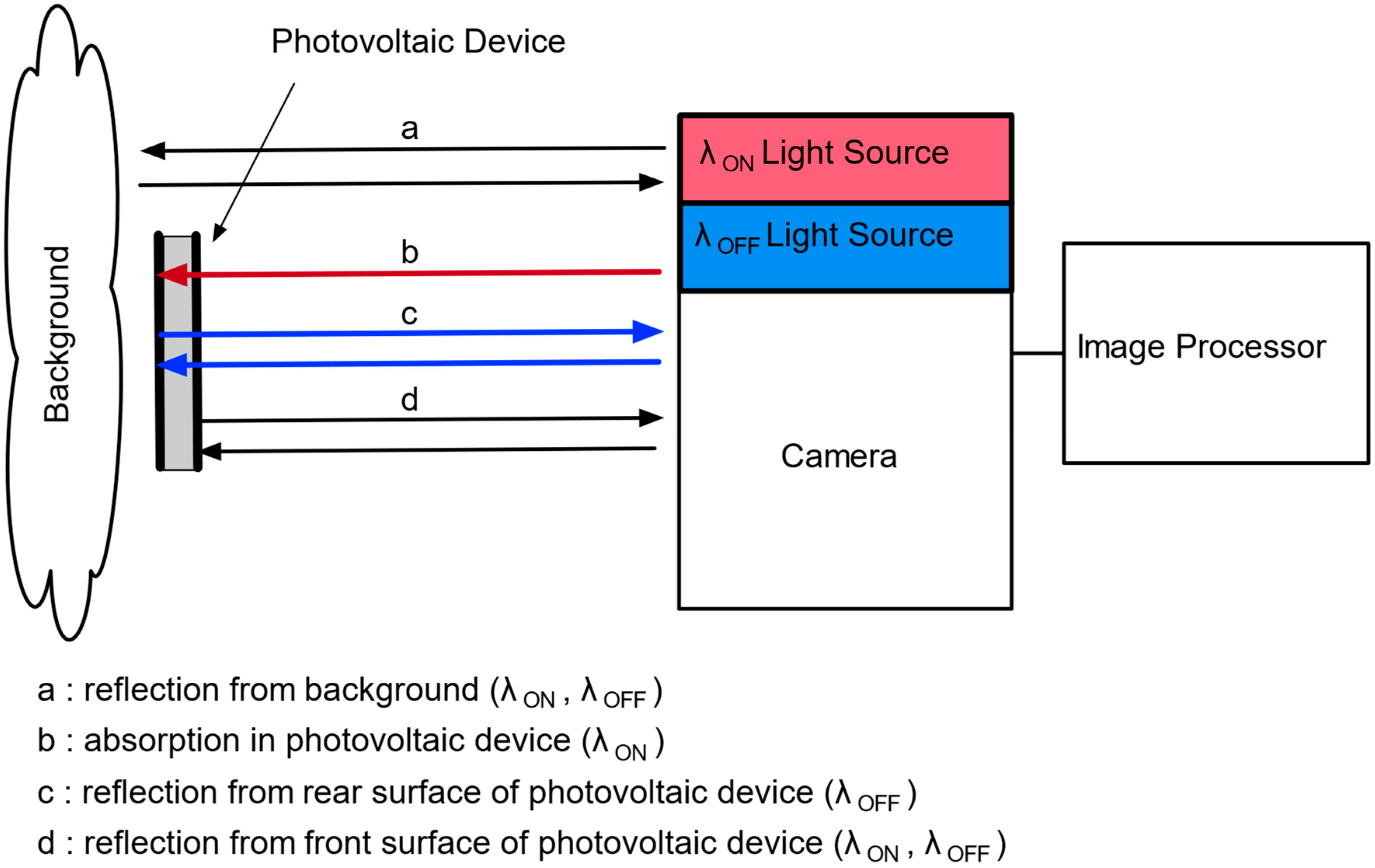
Figure 1. Principle of differential absorption image sensor.
Photonics 09 00861 g001
Figure 2. Generation of differential absorption image.
Photonics 09 00861 g002
Figure 3. Configurations of experiments: (a) Experiment apparatus; (b) Setup of experiments.
Photonics 09 00861 g003
Figure 4. Examples of acquired raw data (P0, Acc = 1, Exp: 10,000 μ sec , image size 640 × 480 px): (a) Raw data with frost glass sample; (b) Raw data with Si sample.
Photonics 09 00861 g004
Figure 5. Generation of the Si image by binarization (P0, Acc = 1, Exp: 10,000 μsec, image size 48 × 49 px): (a) Binarized image of differential absorption image; (b) Boundary rectangle of the extracted Si image superimposed on the original differential image.
Photonics 09 00861 g005
Figure 6. Intensity on Si/frost glass.
Photonics 09 00861 g006
Figure 7. Detectable range plot: (a) 100 accumulation; (b) 100 averaging.
Photonics 09 00861 g007
Figure 8. Detectable range plot for 50 mm camera optics’ diameter: (a) 100 accumulation; (b) 100 averaging.
Photonics 09 00861 g008
Figure 9. Detectable range plot for a 0.94 mm receiver diameter with beam size control: (a) 100 accumulation; (b) 100 averaging.
Photonics 09 00861 g009
Figure 10. Detectable range plot for a 50 mm receiver diameter with beam size control: (a) 100 accumulation; (b) 100 averaging.
Photonics 09 00861 g010
Publisher’s Note: MDPI stays neutral with regard to jurisdictional claims in published maps and institutional affiliations.