Abstract
A relative humidity sensor was fabricated by exploiting an evanescent wave (EW) on a U-bent tapered plastic optical fiber (POF) coated with zinc oxide (ZnO) nanorods. The POF was tapered manually using a polishing method to a diameter of 0.5 mm, a length of 5 cm, and a radius of 5 cm. ZnO nanorods were synthesized using a hydrothermal method and grown on the POF by a seeding process for 12 h. A significant response of the sensor was observed when the sensor was exposed to 35 to 90%RH due to the intense chemisorption process and changeable relative index in the POF. The sensitivity and resolution of the sensor have been improved by factors of 1.23 and 2.18, respectively, compared to the conventional tapered POF sensor without ZnO coating. Besides, the ZnO-coated sensor also exhibited better repeatability properties in terms of output voltage when exposed to 35 to 90%RH for three repeated measurements. The obtained results revealed that the proposed new POF sensor has an excellent sensing performance as an RH sensor in terms of sensitivity, repeatability, and stability properties.
1. Introduction
Precise humidity measurements are vital for many applications including food, agriculture, and electronic industries. Depending on the level of sophistication required, commercially available humidity sensors can be inaccurate and irresponsive. They are susceptible to electromagnetic interference and have a limited range of operation [1]. Accurate humidity sensors for real-time measurement are needed for quality and safety control in many industries. Fiber-optic technology can be exploited for this purpose. Fiber-optic sensors have been used to sense humidity using various approaches. For instance, loop resonator-based relative humidity (RH) sensors managed to achieve a sensitivity as high as 0.2053 dBm/%RH, but they are sensitive to changes in their looped touching region [2]. Micro-ball [3], and micro-bottle [4] resonators have also been used to detect RH, but extra precautions should always be taken to ensure the resonators are positioned properly for the proper coupling of light. On the other hand, there is also an increasing interest in nanostructure materials for sensing applications due to their huge advantages in electrical and optical properties. This growing attention among researchers is motivated by advances in humidity sensor technology based on nanostructure materials, including advantages such as small size, immunity against electromagnetic waves, rapid response and recovery time, and high sensitivity [5]. There have been significant numbers of studies on optical RH sensors based on nanostructure materials such as zinc oxide (ZnO) [6], tungsten disulfide (WS2) [7], tin oxide (SnO2) [8], titanium dioxide (TiO2) [9], polyethyleneimine (PEI), and graphene oxide (GO) [10]. Among them, ZnO has been widely used for RH sensing as it is a high refractive index (RI) material (RI = 2.008), in which the surface adsorption of water molecules onto the ZnO leads to changes in the optical properties of ZnO [11]. By using an optical fiber for RH sensing, the complex RI can be modified by coating the optical fiber with the nanostructure material [12].
ZnO has distinctive optical and electrical features such as thermal stability, good electrical conductivity with a high exciting binding energy (60 meV), a large bandgap energy (3.37 eV), and reactive surfaces for chemisorption of molecular water at ambient temperature [13]. In particular, ZnO nanorods have shown a good response to humidity in the literature [14,15,16,17]. One of the main features of ZnO nanorods is that their effective RI changes during exposure to humidity, causing higher light scattering loss via the nanorods’ structure. This effect contributes to changes in light transmission and increases the sensitivity to humidity [18].
In RH sensing, plastic optical fiber (POF) has recently attracted attention from researchers due to benefits such as a large diameter, high numerical aperture, low attenuation in the visible areas, more satisfactory manufacturing, and excellent mechanical strength [19,20]. Furthermore, POF is flexible and smooth and has a lower softening temperature, allowing flexibility and tapering. With specific attention to intensity modulation schemes and low-cost solutions, POF-based RH sensors offer valuable alternatives to traditional technologies. When the light scatters through the sensing region, the RI of the coating varies with the humidity level due to evanescent absorption, and, as a result, the intensity of the output light will be modified [21,22,23]. To enhance the environmental impact of the RI, optical fiber cladding was removed using chemical and mechanical etching [24] and heat-pulling methods [25], followed by a tapered section coated with metal oxides [26,27].
Previously, researchers have demonstrated relative humidity (RH) sensing using a straight POF [5,28,29,30] and U-shape POF [31,32]. Jindal et al. found that the U-shape POF showed better performance in RH sensing compared to the straight POF [33]. The interaction between the fiber mode and the external environment generates more light leakage from the fiber as the bending radius is reduced. This feature increases sensitivity significantly, but if the fiber’s refractive loss is too high, the output signal at the receiving end will be low [34]. In other work, the U-shape POF was tapered to enhance the sensitivity of various sensors [34,35,36,37]. However, there are no previous reports on tapered U-shape POF coated with ZnO nanorods via the hydrothermal method for RH sensing. In this paper, ZnO nanorods were synthesized using hydrothermal methods and coated onto a tapered POF before bending it to a radius of 5 cm for RH sensing. To the best of our knowledge, it is the first time the ZnO nanorod-coated tapered U-shape POF (Z-UPOF) has been investigated for RH sensing. In addition, a red light-emitting diode was used in this work to investigate the sensitivity of the RH sensor. The present work demonstrated the higher sensitivity of the Z-UPOF compared with the uncoated sensor. This approach provides an efficient, easy, and cost-effective method for RH sensing.
2. Preparation of ZnO Nanorods Coated Tapered U-Shape POF
The POF used consists of polymethylmethacrylate (PMMA) as the core and fluorinated polymers as the cladding. It has a diameter of 1.0 mm, a core refractive index of 1.492, and a cladding refractive index of 1.402. At first, a blade was used to cut a 5 cm long section of fiber jacket protector from the center of the fiber. Then, the tapered POF was prepared by removing the cladding layer using acetone, followed by polishing the core fiber using sandpaper of 1000 grit. Micrometers were used on a regular basis to measure the stripped area, to ensure the waist diameter of the tapered fibers was approximately 0.5 mm.
ZnO nanorods were then grown on the prepared tapered U-shape POF. Initially, a seeding process was conducted to form a nucleation center for the growth of ZnO nanorods. ZnO seed particles were synthesized by dissolving 0.0044 g of zinc acetate dihydrate [Zn(O2CCH3)2·2H2O] (Emsure®, Darmstadt, Germany) in 20 mL of ethanol [C2H5OH] (95%) to form a 1 mM solution under constant stirring for 30 min at a temperature of 50 °C. After the solution temperature reached ~35 °C, another 20 mL of ethanol was added to the solution. In order to increase the pH of the solution to alkali, 0.0003 g of sodium hydroxide [NaOH] (Emsure®, Darmstadt, Germany) was added to 20 mL of ethanol at a temperature of 50 °C and stirred slowly. Then, the solution was stored for 3 h in a water bath at a temperature of 60 °C. Next, the tapered POF was dipped into the ZnO seed solution for 30 s and placed on a hotplate, with a temperature of 70 °C, followed by the evaporation of the solvents for 2 min to secure the seeds. This process was repeated 10 times to provide an optimal seed distribution on the tapered POF surface. Then, the sample was annealed at 70 °C for 3 h.
Next, 1.4875 g of zinc nitrate hexahydrate [Zn(NO3)2·6H2O] (Sigma-Aldrich, Germany) and 0.7 g of hexamethylenetetramine [(CH2)6N4] (Sigma-Aldrich, Darmstadt, Germany) were dissolved in 500 mL of deionized water (DI) to form 10 mM solutions. The seeded POFs were then placed in a 200 mL synthesis solution and dried in an oven at 90 °C. The synthesis solution was replaced every 5 h with a new solution to maintain a continuous growth of ZnO nanorods on the tapered POF. The ZnO nanorods were grown for 12 h on the tapered U-shape POF and were rinsed with DI water several times. This seeding process was similar to that reported in the reference [38]. Then, the proposed sensor was inserted into a plastic holder to form the fiber into a U-shape structure. The tapered U-shape POF coated with ZnO nanorods was labeled Z-UPOF, while the tapered U-shape POF without coating was labeled N-UPOF in this work. Figure 1 shows the image of the Z-UPOF with a bending radius of 5 cm.
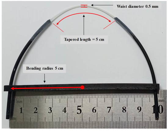
Figure 1.
The image of prepared U-shape tapered POF.
The ZnO nanorods on the tapered U-shape POF were then characterized. Figure 2a shows the scanning electron microscope (SEM) image. It confirmed that the structure of ZnO is nanorods based on the rod structure and consists of many superfine nanorods on the POF. The magnification was set at 2.39 KX to observe the ZnO structures coated on the Z-UPOF. Energy dispersive X-ray (EDX) analysis with an operating voltage of 10 keV was carried out on the Z-UPOF to identify the chemical elements as shown in Figure 2b. The analysis revealed that the topcoat layer on the POF consisted of zinc (78.99%) and oxygen (21.01%), which verified the sensing material for relative humidity sensing is ZnO.
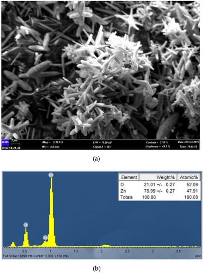
Figure 2.
ZnO nanorods on tapered U-shape POF (a) SEM image (b) EDX elemental analysis.
3. Experimental Setup and Arrangement
The experimental setup for RH sensing in this work is shown in Figure 3. Throughout the experiment, a hygrometer was fixed on the controlled chamber (0.13 m × 0.9 m × 0.6 m) wall as a reference to the actual chamber RH level. One tip of the sensor (Z−UPOF/N−UPOF) was connected to the red LED and the other tip of the sensor was connected to the phototransistor to perform RH sensing. The power supply Arduino Uno +5 V was used to operate the LED and the phototransistor, while a computer was used to monitor the data of humidity sensing. The red LED wavelength of 650 nm was used to access the optical fiber effects on light transmission through the fiber and the optical power was converted into an electrical signal using a phototransistor IF-D92 (Industrial Fiber Optics, Tempe, AZ, USA). During the exposure of the sensor to the relative humidity, the temperature inside the controlled chamber was kept constant at 24 °C. Previous studies have been published examining the relative humidity of 40–70% to solve the issue of the spread of viruses and bacteria and provide an optimum comfortable working environment [18]. This range is in accordance with the Malaysia Industry Code of Practice on Indoor Air Quality (2010) [39]. In addition, a higher value, measured up to 90%RH, helps keep electronic parts from corroding, which can be a fire risk in closed spaces [2]. Thus, in this work, the range between 35%RH and 90%RH was chosen to tailor these requirements. In this work, N-UPOF and Z-UPOF were exposed to RH in the range of 35% to 90%. To accommodate the lowest RH levels in this measurement, silica gel was used to lower the RH level to 35%. Then, wet wipes were substituted inside the chamber to raise the RH level to 90%. This experiment was recorded for every 5% of RH level starting from 35%RH and repeated three times to ensure the reliability of both sensors.
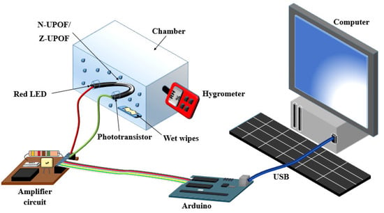
Figure 3.
Experimental set-up for RH sensing.
4. Result and Discussion
The repeatability properties of N-UPOF and Z-UPOF are shown in Figure 4. This measurement was conducted three times between 35% and 90%RH. The time interval to collect the data for each measurement was 3 min. It can be observed that the output voltages of the N-UPOF and the Z-UPOF decreased as the RH level increased. The maximum repeatability percentages (MR%) for N-UPOF and Z-UPOF were approximately 16% and 8%, respectively. Hence, the higher MR% in N-UPOF contributed to the irregular output voltage shift (Figure 4a), while the output voltages of Z-UPOF showed better consistency (Figure 4b). In addition, Z-UPOF produced a higher output voltage range of 1.56–2.61 V in comparison with the N-UPOF (2.13–2.90 V). This difference can be caused by the variation of the effective RI and the changes of light incident on the ZnO nanorods [12]. These results suggest that ZnO nanorods allow more absorption of water particles to induce more changes in evanescent wave (EW) with respect to the amount of humidity adsorption to achieve good repeatability.
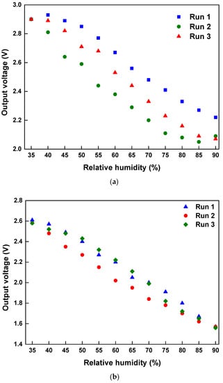
Figure 4.
The repeatability properties of (a) N-UPOF and (b) Z-UPOF.
Hysteresis curves of N-UPOF and Z-UPOF sensors are displayed in Figure 5. This test was carried out by observing the sensing responses for the adsorption and desorption processes of the RH in the range of 35 to 90%RH for both sensors. The time interval between the two processes was set to 3 min for both sensors. Based on Figure 5a,b, the highest calculated humidity hysteresis (γH) contributed by N-UPOF and Z-UPOF were approximately 11.34% and 6.89%, respectively. The humidity hysteresis was calculated using γH = ± (ΔVmax/VFS)100%, where ΔVmax is the maximum voltage variance at a certain humidity level and VFS is the full-scale output of voltage [40]. The small hysteresis produced in a sensor results in higher reliability and measurement consistency [41]. For N-UPOF, it was found that the voltage level was lower during the desorption process, from 90% to 85% of the RH level. This is due to the non-existence of ZnO nanorods which causes a slow sensing response during the transition between the adsorption and desorption processes, thus exhibiting a further voltage reduction from 90%RH to 85%RH. However, at 85%RH, the output voltage starts to increase back in response to the decrement in %RH. As seen, Z-UPOF has lower humidity hysteresis; thus, the Z-UPOF sensor produced better measurement consistency in the voltage stability compared to the N-UPOF due to the coated material on the tapered U-shape POF where the hydrophilicity of ZnO plays a role during water molecule absorption [42].
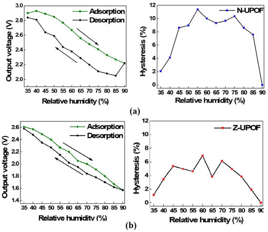
Figure 5.
Hysteresis curve of (a) N-UPOF and (b) Z-UPOF.
Output voltages against RH for N-UPOF and Z-UPOF sensors are shown in Figure 6. The output voltages for both sensors decreased linearly with the increment of the RH levels. The sensitivity of the sensor is defined as the slope of the curve between the %RH and output voltage [43]. It can be observed that the sensitivity of the N-UPOF is 0.0158 V/%RH with a linearity of more than 99%, while the sensitivity of Z-UPOF is 0.0194 V/%RH with a linearity of more than 99%. This can be caused by high surface area, high photosensitivity, catalyst-free growth, large area uniform production, and the high sensitivity of ZnO nanorods [17]. Besides that, the rapid adsorption of water molecules on the surface can also be attributed to the porous structure of ZnO nanorods on the POF. This surface adsorption process also modulates the optical properties of the ZnO nanorods. As the RH level increases, additional water molecules on the surfaces of the ZnO nanorods on the Z-UPOF were absorbed. This behavior was also reported by Liu et al., where increasing water molecules lead to an increase in the effective surrounding medium refractive index as well as in the coefficient of absorption of ZnO nanorod surfaces, leading both to a larger leakage and light absorption within the ZnO nanorods structures [30]. Table 1 summarizes the sensitivity of the RH sensing application in the other related work.
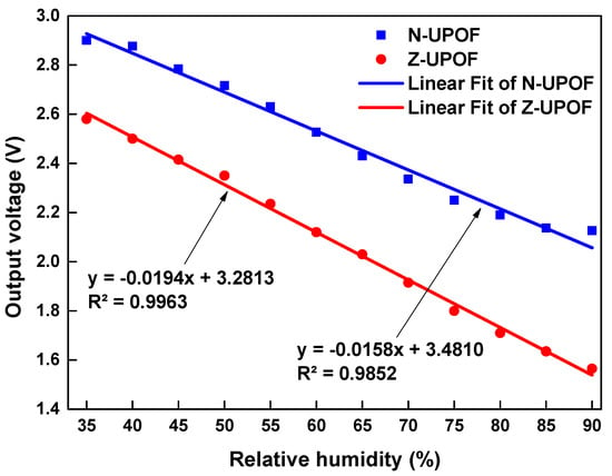
Figure 6.
Output voltages against relative humidity for N−UPOF and Z−UPOF sensors.

Table 1.
Comparison with other %RH sensor.
Both sensors (N-UPOF and Z-UPOF) were tested for voltage stability by exposure to 90%RH where the output voltages were recorded continuously for 60 s on the first day and after 10 days. Figure 7 displays N-UPOF and Z-UPOF voltage stability for the 1st and 10th days. It was observed that the output voltage for N-UPOF after 10 days was similar to the 1st day, while the output voltage stability for Z-UPOF was slightly reduced after 10 days. It was revealed that the output voltage of Z-UPOF was slightly reduced because of the degradation of ZnO nanorods after 10 days, where this phenomenon has also been observed in reference [42]. However, the sensitivity of Z-UPOF on the 10th day remained at 0.0194 V/%RH, as illustrated in Figure 6.
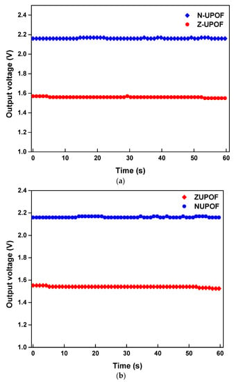
Figure 7.
N-UPOF and Z-UPOF voltage stability during (a) the 1st day and (b) 10th day.
Table 2 summarizes the characteristics of N-UPOF and Z-UPOF sensors. Both sensors (N-UPOF and Z-UPOF) showed superiority in terms of sensing performance with > 99% linearity. The standard deviation is the amount of change from the mean value of repeatable measurement data, while the resolution is the minimum concentration of the suggested sensor that gives an output measurement by dividing the standard deviation with sensitivity [45]. The standard deviation and resolution were found to be 0.0619 V and 3.1958%RH for the Z-UPOF, while N-UPOF obtained 0.1157 V and 7.3233%RH, respectively. This is because the Z-UPOF enhanced the interaction between the sensing region and the environment, thus significantly increasing the sensing response [5]. It is found that the sensitivity and resolution of the Z-UPOF sensor improved by a factor of 1.23 and 2.18, respectively compared to the N-UPOF.

Table 2.
Characteristics of N-UPOF and Z-UPOF sensor.
5. Conclusions
A simple fiber optic for RH sensing applications was successfully developed using ZnO nanorods coated on tapered U-shape POF. The Z-UPOF structure greatly improved the sensing performance as compared to the N-UPOF while reducing the complexity of the fabrication process. The sensitivity and resolution of the Z-UPOF sensor improved by factors of 1.23 and 2.18, respectively, compared to the N-UPOF.
Author Contributions
Conceptualization, S.H.J. and H.R.A.R.; methodology, S.H.J. and M.A.M.J.; validation, M.H.J.; formal analysis, T.Z.C.; investigation, S.H.J.; resources, M.Y. and S.W.H.; data curation, S.H.J.; writing—original draft preparation, S.H.J.; writing—review and editing, S.W.H. and T.Z.C.; supervision, S.W.H.; project administration, M.H.J. and H.H.M.Y.; funding acquisition, S.W.H. All authors have read and agreed to the published version of the manuscript.
Funding
This research was funded by Malaysian Ministry of Higher Education through Fundamental Research Grant Scheme (Grant No: FP114-2020).
Institutional Review Board Statement
Not applicable.
Informed Consent Statement
Not applicable.
Data Availability Statement
The data presented in this study are available on request from the corresponding author. The data are not publicly available due to privacy concerns.
Conflicts of Interest
The authors declare no conflict of interest.
References
- Peng, Y.; Zhao, Y.; Chen, M.-Q.; Xia, F. Research Advances in Microfiber Humidity Sensors. Small 2018, 14, 1800524. [Google Scholar] [CrossRef]
- Jali, M.H.; Rahim, H.R.A.; Johari, M.A.M.; Hamid, S.S.; Yusof, H.H.M.; Thokchom, S.; Wang, P.; Harun, S.W. Optical characterization of different waist diameter on microfiber loop resonator humidity sensor. Sens. Actuators A Phys. 2019, 285, 200–209. [Google Scholar] [CrossRef]
- Mallik, A.K.; Liu, D.; Kavungal, V.; Wu, Q.; Farrell, G.; Semenova, Y. Agarose coated spherical micro resonator for humidity measurements. Opt. Express 2016, 24, 21216–21227. [Google Scholar] [CrossRef]
- Md Johari, M.A.; Abdul Khudus, M.I.M.; Bin Jali, M.H.; Noman, A.A.; Harun, S.W. Effect of Size on Single and Double Optical Microbottle Resonator Humidity Sensors. Sens. Actuators A Phys. 2018, 284, 286–291. [Google Scholar] [CrossRef]
- Azad, S.; Sadeghi, E.; Parvizi, R.; Mazaheri, A.; Yousefi, M. Sensitivity optimization of ZnO clad-modified optical fiber humidity sensor by means of tuning the optical fiber waist diameter. Opt. Laser Technol. 2017, 90, 96–101. [Google Scholar] [CrossRef]
- Irawati, N.; Rahman, H.; Ahmad, H.; Harun, S. A PMMA microfiber loop resonator based humidity sensor with ZnO nanorods coating. Measurement 2016, 99, 128–133. [Google Scholar] [CrossRef]
- Luo, Y.; Chen, C.; Xia, K.; Peng, S.; Guan, H.; Tang, J.; Lu, H.; Yu, J.; Zhang, J.; Xiao, Y.; et al. Tungsten disulfide (WS_2) based all-fiber-optic humidity sensor. Opt. Express 2016, 24, 8956–8966. [Google Scholar] [CrossRef] [PubMed]
- Ascorbe, J.; Corres, J.; Matias, I.R.; Arregui, F.J. High sensitivity humidity sensor based on cladding-etched optical fiber and lossy mode resonances. Sens. Actuators B Chem. 2016, 233, 7–16. [Google Scholar] [CrossRef]
- Faruki, M.J.; Ab Razak, M.Z.; Azzuhri, S.R.; Rahman, M.T.; Soltanian, M.R.K.; Brambilla, G.; Rahman, B.M.A.; Grattan, K.T.V.; De La Rue, R.; Ahmad, H. Effect of titanium dioxide (TiO2) nanoparticle coating on the detection performance of microfiber knot resonator sensors for relative humidity measurement. Mater. Express 2016, 6, 501–508. [Google Scholar] [CrossRef]
- Hernaez, M.; Acevedo, B.; Mayes, A.G.; Melendi-Espina, S. High-performance optical fiber humidity sensor based on lossy mode resonance using a nanostructured polyethylenimine and graphene oxide coating. Sens. Actuators B Chem. 2019, 286, 408–414. [Google Scholar] [CrossRef]
- Chakrabarti, S.; Banerjee, P.; Mitra, P.; Roy, A. Zinc oxide–based nanomaterials for environmental applications. Handb. Smart Photocatalytic Mater. 2020, 73–107. [Google Scholar] [CrossRef]
- Lokman, M.Q.; Rahim, H.R.B.A.; Harun, S.W.; Hornyak, G.L.; Mohammed, W.S. Light backscattering (e.g. reflectance) by ZnO nanorods on tips of plastic optical fibres with application for humidity and alcohol vapour sensing. Micro Nano Lett. 2016, 11, 832–836. [Google Scholar] [CrossRef]
- Kulkarni, S.S.; Shirsa, M.D. Optical and structural properties of zinc oxide nanoparticles. Int. J. Adv. Res. Phys. Sci. 2015, 2, 14–18. [Google Scholar]
- Yusof, H.H.M.; Harun, S.W.; Dimyati, K.; Bora, T.; Mohammed, W.S.; Dutta, J. Optical dynamic range maximization for humidity sensing by controlling growth of zinc oxide nanorods. Photonics Nanostruct. Fundam. Appl. 2018, 30, 57–64. [Google Scholar] [CrossRef]
- Azad, S.; Sadeghi, E.; Parvizi, R.; Mazaheri, A. Fast response relative humidity clad-modified multimode optical fiber sensor with hydrothermally dimension controlled ZnO nanorods. Mater. Sci. Semicond. Process. 2017, 66, 200–206. [Google Scholar] [CrossRef]
- Jali, M.H.; Rahim, H.R.A.; Yusof, H.H.M.; Johari, A.; Thokchom, S.; Harun, S.W. Humidity Effects on the Growth of ZnO Nanorods using Hydrothermal Method. J. Phys. Conf. Ser. 2020, 1552, 012004. [Google Scholar] [CrossRef]
- Harith, Z.; Batumalay, M.; Irawati, N.; Harun, S.W.; Ahmad, H.; Hu, T. ZnO nanorod-coated tapered plastic fiber sensors for relative humidity. Opt. Commun. 2020, 473, 125924. [Google Scholar] [CrossRef]
- Yusof, H.H.M.; Harun, S.W.; Dimyati, K.; Bora, T.; Sterckx, K.; Mohammed, W.S.; Dutta, J. Low-Cost Integrated Zinc Oxide Nanorod-Based Humidity Sensors for Arduino Platform. IEEE Sens. J. 2018, 19, 2442–2449. [Google Scholar] [CrossRef]
- Batumalay, M.; Harun, S.; Ahmad, F.; Nor, R.; Zulkepely, N.; Ahmad, H. Study of a fiber optic humidity sensor based on agarose gel. J. Mod. Opt. 2014, 61, 244–248. [Google Scholar] [CrossRef]
- Teng, C.; Jing, N.; Yu, F.; Zheng, J. Investigation of a Macro-Bending Tapered Plastic Optical Fiber for Refractive Index Sensing. IEEE Sens. J. 2016, 16, 7521–7525. [Google Scholar] [CrossRef]
- Vijayan, A.; Fuke, M.; Hawaldar, R.; Kulkarni, M.; Amalnerkar, D.; Aiyer, R. Optical fibre based humidity sensor using Co-polyaniline clad. Sens. Actuators B Chem. 2008, 129, 106–112. [Google Scholar] [CrossRef]
- Batumalay, M.; Harun, S.W.; Irawati, N.; Ahmad, H.; Arof, H. A Study of Relative Humidity Fiber-Optic Sensors. IEEE Sens. J. 2014, 15, 1945–1950. [Google Scholar] [CrossRef]
- Fuke, M.V.; Kanitkar, P.; Kulkarni, M.; Kale, B.B.; Aiyer, R.C. Effect of particle size variation of Ag nanoparticles in Polyaniline composite on humidity sensing. Talanta 2010, 81, 320–326. [Google Scholar] [CrossRef]
- Mulyanti, B.; Abdurrahman, F.; Pawinanto, R.E.; Heri, A.; Sugandi, G. Fabrication of Polymer Optical Fiber as Intrinsic Optical Sensor Using Etching Technique. Adv. Sci. Lett. 2017, 23, 1310–1313. [Google Scholar] [CrossRef]
- Rahman, H.; Harun, S.; Yasin, M.; Phang, S.; Damanhuri, S.; Arof, H.; Ahmad, H. Tapered plastic multimode fiber sensor for salinity detection. Sens. Actuators A Phys. 2011, 171, 219–222. [Google Scholar] [CrossRef]
- Divagar, M.; Gowri, A.; John, S.; Sai, V.V.R. Graphene oxide coated U-bent plastic optical fiber based chemical sensor for organic solvents. Sens. Actuators B Chem. 2018, 262, 1006–1012. [Google Scholar] [CrossRef]
- Rajan, G.; Mathews, S.; Farrell, G.; Semenova, Y. A liquid crystal coated tapered photonic crystal fiber interferometer. J. Opt. 2010, 13, 015403. [Google Scholar] [CrossRef][Green Version]
- Corres, J.M.; Arregui, F.J.; Matías, I.R. Sensitivity optimization of tapered optical fiber humidity sensors by means of tuning the thickness of nanostructured sensitive coatings. Sens. Actuators B Chem. 2007, 122, 442–449. [Google Scholar] [CrossRef]
- Harith, Z.; Irawati, N.; Rafaie, H.A.; Batumalay, M.; Harun, S.W.; Nor, R.; Ahmad, H. Tapered Plastic Optical Fiber Coated with Al-Doped ZnO Nanostructures for Detecting Relative Humidity. IEEE Sens. J. 2014, 15, 845–849. [Google Scholar] [CrossRef]
- Liu, Y.; Zhang, Y.; Lei, H.; Song, J.; Chen, H.; Li, B. Growth of well-arrayed ZnO nanorods on thinned silica fiber and application for humidity sensing. Opt. Express 2012, 20, 19404–19411. [Google Scholar] [CrossRef]
- Guo, Z.; Chu, F.; Fan, J.; Zhang, Z.; Bian, Z.; Li, G.; Song, X. Study of macro-bending biconical tapered plastic optical fiber for relative humidity sensing. Sens. Rev. 2019, 39, 352–357. [Google Scholar] [CrossRef]
- Jagtap, S.; Rane, S.; Arbuj, S.; Rane, S.; Gosavi, S. Optical fiber based humidity sensor using Ag decorated ZnO nanorods. Microelectron. Eng. 2018, 187–188, 1–5. [Google Scholar] [CrossRef]
- Jindal, R.; Tao, S.; Singh, J.P.; Gaikwad, P. High dynamic range fiber optic relative humidity sensor. Opt. Eng. 2002, 41, 1093–1096. [Google Scholar] [CrossRef]
- Wang, S.; Zhang, D.; Xu, Y.; Sun, S.; Sun, X. Refractive Index Sensor Based on Double Side-Polished U-Shaped Plastic Optical Fiber. Sensors 2020, 20, 5253. [Google Scholar] [CrossRef]
- Wandermur, G.; Rodrigues, D.; Allil, R.; Queiroz, V.; Peixoto, R.; Werneck, M.; Miguel, M. Plastic optical fiber-based biosensor platform for rapid cell detection. Biosens. Bioelectron. 2014, 54, 661–666. [Google Scholar] [CrossRef]
- Punjabi, N.; Satija, J.; Mukherji, S. Evanescent Wave Absorption Based Fiber-Optic-Cascading of Bend and Tapered Geometry for Enhanced Sensitivity. In Sensing Technology: Current Status and Future Trends III; Springer: Cham, Switzerland, 2015; pp. 25–45. [Google Scholar]
- Tan, A.J.Y.; Ng, S.M.; Stoddart, P.R.; Chua, H.S. Theoretical Model and Design Considerations of U-Shaped Fiber Optic Sensors: A Review. IEEE Sens. J. 2020, 20, 14578–14589. [Google Scholar] [CrossRef]
- Rahim, H.R.B.A.; Manjunath, S.; Fallah, H.; Thokchom, S.; Harun, S.W.; Mohammed, W.S.; Hornyak, L.G.; Dutta, J. Side coupling of multiple optical channels by spiral patterned zinc oxide coatings on large core plastic optical fibers. Micro Nano Lett. 2016, 11, 122–126. [Google Scholar] [CrossRef]
- Arifin, N.A.; Denan, Z. An analysis of indoor air temperature and relative humidity in office room with various external shading devices in Malaysia. Procedia-Soc. Behav. Sci. 2015, 179, 290–296. [Google Scholar] [CrossRef]
- Parangusan, H.; Bhadra, J.; Ahmad, Z.; Mallick, S.; Touati, F.; Al-Thani, N. Capacitive type humidity sensor based on PANI decorated Cu–ZnS porous microspheres. Talanta 2020, 219, 121361. [Google Scholar] [CrossRef]
- Arunachalam, S.; Izquierdo, R.; Nabki, F.J.S. Low-hysteresis and fast response time humidity sensors using suspended functionalized carbon nanotubes. Sensors 2019, 19, 680. [Google Scholar] [CrossRef] [PubMed]
- Ulfa, M.; Nisa, D.; Prasetyoko, D. Investigating the hydrophilicity of zinc oxide nanoparticles using xylene and water for ibuprofen adsorption. J. Chem. Technol. Metall. 2021, 56, 761–768. [Google Scholar]
- Sikarwar, S.; Yadav, B. Opto-electronic humidity sensor: A review. Sens. Actuators A Phys. 2015, 233, 54–70. [Google Scholar] [CrossRef]
- Wang, Y.; Wang, J.; Shao, Y.; Liao, C.; Wang, Y. Highly sensitive surface plasmon resonance humidity sensor based on a polyvinyl-alcohol-coated polymer optical fiber. Biosensors 2021, 11, 461. [Google Scholar] [CrossRef] [PubMed]
- Jali, M.H.; Rahim, H.R.; Johari, M.A.; Yusof, H.H.; Ahmad, A.; Thokchom, S.; Dimyati, K.; Harun, S.W. Humidity sensing using microfiber-ZnO nanorods coated glass structure. Optik 2021, 238, 166715. [Google Scholar] [CrossRef]
- Zain, H.A.; Jali, M.H.; Rahim, H.R.A.; Johari, A.M.; Yusof, H.H.M.; Thokchom, S.; Yasin, M.; Harun, S.W. ZnO nanorods coated microfiber loop resonator for relative humidity sensing. Opt. Fiber Technol. 2020, 54, 102080. [Google Scholar] [CrossRef]
- Zhang, Y.; Hou, Y.; Liu, W.; Zhang, H.; Zhang, Y.; Zhang, Z.; Guo, J.; Liu, J.; Zhang, L.; Tan, Q.-L. A Cost-Effective Relative Humidity Sensor Based on Side Coupling Induction Technology. Sensors 2017, 17, 944. [Google Scholar] [CrossRef]
- Harith, Z.; Batumalay, M.; Irawati, N.; Harun, S.; Arof, H.; Ahmad, H. Relative humidity sensor employing tapered plastic optical fiber coated with seeded Al-doped ZnO. Optik 2017, 144, 257–262. [Google Scholar] [CrossRef]
Publisher’s Note: MDPI stays neutral with regard to jurisdictional claims in published maps and institutional affiliations. |
© 2022 by the authors. Licensee MDPI, Basel, Switzerland. This article is an open access article distributed under the terms and conditions of the Creative Commons Attribution (CC BY) license (https://creativecommons.org/licenses/by/4.0/).