Abstract
A tunable microwave-pulse-generation scheme is proposed and demonstrated by employing an actively mode-locked optoelectronic oscillator (OEO) based on a microwave photonic filter (MPF). The MPF mainly consists of a phase-shifted fiber Bragg grating (PS-FBG) and a phase modulator. The microwave pulse trains with variable repetition rates are achieved by injecting an external signal, of which the frequencies are equal to an integer multiple of the free spectrum range (FSR) of the OEO. The multi-mode oscillation mechanism is discussed in detail theoretically and experimentally. A microwave pulse train with a central frequency of 9.25 GHz and repetition rate of 1.68 MHz is demonstrated by setting the injecting signal frequency to be the same with the FSR of the OEO. A tunable center frequency of the microwave pulses from 5.47 GHz to 18.91 GHz can be easily generated by tuning the laser frequency benefit from adopting the MPF. Furthermore, the microwave pulses with different pulse periods of 297.62 ns, 198.69 ns, and 148.81 ns are also realized by harmonic mode-locking. The proposed tunable microwave-pulse-generation method has potential applications in the pulse Doppler radar and communications.
1. Introduction
The generation of microwave signals with high frequency and wide tuning range is increasingly needed in the fields of radar, wireless communication, and electronic warfare [1,2,3,4]. Conventionally, the microwave signals generated by electronical technology face the contradiction between the phase noise and the frequency tunability due to the electronic bottlenecks [5,6,7]. The microwave photonics technology paves an alternative way for microwave signal generation [8,9], in which the optoelectronic oscillator (OEO) has attracted extensive research attentions due to its feature of wideband tunable microwave signals generation with ultra-low phase noise [10,11,12,13]. Up to now, a variety of typical OEOs have been reported to extend the frequency-tunable range or the purity of the generated signal. The broadband frequency-tunable OEOs based on a microwave photonic filter constructed by a phase-modulation and phase-shifted Bragg gratings or SBS effects are discussed in [14]. The dual-loop OEO is proposed to balance the contradiction between the phase noise and the spur suppression ratio [15]. More and more technologies, such as injection locking [16,17] or phase-locked loop [18,19], appear later to purify and stable the generated signal. The key point for the low phase noise is the high-quality factor benefit from the low optical loss of the fiber delay line, which on the contrary deteriorates the long-term stability and the size of the OEO limits their practical applications. More compact OEOs based on the whispering gallery mode resonators have attracted huge attention recently as replacements for the several kilometer fibers [20]. However, the above schemes mainly focus on the high-quality single-frequency microwave signal generation limited to the mode construction time, which cannot meet the demands for special signal waveform applications, especially for radar systems.
Recently, various OEO techniques for radar systems have been proposed. For example, a compact integrable linearly chirped microwave waveform generator, based on a recirculating phase-modulation loop and OEO sections, has been used as a key building block in photonic synthetic aperture radar systems [21]. The Fourier domain mode-locked OEO [22,23,24] has been proposed to generate a linearly frequency-modulated signal with a large time-bandwidth product, which can effectively alleviate the contradiction between the detecting range and the range resolution for radar. Further, a novel type of OEO based on the time-domain mode-locking [24,25,26,27,28,29] has been demonstrated to generate coherent pulse trains with short duration and variable repetition rates, which is beneficial for a pulsed Doppler radar to improve the velocity and range resolution. The so-called actively mode-locked OEO is realized by injecting an external signal with a low frequency that is the same as the free spectral range (FSR) of the OEO into the feedback loop. In the above actively mode-locked OEOs, the central frequency selection is accomplished by the electrical filters, which limit the tuning range and the system flexibility.
In this paper, we propose a flexible simply tunable microwave-pulse-generation scheme based on an actively mode-locked OEO. The phase-locked radio frequency (RF) pulse trains are generated with multi-mode oscillation when an RF signal matching the FSR of the OEO is injected. The multi-mode oscillation mechanism is theoretically illustrated and experimentally demonstrated. The repetition rate of the generated signal is reconfigurable by harmonic mode-locked injection. Different from other actively mode-locked OEOs composed of electrical filters, the central frequency of the proposed microwave pulse trains generator is determined by a microwave photonic filter consisting of a phase-shifted fiber Bragg grating (PS-FBG) and a phase modulator (PM). As a result, the central frequency can be tuned by simply adjusting the frequency of the laser, and the wideband tuning range is enabled by the wide reflection bandwidth of the PS-FBG. Furthermore, the velocity ambiguity function and ambiguity diagram of the generated microwave pulse are also discussed, which indicates the potential applications in the pulse Doppler radar.
2. Theoretical Analysis
Figure 1 shows the schematic diagram of the proposed microwave pulse generator based on the actively mode-locked OEO. A continuous-wave (CW) light from a tunable laser diode (TLD) is fed into a PM. After passing through a Mach–Zehnder modulator (MZM), a PS-FBG is used as an optical notch filter for accomplishing phase-modulation to intensity-modulation conversion through an optical circulator (OC). The filtered phase-modulated optical signal is delayed by a section of single-mode fiber (SMF) and then detected by a photodetector (PD). With the electrical power loss compensated by a low-noise amplifier (LNA), the demodulated electrical signal is feedback into the RF port of the PM to close the OEO loop. Furthermore, the mode-locking can be achieved by applying an external electrical signal into the MZM, where periodic intensity-modulation is added to the phase-modulated signal. Simultaneously, the pulse trains are generated at the output of the PD.
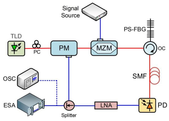
Figure 1.
Schematic diagram of the proposed microwave-signals-generation system based on actively mode-locked OEO. TLD: tunable laser diode, PM: phase modulator, MZM: Mach–Zehnder modulator, EDFA: erbium-doped fiber amplifier, SMF: single-mode fiber, PC: polarization controller, PS-FBG: phase-shifted fiber Bragg grating, PD: photodetector, LNA: low-noise amplifier, ESA: electrical spectrum analyzer, OSC: oscilloscope.
Theoretically, conversion from the phase-modulation to the intensity-modulation is achieved by using an optical notch filter composed of a PS-FBG. In the frequency domain, the signal at the output of the PM contains only the optical carrier and the −1st order sidebands, in which the +1 order optical sideband is filtered out by the notch filter. The output of the PM can be expressed by applying the Bessel function expansion as [14]:
where is the output optical power of the TLD, and are the angular frequency of the optical carrier and the notch angular frequency of the notch filter, respectively. is the modulation index of the phase modulator. is the transmission loss of the OEO loop. is the n-order Bessel function and is an integer.
When the electrical signal with an angular frequency of is applied to the MZM operated at the quadrature point, the output modulated signal of the MZM can be given by applying the Bessel function expansion as [30]:
where m is the modulation index of the MZM. are the n-order Bessel function. is the integer corresponding to the n-order modulation sideband. As shown in Figure 2, a multimode oscillation is excited by cyclic mode-locking each oscillation frequency with the injection signal.

Figure 2.
The principle of mode-locking based on the proposed generation system.
Taking the cascading modulation and the frequency response of the MPF into account, the effective output electrical signal with the angular frequency around can be given by:
where is the responsivity of the PD. There is a fixed frequency differences of and a phase difference of between the adjacent sidemodes. If is equal to the angular frequency interval between the two adjacent modes, the generated pulse trains with frequency spacing of the FSR will be obtained after hundreds cycles in the OEO cavity, resulting in oscillation of all the modes selected by the MPF. Furthermore, if is set to be ( is a positive integer), the multimode with frequency spacing of will oscillate. As a result, the frequency interval of the generated pulse trains can be selected by adjusting the frequency of the injection signal.
Moreover, in the time domain, when the period of the input electrical signal is equal to the of one round-trip time delay of the OEO, only the signal at the time points with net gain can oscillate in the OEO cavity, where the coherent microwave pulse trains can be formed after multiple loop iterations. The pulse repetition interval (PRI) of the generated signals can be expressed as [31]:
where is equal to one round-trip time delay of the OEO, is the positive integer that is equal to 1 for the fundamental mode-locking and more than 1 for the harmonic mode-locking. The pulse width is determined by the bandwidth of the generated signal, and a narrower time-width can be obtained by using the MPF with a larger bandwidth.
3. Results and Discussion
A proof-of-concept experiment was carried out to study the operation of the proposed microwave-signals-generation system based on the actively mode-locked OEO. A TLD (ID Photonics Co Brite DX4) was used to generate the optical carrier with a wavelength of 1549.966 nm and an output power of 15.5 dBm. The optical carrier was then sent to a PM (iXblue MPZ-LN-40) with a bandwidth of 40 GHz. The output of the PM was connected to an MZM (EOSPACE AX-OMVS-40) biased at the quadrature point with a bandwidth of 40 GHz, and a half-wave voltage of 4.5 V. A PS-FBG was used as a notch filter with the notch wavelength of 1549.892 nm. The filtered signal was delayed by transmitting a 100 m SMF. The FSR of the OEO was 1.68 MHz measured by the electrical signal analyzer (Keysight N9040B), indicating that the whole loop delay was ~596.96 ns. The detection of modulated optical sidebands was implemented via a PD (Finisar HPDV2120R) with a typical responsivity of 0.7 A/W and a bandwidth of 50 GHz. Two electrical amplifiers (Keysight N4985A and SHF826H) were employed to provide a gain with a maximum of 50 dB for feeding back the generated electrical signal. A 1:9 electrical coupler was equipped for closing the OEO loop and outputting the generated signal. The electrical injection signal was generated by an electrical signal generator (Keysight E8267D). The electrical spectra and waveforms were measured by an electrical signal analyzer (Keysight N9040B) and a digital storage oscilloscope (Keysight DSO-X 93204A), respectively. The key device parameters in the OEO are listed in Table 1.

Table 1.
Device parameters in the OEO.
To verify the role of mode-locking, the frequency spectrum of the generated microwave signals was measured with a resolution bandwidth (RBW) of 3 kHz. Figure 3a shows the frequency spectrum of the microwave signals generated without external injection, in which case the OEO was operating at the free-running state. The oscillation signals with a dominant mode at 9.25 GHz and multiple spurs were generated. When an RF signal with the frequency of 1.68 MHz and the power of 20 dBm was applied on the MZM, a stable multimode oscillation with bandwidth determined by the passband of the filter was obtained, as is shown in Figure 3b. It indicated that all modes were oscillated simultaneously due to the phase locking [28], while the poor flatness of the frequency comb may be caused by the poor flatness of the PS-FBG notch filter, or the affection of the environmental factors. The inset of the Figure 3b shows that the adjacent mode interval is 1.68 MHz, which is consistent with the FSR of the free-running OEO. The tunability of the central oscillation frequency can be achieved by adjusting the wavelength of the TLD. Figure 3c shows the phase noise curves of the active mode-locked OEO, free-running OEO and the injected RF signal, respectively. The side-mode power was significantly increased compared with that of the free-running OEO, which is similar to the previously reported active mode-locked technique. In addition, comparing with the reported techniques [29], the SSB phase noise was improved by ~10 dB. The phase noise performance of the external injected microwave signal was also measured and given in grey line at Figure 3c. Moreover, Figure 3d shows the transmission and reflection spectrum of PS-FBG used in the experiment, and the notch wavelength was ~1549.892 nm with a reflection bandwidth of ~0.576 nm.
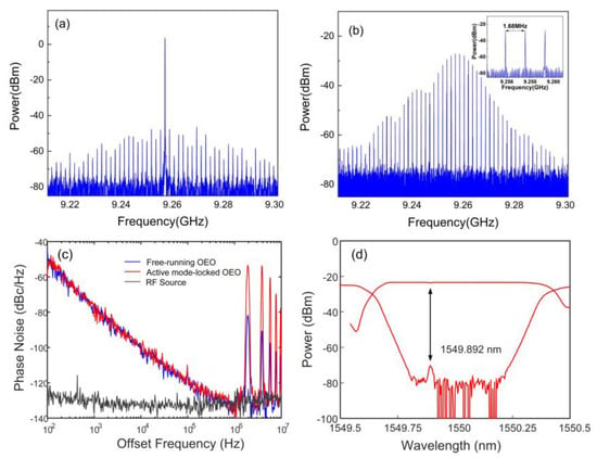
Figure 3.
Measured frequency spectra of the microwave signals generated via the actively mode-locked OEO (a) without external injection and (b) with external injection; (c) phase noise of the inject RF signal and microwave signals generated by free-running OEO and actively mode-locked OEO; (d) reflection and transmission spectra of the PS-FBG.
Figure 4a shows the temporal waveform of the generated microwave pulses based on the fundamental mode-locking, in which the external injection frequency is 1.68 MHz. It is clear to observe that the pulse period of the waveform is about 596.96 ns, which is approximately equal to the fraction of the frequency interval. Figure 4b presents an enlarged view of one pulse with a 3 dB pulse width of 64.38 ns. The inset of Figure 4b shows that the single pulse exhibits an excellent cosine characteristic, and the time period is determined by the central frequency of 9.25 GHz. In order to obtain the velocimetry range of the generated pulses, the velocity ambiguity function is shown in Figure 4c, in which the inset is the waveform of the corresponding four pulses. It indicates that the 3 dB bandwidth of the main lobe is ~0.37 MHz and the frequency interval between lobes is ~1.68 MHz, which corresponds to the anticipated minimum and maximum Doppler frequencies. Based on the Doppler effect, the velocity has been calculated by the velocity measurement equation as follow [32]:
where is the radial velocity of the detected target. is the radar wavelength. is the measurable target Doppler frequency. Thus, the velocity measurement range is calculated to be Mach ~17.6 to ~40.7, which can be in response to the hypersonic aircraft such as HTV-2. Figure 4d shows the ambiguity diagram of the generated four pulses, which exhibits a distinct peg-board distribution. It indicates that the ambiguity diagram of the generated microwave signals corresponds to the waveform of coherent pulse trains.
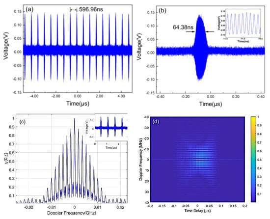
Figure 4.
Generated microwave pulses based on fundamental mode-locking: (a) temporal waveform, (b) enlarged view of the spectrum in (a), (c) velocity ambiguity function, (d) ambiguity diagram.
Figure 5a,b show the generated microwave pulses with a central frequency of 5.47 GHz and 18.91 GHz at fundamental mode-locking state, which is achieved by changing the laser frequencies to 1549.936 nm and 1550.043 nm, respectively. The inset of Figure 5a,b are the corresponding waveforms with the same period of about 596.96 ns. The frequency-tuning range depends on the reflection bandwidth of the PS-FBG, which can be further expanded based on the application of a PS-FBG with larger reflection bandwidth.
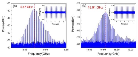
Figure 5.
Frequency spectra of the generated microwave pulses with different center frequency: (a) 5.47 GHz, (b) 18.91 GHz.
As shown in Figure 6, the open-loop frequency response of the proposed active mode-locked OEO is measured by using a vector network analyzer (VNA, Keysight N5244A). The central frequency of the MPF filter is tuned by adjusting the wavelength of the TLD, resulting in the generation of the frequency combs with varied central frequency from 5.47 GHz to 18.91 GHz.
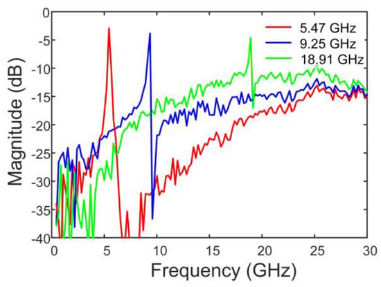
Figure 6.
The open-loop frequency response of the proposed active mode-locked OEO at different central frequencies.
Figure 7 shows the generated microwave pulses with harmonic mode-locking of different orders, which are obtained by varying the frequency of the injection signal. When the injection frequency is changed to 3.36 MHz, 5.04 MHz and 6.72 MHz, the 2nd order, 3rd order and 4th order harmonic mode oscillation are achieved accordingly, and the frequency spectra are shown in Figure 7a,c,e, respectively. The enlarged view in the frequency spectra shows supermodes with a frequency interval of 1.68 MHz among the dominant oscillating modes, and the calculated supermodes suppression ratio is above 25 dB. Figure 7b,d,f sequentially presents the temporal waveforms of the 2nd order, 3rd order, and 4th order harmonic mode-locking, of which the PRI correspond to 297.62 ns, 198.69 ns, and 148.81 ns, respectively. It indicates that the pulse period decreases along with the increasing order of the mode-locking.
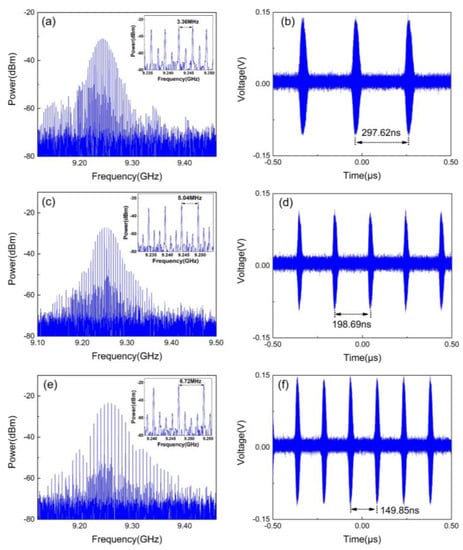
Figure 7.
Generated microwave pulses with harmonic mode-locking: (a,c,e) frequency spectra, (b,d,f) temporal waveforms.
4. Conclusions
In conclusion, we have proposed and demonstrated a novel flexible microwave-pulse generation-scheme based on an actively mode-locked OEO. A microwave pulse signal with central frequency of 9.25 GHz is generated by injecting a low-frequency electrical signal into the OEO. The frequency tunability is achieved by simply adjusting the frequency of the optical carrier, resulting in the central frequency variation of microwave pulses range from 5.47 GHz to 18.91 GHz. Furthermore, the PRI selection is accomplished by the harmonic mode-locking of different orders, and the generated microwave waveforms with varied PRI of 596.96 ns, 297.62 ns, 198.69 ns and 148.81 ns are obtained. The proposed flexible and feasible microwave-pulse-generation method can find applications in the fields of pulse Doppler radar and communications.
Author Contributions
Conceptualization, J.Z. and Y.W.; methodology, J.Z.; software, A.W.; validation, D.Z. (Depei Zhang) and J.Z.; formal analysis, J.Z. and M.Z.; investigation, D.Z. (Daikun Zheng); resources, L.H.; data curation, D.Z. (Depei Zhang); writing—original draft preparation, D.Z. (Depei Zhang); writing—review and editing, J.Z. and D.Z. (Depei Zhang); supervision, X.P.; project administration, X.L.; J.Z. and D.Z. (Depei Zhang) are contributed equally to this work. All authors have read and agreed to the published version of the manuscript.
Funding
This work was supported by Hubei Provincial Natural Science Foundation of China (ZRMS2022002625, ZRMS2022002317) and National Key Research and Development Program of China (2018YFB2201902).
Data Availability Statement
Data underlying the results presented in this paper are not publicly available at this time but may be obtained from the authors upon reasonable request.
Conflicts of Interest
The authors declare no conflict of interest.
References
- Capmany, J.; Novak, D. Microwave photonics combines two worlds. Nat. Photon. 2007, 1, 319–330. [Google Scholar] [CrossRef]
- Yao, J. Microwave photonics. J. Lightwave Technol. 2009, 27, 314–335. [Google Scholar] [CrossRef]
- Prasad, R. Overview of wireless personal communications: Microwave perspectives. IEEE Commun. Mag. 1997, 35, 104–108. [Google Scholar] [CrossRef]
- Peng, Z.Y.; Li, C.Z. Portable Microwave Radar Systems for Short-Range Localization and Life Tracking: A Review. Sensors 2019, 19, 1136. [Google Scholar] [CrossRef] [PubMed]
- Cibiel, G.; Regis, M.; Llopis, O.; Rennane, A.; Bary, L.; Plana, R.; Kersale, Y.; Giordano, V. Optimization of an Ultra Low Phase Noise Sapphire-SiGe HBT Oscillator Using Nonlinear CAD. IEEE Trans. Ultrason. Eng. 2004, 51, 33–40. [Google Scholar]
- Gravel, J.F.; Wight, J.S. On the Conception and Analysis of a 12-GHz Push-Push Phase-Locked DRO. IEEE Trans. Microwave Theory Tech. 2006, 54, 153–159. [Google Scholar] [CrossRef]
- Madani, M.H.; Abdipour, A.; Mohammadi, A. Analysis of performance degradation due to non-linearity and phase noise in orthogonal frequency division multiplexing systems. IET Commun. 2010, 4, 1226–1237. [Google Scholar] [CrossRef]
- Porzi, C.; Falconi, F.; Sorel, M.; Ghelfi, P.; Bogoni, A. Flexible millimeter-wave carrier generation up to the Sub-THz with silicon photonics filters. J. Lightwave Technol. 2021, 39, 7689–7697. [Google Scholar] [CrossRef]
- Singh, M.; Raghuwanshi, S.K. Effect of higher order dispersion parameters on optical millimeter-wave generation using three parallel external optical modulators. J. Appl. Phys. 2015, 117, 023116. [Google Scholar] [CrossRef]
- Yao, X.S.; Maleki, L. Optoelectronic microwave oscillator. J. Opt. Soc. Amer. B 1996, 13, 1725–1735. [Google Scholar] [CrossRef]
- Bouchier, A.; Saleh, K.; Merrer, P.H.; Llopis, O.; Cibiel, G. Theoretical and experimental study of the phase noise of opto-electronic oscillators based on high quality factor optical resonators. In Proceedings of the 2010 IEEE International Frequency Control Symposium, Newport Beach, CA, USA, 1–4 June 2010; pp. 544–548. [Google Scholar]
- Eliyahu, D.; Seidel, D.; Maleki, L. Phase Noise of a High Performance OEO and an Ultra Low Noise Floor Cross-Correlation Microwave Photonic Homodyne System. In Proceedings of the 2008 IEEE International Frequency Control Symposium, Honolulu, HI, USA, 19–21 May 2008; pp. 811–814. [Google Scholar]
- Saleh, K.; Henriet, R.; Diallo, S.; Lin, G.; Martinenghi, P.; Balakireva, I.V.; Chembo, Y.K. Phase noise performance comparison between optoelectronic oscillators based on optical delay lines and whispering gallery mode resonators. Opt. Express 2014, 22, 32158–32173. [Google Scholar] [CrossRef] [PubMed]
- Li, W.; Yao, J. A wideband frequency tunable optoelectronic oscillator incorporating a tunable microwave photonic filter based on phase-modulation to intensity-modulation conversion using a phase-shifted fiber bragg grating. IEEE Trans. Microwave Theory Tech. 2012, 60, 1735–1742. [Google Scholar] [CrossRef]
- Jiang, Y.; Yu, J.-L.; Wang, Y.-T.; Zhang, L.-T.; Yang, E.-Z. An optical domain combined dual-loop optoelectronic oscillator. IEEE Photonics Technol. Lett. 2007, 19, 807–809. [Google Scholar]
- Zhou, W.; Blasche, G. Injection-locked dual opto-electronic oscillator with ultra-low phase noise and ultra-low spurious level. IEEE Trans. Microwave Theory Tech. 2005, 53, 929–933. [Google Scholar] [CrossRef]
- Banerjee, A.; de Britto, L.A.D.; Pacheco, G.M. Analysis of injection locking and pulling in single-loop optoelectronic oscillator. IEEE Trans. Microw. Theory Tech. 2019, 67, 2087–2094. [Google Scholar] [CrossRef]
- Xu, X.; Dai, J.; Dai, Y.; Yin, F.; Zhou, Y.; Li, J.; Yin, J.; Wang, Q.; Xu, K. Broadband and wide-range feedback tuning scheme for phase-locked loop stabilization of tunable optoelectronic oscillators. Opt. Lett. 2015, 40, 5858–5861. [Google Scholar] [CrossRef] [PubMed]
- Zhang, Y.; Hou, D.; Zhao, J. Long-term frequency stabilization of an optoelectronic oscillator using phase-locked loop. J. Lightwave Technol. 2014, 32, 2408–2414. [Google Scholar] [CrossRef]
- A Saleh, K.; Lin, G.; Chembo, Y.K. Effect of Laser Coupling and Active Stabilization on the Phase Noise Performance of Optoelectronic Microwave Oscillators Based on Whispering-Gallery-Mode Resonators. IEEE Photon. J. 2014, 7, 5500111. [Google Scholar] [CrossRef]
- Brunetti, G.; Armenise, M.N.; Ciminelli, C. Chip-Scaled Ka-Band Photonic Linearly Chirped Microwave Waveform Generator. Front. Phys. 2022, 10, 785650. [Google Scholar] [CrossRef]
- Hao, T.; Cen, Q.; Dai, Y.; Tang, J.; Li, W.; Yao, J.; Zhu, N.; Li, M. Breaking the limitation of mode building time in an optoelectronic oscillator. Nat. Commun. 2018, 9, 1839. [Google Scholar] [CrossRef]
- Wang, Y.; Li, X.; Zhang, J.; Wo, J. Spurious level and phase noise improved fourier domain mode-locked optoelectronic oscillator based on a self-injection-locking technique. Opt. Express 2021, 29, 7535–7543. [Google Scholar] [CrossRef]
- Zeng, Z.; Zhang, L.; Zhang, Y.; Tian, H.; Liu, Y. Microwave pulse generation via employing an electric signal modulator to achieve time-domain mode locking in an optoelectronic oscillator. Opt. Lett. 2021, 46, 2107–2110. [Google Scholar] [CrossRef]
- Wu, Y.; Zeng, Z.; Zhang, L.; Zhang, Z.; Liu, Y. Modeling an actively mode-locked optoelectronic oscillator based on electric amplitude modulation. Opt. Express 2021, 29, 23835–23846. [Google Scholar] [CrossRef]
- Zhao, H.; Cao, Z.; Yang, S.; Zhai, Y.; Ou, J.; Chi, H. Active mode-locking optoelectronic oscillator. Opt. Express 2020, 28, 33220–33227. [Google Scholar]
- Wo, J.; Zhang, J.; Wang, Y. Actively mode-locked optoelectronic oscillator for microwave pulse generation. Opt. Laser Technol. 2022, 146, 107563. [Google Scholar] [CrossRef]
- Zeng, Z.; Zhang, Z.; Zhang, L.; Wu, Y.; Zhang, S.; Li, H.; Liu, Y. Harmonically mode-locked optoelectronic oscillator with ultra-low supermode noise. Opt. Laser Technol. 2022, 151, 413–416. [Google Scholar] [CrossRef]
- Li, Y.; Wang, M.; Zhang, J.; Mu, H.; Wang, C.; Yan, F. Supermode noise suppression with polarization-multiplexed dual-loop for active mode-locking optoelectronic oscillator. Opt. Lett. 2022, 47, 413–416. [Google Scholar] [CrossRef] [PubMed]
- Jahanbakht, S. Frequency domain analysis of optoelectronic oscillators utilizing optical and RF resonators with arbitrary transfer functions. J. Opt. Soc. Am. B 2021, 38, 2813–2822. [Google Scholar] [CrossRef]
- Zhen, Z.; Zhang, L.; Wu, Y.; Zhang, Z.; Zhang, S.; Zhang, Y.; Sun, B.; Liu, Y. Multi-format microwave signal generation based on an optoelectronic oscillator. Opt. Express 2021, 29, 30834. [Google Scholar]
- Mahafza, B.R. Radar systems analysis and design using MATLAB. Sci. Rep. 2000, 21, 18–19. [Google Scholar]
Publisher’s Note: MDPI stays neutral with regard to jurisdictional claims in published maps and institutional affiliations. |
© 2022 by the authors. Licensee MDPI, Basel, Switzerland. This article is an open access article distributed under the terms and conditions of the Creative Commons Attribution (CC BY) license (https://creativecommons.org/licenses/by/4.0/).