1. Introduction
As a non-separable quadratic phase existing in a partially coherent light field, the twist phase has aroused extensive interest since the first discovery of Simon and Mukunda in 1993 [
1] because of its novel properties and potential applications [
2,
3]. Recently, a new type of twisting phase has been proposed [
4,
5,
6], and it can be experimentally generated by a spatial light modulator (SLM) [
7]. The new twisted beam that is modulated by the twisting phase (cross-phase) can act on completely coherent beams, and it has an arbitrarily controllable rotation angle during propagation [
7]. Meanwhile, some potential applications of the new twisted beams have been found in micro-particle manipulation [
8] and the measurement of a vortex optical field [
9,
10]. Nevertheless, most research about twisted beams is focused on the scalar optical field with uniform polarization in the field cross-section. Recently, the advances of vector beams with spatially variant states of polarization (SoP) have triggered some novel physical ideas and applications, e.g., 3D focal field manipulation [
11,
12], optical data storage [
13], super-resolution imaging [
14,
15], optical information transmission [
16], and second harmonic generation [
17,
18]. In particular, the modulation of the spatial phase on the vector beam has generated many interesting physical phenomena and applications, such as azimuthal modulation (vortex) [
19,
20,
21], radial modulation, and the caustic phase modulation [
22,
23,
24,
25]. These modulations play an important role in the application, especially for the efficient manipulation of SoP during propagation. As a novel phase, the optical field can be rotated during propagation due to the existence of the twisting phase, and the velocity of rotation is dependent on the twist intensity coefficient [
6]. The effect of twisting phases on a vector beam may lead to interesting phenomena and potential applications. In particular, the conventional method for the measurement of the vortex topological charge number is taking advantage of the interference of the vortex with a plane light wave. Recently, the detection of the two vortex phases in the vector vortex beams for the first time with a simple radial grating has been demonstrated [
26]. The measurement of the topological charge number of a scalar vortex through a twisting phase has been observed [
10,
27], and the simultaneous measurement of two vortex topological charges in a twisted vector beam by twisting phases is anticipated.
In this work, the twisted vector beams with the modulation of the twisting phases and spatially variant SoP are experimentally generated and observed. The propagation dynamics and the evolution of the SoP of the twisted vector vortex optical field are analyzed in detail. The effect of twisting phases on the polarization dynamics of the vector optical field is systematically examined. The presence of twisting phases results in compression and stretching of the orthogonal polarization components and the linear-circular polarization conversions during propagation. The SoP and the optical field of the anisotropic twisted optical field are rotated by the twisting phase. The rotating angles and velocities are sensitively dependent on the twisting coefficients. Furthermore, the two vortex topological charges embedded in the orthogonal polarization components can be simultaneously measured through the twisting phases in a twisted vector vortex beam.
2. Experimental Generation of a Twisted Vector Optical Field
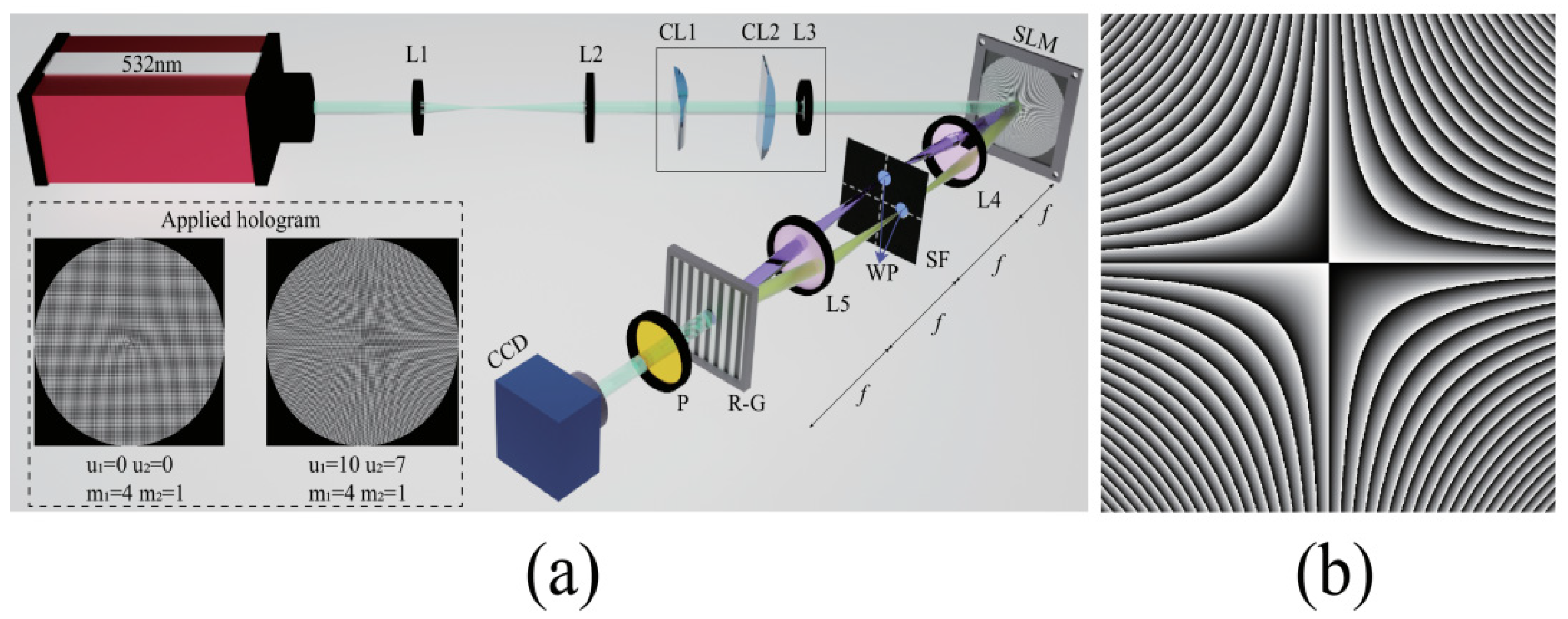
The experimental setup for the generation of a twisted vector optical field is shown in
Figure 1a, and the spatial distribution of twisted phase
uxy with
u = 10 mm
−2 is shown in
Figure 1b. After the beam expansion and collimation (by the lenses L1 and L2), the cylindrical lenses CL1 and CL2 are employed to generate an anisotropic beam (i.e., the beam width along the
x- and
y-directions are not equal). The linearly polarized laser beam with a wavelength of 532 nm is incident on the reflective spatial light modulator (SLM, LETO, 1920 × 1080 pixels, each pixel has a 6.4 μm × 6.4 μm size). The transmittance function of the computed holographic grating (CHG) which is loaded in the SLM is T (
x0,
y0) = 0.5 +
γ [cos(2π
f0x0 +
δ1) + cos(2π
f0y0 +
δ2)]/4, where
γ is the modulation depth, and
f0 is the spatial frequency of CHG. The
δ1 and
δ2 are the additional phase distributions for the vertical and horizontal CHGs, respectively. The +1-order diffractions of the holographic grating in the
x- and
y-directions are selected by the spatial filter (SF), followed by converting into left- and right-circular polarizations (or orthogonally linear polarizations) by the λ/4 (or λ/2) wave plate (WP). The two +1-order diffraction beam spots are recombined by the Ronchi grating (RG) in the rear focal plane of L5 to generate the desired vector light field. It should also be pointed out that the spatial frequency of the CHG needs to match the period of the RG.
In this work, the phase distributions in the CHG are set as
δ1 =
u1xy +
m1θ,
δ2 =
u2xy +
m2θ, where
uj (
j = 1 or 2) is the twist intensity coefficients (TIC),
mj is the topological charge numbers of a vortex, and
θ = argtan(
y/
x), respectively. The generated twisted vector vortex optical field can be expressed as:
where
σx and
σy represent the beam width of the generated beam along the
x- and
y-directions, respectively.
e1 = (
ex + exp(
iΔ
θ)
ey),
e2 = (
ex − exp(
iΔ
θ)
ey).
ex and
ey are the unit vectors in the
x- and
y-directions, respectively. Here, the value of Δ
θ (0 or π/2) in Equation (1) is determined by the different wave plates in the experiment. When the half-wave plates are used in the experiment, Δ
θ = 0, and there are hybrid SoPs including linear, circular, and elliptical polarizations located at different positions of the field cross-section. On the other hand, Δ
θ = π/2 if a pair of quarter-wave plates is used and there are locally linear polarizations with different polarization directions located at different positions in the field cross-section. The hybrid SoP distribution (Δ
θ = 0) can be regarded as the superposition of two orthogonally linear polarization components (azimuthal angles are 45° and 135°), whereas the locally linear polarization distribution (Δ
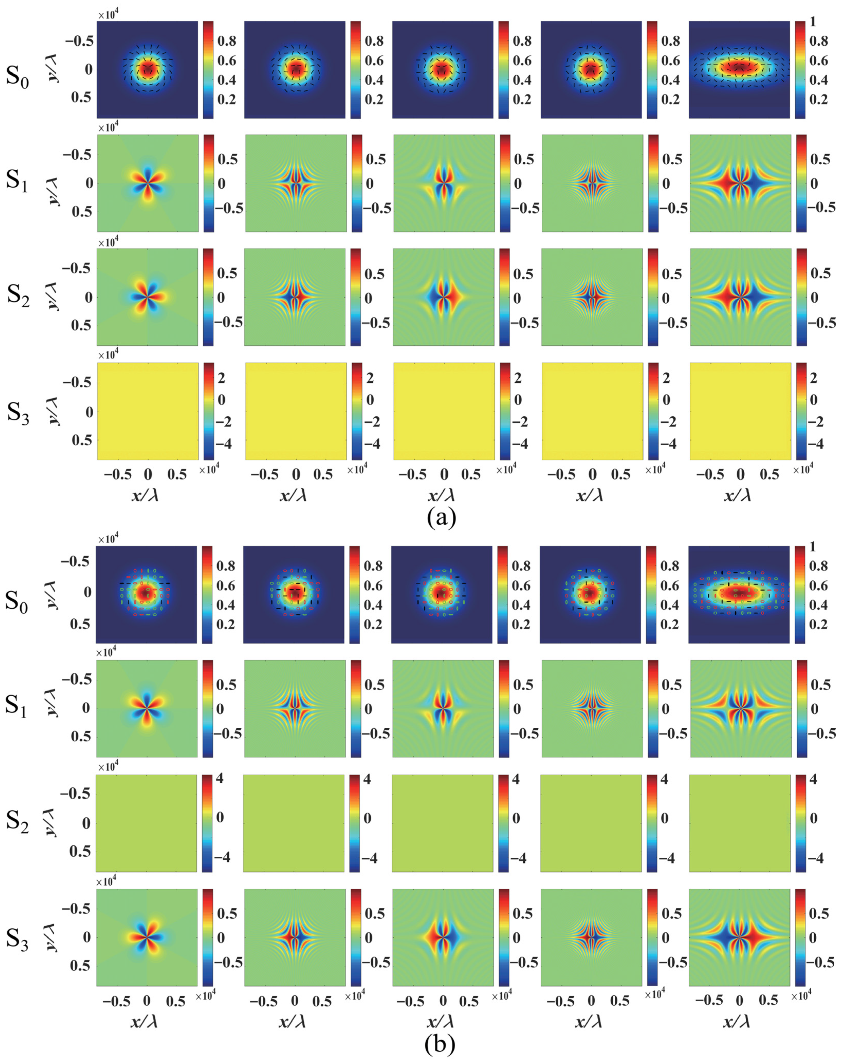
θ = π/2) is the superposition of two orthogonally circular polarization components. The initial states of polarization (SoP) of the twisted vector beams with locally linear polarization (Δ
θ = π/2) and hybrid polarizations (Δ
θ = 0) are shown in
Figure 2a,b by the Stokes parameters S
0, S
1, S
2, and S
3, respectively. Comparing the difference in SoP between the locally linear polarization (see
Figure 2a) and hybrid polarizations (see
Figure 2b), their S
2 and S
3 are reciprocal interchange, as analyzed above. To analyze the effect of the twisting phase on the SoP distribution, we rewrite the light field of Equation (1) as
The initial SoP distributions of the optical field are modulated by the twisting phases
u1xy and
u2xy. An important parameter is the angle of polarization ellipse, describing the SoP distribution in position (
x,
y). It can be obtained from Equation (2) as
The angle of polarization ellipse α(
x,
y) increases with increasing values (
u1 −
u2)
xy/2, with a certain vortex topological charge
mj, as recognized from Equation (3). The effect of different TICs (
u1 and
u2) on the intensity pattern and the SoP distribution of vector light fields is shown in
Figure 2. For the case with a locally linear polarization (Δ
θ = π/2),
u2 = 0 and
u1 take different values, e.g.,
u1 = 0 mm
−2 and
u1 = 10 mm
−2, and the angle of polarization α(
x,
y) increases with the increasing values of
u1xy/2. The polarization direction of the linear polarization rotates clockwise with increasing
u1 in the first and third quadrants, whereas in the second and fourth quadrants, the polarization direction rotates counterclockwise with increasing
u1, as shown in
Figure 2a. It is because the signs of
x and
y are the same in the first and third quadrants; thus, the angle of polarization α(
x,
y) increases with the increasing values of
u1. On the other hand, the signs of
x and
y are opposite in the second and fourth quadrants, and the angle of polarization α(
x,
y) decreases with the increasing values of
u1. When
u1 and
u2 vary simultaneously, the angle of polarization α(
x,
y) depends on the values (
u1 −
u2)
xy/2. Furthermore, the variation in polarization distributions results in the novel shapes of the
x and
y polarization components. The intensity pattern of the
x- and
y-components are closely related to the values of
u1 and
u2, as shown in the Stokes parameter diagram in
Figure 2. In addition, the effect of the TIC on the SoP in the field cross-section of the anisotropic beams with σ
x ≠ σ
y is similar to that of the isotropic beam σ
x = σ
y, but the intensity distribution is an elliptical shape for the anisotropic beams instead of a circular shape of the isotropic beam, as shown in
Figure 2. Moreover, the underlying physics of the effect of twisting phases on the angle of polarization ellipse α(
x,
y) of the beam with hybrid polarizations (Δ
θ = 0) are the same as those of locally linear polarization (Δ
θ = π/2). However, compared to locally linear polarization, there is an additional phase difference π/2 between the
x- and
y-components for the hybrid polarization distribution, as shown in
Figure 2b.
3. SoP Evolution and Propagation Dynamics of a Twisted Vector Beam
The twisted vector vortex beams that propagate along the
z-axis in free space can be calculated by the Rayleigh–Sommerfeld diffraction integral formula [
28]:
Here the
z-component is neglected under the paraxial condition. One of the novel properties of a scalar twisted light field is that the optical field initially compresses and then stretches during propagation. In addition, the beam can rotate about the propagation axis for the anisotropic case σ
x ≠ σ
y [
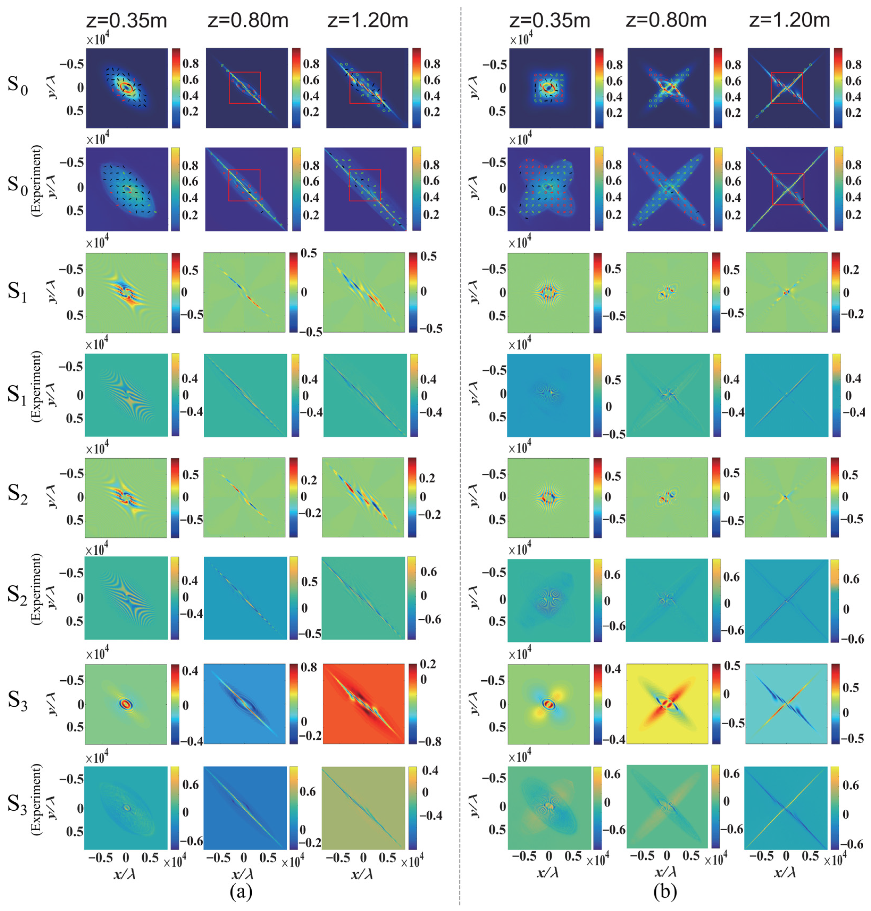
6]. Since the twisted vector beams can be regarded as the superposition of two twisted vortices with orthogonal polarizations, the presence of twisting phases in the propagation of a vector beam with orthogonal polarizations may lead to the SoP redistribution, linear-circular polarization conversions, and the polarization rotation during propagation. The evolution of the SoP and the optical field of the twisted vector beams with different modulation parameters (TICs and vortex topological charges) in different propagation distances are shown in
Figure 3. When the values of the TICs of the twisted vector beams take the same sign (i.e., positive or negative), the polarization components compress in the same direction with different speeds due to the different values of the TICs, as shown in
Figure 3a. For the case of
u1 = 10 mm
−2,
u2 = 15 mm
−2,
m1 = 4,
m2 = −1, the right circularly polarization component completely compresses to a threadiness distribution along the azimuthal angle 135° at
z = 0.8 m, whereas the left circularly polarization component uncompresses and distributes in the field cross-section. On the other hand, the left circular polarization component completely compresses to a threadiness distribution along the azimuthal angle 135° at
z = 1.2 m, but the right-circular polarization component is uncompressed and distributed in the field cross-section. Meanwhile, the linear-circular polarization conversions are observed in the field cross-section during the different polarization components evolving with different modulation parameters. When the sign of
u1 is opposite to that of
u2, the two orthogonal polarization components of the vector optical field initially compress and then stretch along the orthogonal directions, e.g., 45° and 135° in the case of
u1 = 10 mm
−2,
u2 = −10 mm
−2,
m1 = 4,
m2 = −1, as shown in
Figure 3b. The left- and right-circular polarization components simultaneously compress to a pair of orthogonal threadiness distributions at the propagation distance of
z = 1.2 m. The underlying physics for the evolutions of the twisted vector beams with different signs of
u1 and
u2 are similar to the case with the same sign of
u1 and
u2, but the compression and stretching occur along the orthogonal directions of azimuthal angles 45° and 135°. The coherent superposition of the two orthogonal polarization components during propagation leads to the novel linear-circular polarization conversions and evolutions of SoP, as shown in
Figure 3.
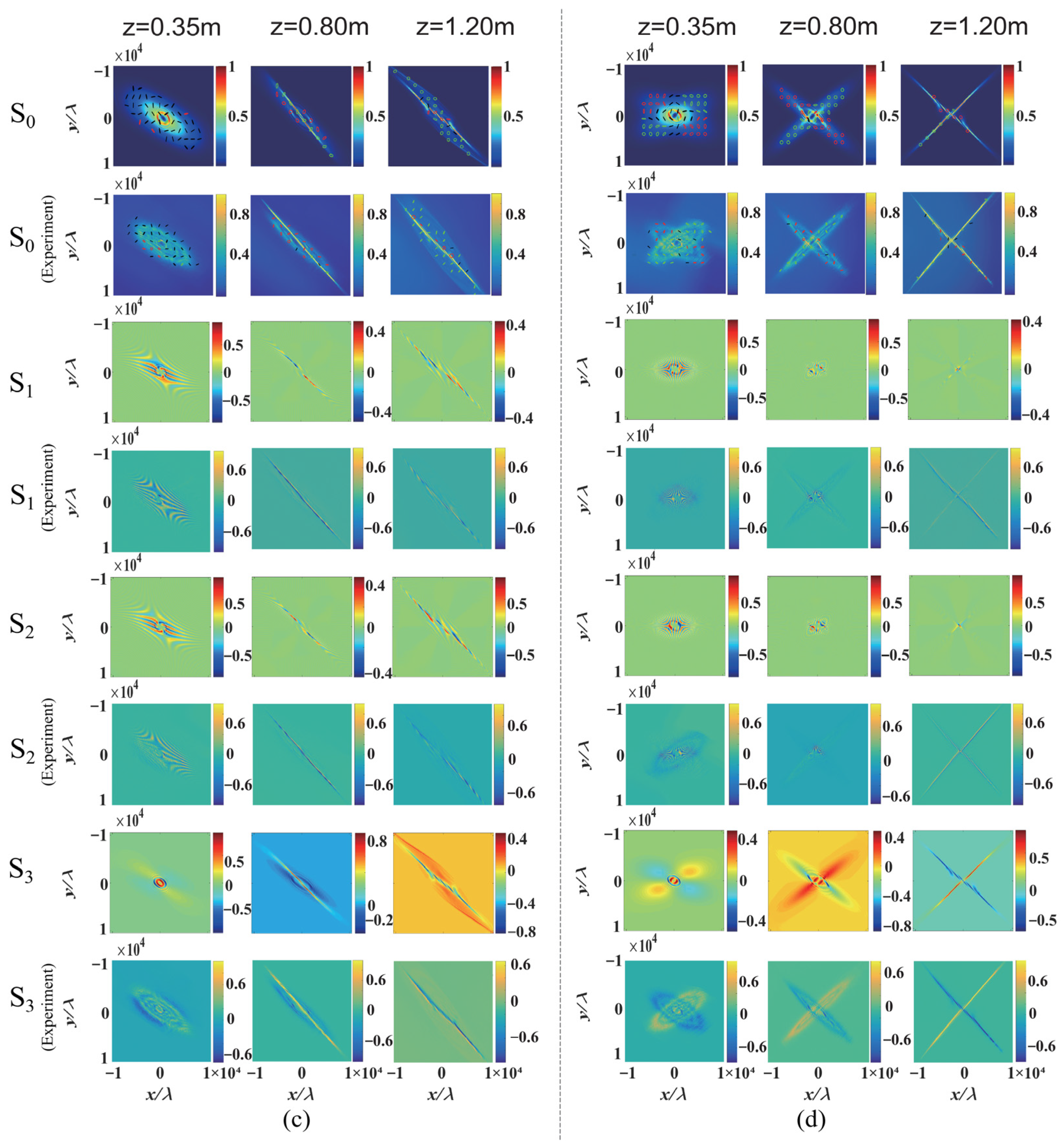
In addition, the anisotropic twisted optical field σ
x ≠ σ
y rotates about the propagation direction due to the existence of the twisting phase during propagation, and the rotation and evolution of the optical field are strongly dependent on the TIC [
6]. Another interesting feature is that there are two twisting phases embedded in the two orthogonal polarization components for the twisted vector beams. When the TICs of the vector beams take the same sign (positive or negative), the two orthogonal polarization components rotate in a similar direction. For the case of
u1 = 10 mm
−2 and
u2 = 15 mm
−2 (see
Figure 3c), the two orthogonal polarization components rotate clockwise during propagation, but the rotation behaviors are different due to the different TICs. When the sign of
u1 is opposite to that of
u2, the two orthogonal polarization components of the vector optical field rotate in opposite directions. The left circular polarization component rotates clockwise, whereas the right polarization component rotates anti-clockwise for
u1 = 10 mm
−2 and
u2 = −10 mm
−2, as shown in
Figure 3d.
The appearance of twisting phases in the propagation of a vector beam with the hybrid SoP distribution (Δ
θ = 0) also induces the conversion of linear-circular polarization and the rotation of SoP and optical field, similar to that of locally linear polarizations (Δ
θ = π/2). The underlying physics for the propagation dynamics of a vector beam with the hybrid SoP distribution are similar to those of the twisted vector beams with locally linear polarization (Δ
θ = π/2). However, there is an additional phase difference π/2 between the
x- and
y-polarization components for the hybrid SoP distribution compared to that with locally linear polarization, as shown in
Figure 3 and
Figure 4.
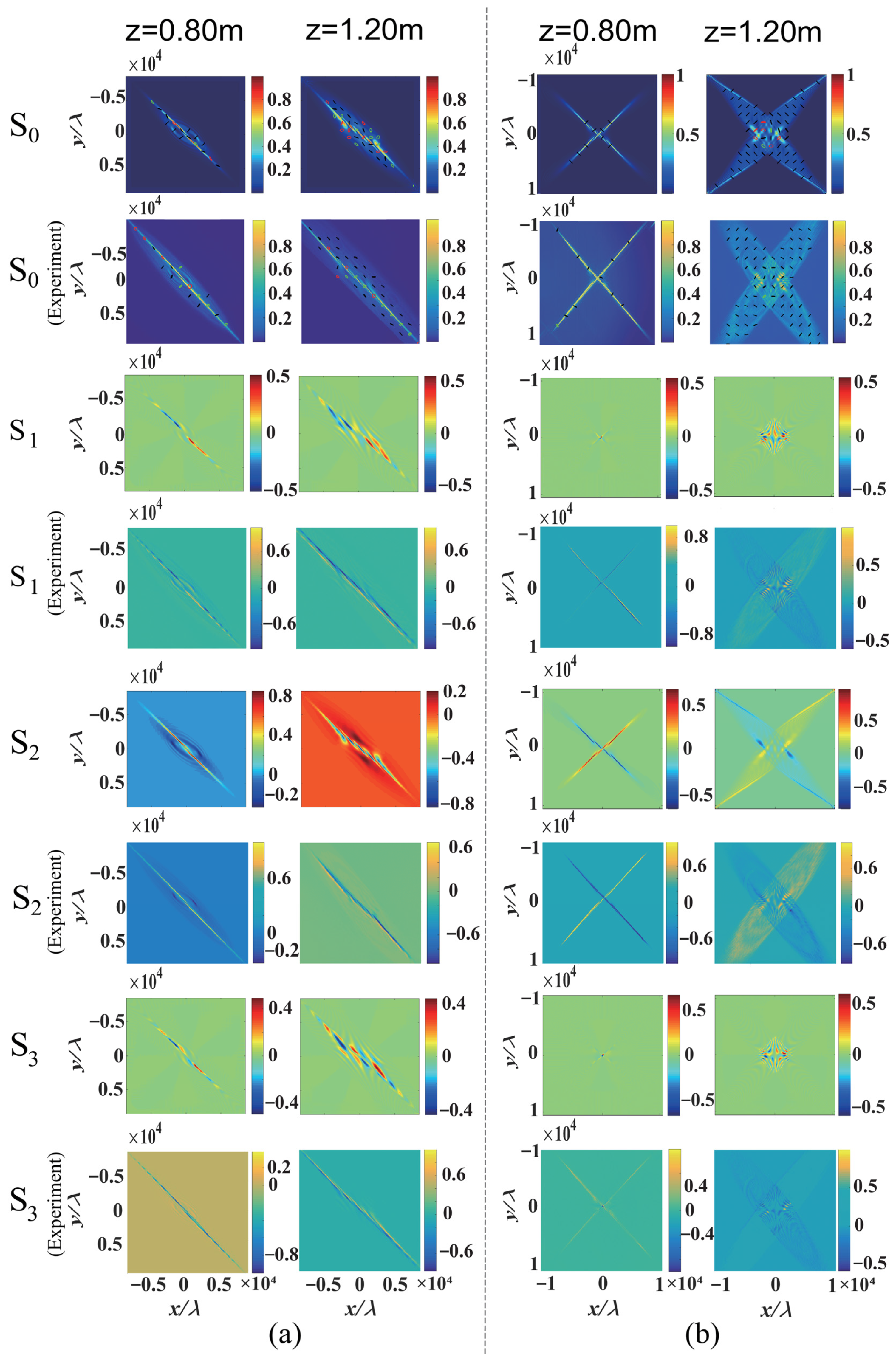
Obviously, the evolution of SoP distribution during propagation is sensitively related to the twisting phase modulation. The Stokes parameters S
1 (the linear polarization components in the horizontal or vertical direction), S
2 (the linear polarization components of 45° and 135°), and S
3 (the left and right circular polarization components) perform the processes of compression and stretching and rotation (for the anisotropic twisted optical field σ
x ≠ σ
y) during propagation, as shown in
Figure 3,
Figure 4 and
Figure 5. However, the propagation distances for the compression and stretching of different polarization components (S
1, S
2, and S
3) are different due to the different initial phases of polarization components. The underlying physics are further discussed in
Section 5.
4. Simultaneous Measurement of Two Vortex Topological Charges in a Twisted Vector Beam by Twisting Phases
Another interesting phenomenon about the twisting phase is the number of vortex topological charges that can be measured through a twisting phase [
10,
27]. As recognized from Equation (1), the topological charges
m1 and
m2, embedded in the two orthogonal polarization components
e1 and
e2, can be measured simultaneously due to the existence of the twisting phases
u1xy and
u2xy. Here, we demonstrate that the two vortex topological charges can be simultaneously measured based on different TICs,
u1 and
u2, by analyzing the intensity patterns of the twisted vector optical field. When the intensity patterns are compressed into threadiness distributions, the bright and dark interference fringes appear at the center of the light field. The number of interference dark fringes is equal to the number of vortex topological charges, and the sign of the vortex topological charges can be identified by observing the direction of the dark fringes. When the sign of TIC is opposite to that of the vortex topological charge (one is positive but the other is negative), the directions of the dark stripes are almost horizontal. For the case of the vortex topological charge
m2 = −1 and
u2 = 15 mm
−2, a horizontal dark stripe appears at the propagation distance
z = 0.8 m, as shown in
Figure 3a. On the other hand, the directions of the stripes are almost vertical when the signals of TIC and the vortex topological charge are similar (both are positive or negative), e.g., there are four vertical dark stripes at the propagation distance
z = 1.2 m for
m1 = 4 and
u1 = 10 mm
−2, as shown in
Figure 3a. If the signs of TIC are opposite, e.g., one is positive and the other is negative, the stripes with the orthogonal polarizations compress in the orthogonal directions, as shown in
Figure 3b. In the case of
u1 = −
u2, the values and signs of two vortex topological charges can be simultaneously observed at a certain propagation distance, e.g., for the case
u1 = −
u2 = 15 mm
−2,
m1 = 4,
m2 = −1 at
z = 1.2 m (see
Figure 3b). In addition, for the anisotropic intensity distribution
σx ≠
σy, the twisted beam rotates about the propagation direction during propagation. However, the different polarization components are always compressed along the azimuthal angles of 45° or 135°, and the compressed stripes appear at different propagation distances due to the difference in twisting phases during propagation, as shown in
Figure 3c,d and
Figure 4b.
For the cases of the twisted vector beams with the locally linear polarization or the hybrid SoP, the two vortex topological charges can be simultaneously measured with different TICs,
u1 and
u2, by observing the intensity patterns (S
0 distributions) of the twisted vector optical field.
Figure 5 describes the zoom of the central parts of the corresponding interference fringes in
Figure 3 and
Figure 4, as highlighted by the red dotted lines in
Figure 4. From
Figure 5, the experimental results further provide evidence to confirm the theoretical predictions for the simultaneous measurement of two vortex topological charges in a twisted vector beam. In addition, it is important to note that the hybrid SoP distribution (Δ
θ = 0) can be regarded as the superposition of two orthogonally linear polarization components (azimuthal angles are 45° and 135°), whereas the locally linear polarization distribution (Δ
θ = π/2) is the superposition of two orthogonally circular polarization components. Therefore, the two vortex topological charges of the vector beam with the locally linear polarizations (Δθ = π/2) are also measured by the bright and dark interference fringes in the patterns of S
3 (the left- and right-circularly polarized components), as shown in
Figure 5a,b. Similarly, the two vortex topological charges for the vector beam with hybrid polarizations (Δ
θ = 0) can also be measured by looking at the fringes in the patterns of S
2 (the 45° and 135° linearly polarized components), as shown in
Figure 5c,d.
5. Discussion
The manipulation of a structured optical and its applications in the corresponding field have been an emerging topic in modern optics, ranging from optical forces on particles to quantum information processing [
29]. The Poynting vector [
30] and azimuthal energy flow [
31] of a vortex have been demonstrated for the rotation of the optical field. In this work, the effect of twisting phases
uxy on a vector optical field results in the symmetry break of the vortex phase and the change in the azimuth energy flow, leading to the redistribution of the state of polarization. Since the vector optical can be regarded as the coherent superposition of two vortices with orthogonal polarizations and different twisting phases modulations (see Equation (1), therefore, the evolution of the state of polarization at different distances can also be explained according to the coherent superposition of the two orthogonal polarization components due to the modulation of the twisting phases. For the case of locally linear polarizations (Δ
θ = π/2 in Equation (2)), the initial optical field can be treated as the superposition of two orthogonally linear polarization components with the same phase but different amplitude distributions (see Equation (2)). On the other hand, for the hybrid polarizations (Δ
θ = 0), the initial optical field can be considered as the superposition of two orthogonally linear polarization components with the phase difference π/2 and different amplitude distributions (see Equation (2)). Since the two orthogonal polarization components are modulated with different twisting phases (see Equations (1) and (2)), the two orthogonal polarization components perform the processes of compression and stretching and rotation (for the anisotropic twisted optical field σ
x ≠ σ
y) during propagation. The coherent superposition of the orthogonal polarization components leads to the redistribution of the SoP and the linear-circular polarization conversions during propagation, as shown in
Figure 3 and
Figure 4 for the distributions of the Stokes parameters S
1, S
2, S
3.
As an important application of the structured optical field, the optical manipulation of a micro-particle with a structured vector beam has been widely exploited. Recently, a light-driven opto-thermocapillary nanomotor on solid substrates has been developed [
32]. In this work, the existence of a twisting phase breaks the symmetry of the vortex phase and changes the azimuth energy flow in a vector optical field. It will inevitably lead to more complex polarization and angular momentum evolution during the propagation of the twisted vector light field. Moreover, the evolutions of polarization and angular momentum are sensitively dependent on the twisting phase. Therefore, the twisted vector beam may provide a new way for the potential applications for optical trapping and optical rotors.

 ,
, 


