Communication

Laguerre-Gaussian Beams with an Increased Dark Area and Autofocusing

by
Victor V. Kotlyar
1,2,
Eugeny G. Abramochkin
3,
Alexey A. Kovalev
1,2,* and
Alexandra A. Savelyeva
1,2
1
Image Processing Systems Institute of the RAS—Branch of FSRC “Crystallography & Photonics” of the RAS, 151 Molodogvardeyskaya St., 443001 Samara, Russia
2
Samara National Research University, 34 Moskovskoe Shosse, 443086 Samara, Russia
3
Lebedev Physical Institute, 221 Novo-Sadovaya St., 443011 Samara, Russia
*
Author to whom correspondence should be addressed.
Photonics 2022, 9(10), 708; https://doi.org/10.3390/photonics9100708
Submission received: 30 August 2022 / Revised: 23 September 2022 / Accepted: 25 September 2022 / Published: 28 September 2022

Abstract

:
We introduce and investigate a novel Laguerre-Gaussian (LG) beam, different from the conventional modal LG beams, which conserve the transverse intensity structure (up to scale) on propagation. The proposed beam does not conserve its structure on free space propagation but possesses some interesting properties. This beam is Fourier-invariant, and it has an increased dark area both in the initial (waist) plane and in the far field. Thus, without changing the topological charge of the beam, varying the radial (lower) index of the associated Laguerre polynomial allows increasing or decreasing the effective diameter of the central dark spot in the intensity pattern. In addition, the beam is autofocusing, i.e., the intensity distribution at the Rayleigh distance from the waist has a shape of the light ring (at any value of the radial index) with the minimal diameter and with the maximal on-ring intensity. Such a beam can be adopted for microparticle manipulation. Increasing the dark area in the focus of a high-aperture spherical lens allows the simultaneous trapping of several absorbing microparticles into this dark area.

1. Introduction

For many years, vortex Laguerre-Gaussian (LG) beams have attracted a a great deal of interest due to their wide practical applications in optical trapping [1], wireless telecommunications [2], atmosphere probing [3], quantum informatics [4], atom cooling [5], optical microscopy of single molecules [6] and quantum dots [7]. Besides, the LG beams have been very thoroughly studied theoretically. For instance, the possibility of the orbital angular momentum (OAM) of light was at first shown right for the LG beams [8]. There are known many modifications of the LG beams, such as elegant LG beams [9], Hermite-Laguerre-Gaussian beams [10], asymmetric LG beams [11], and products of LG beams [12]. The LG beams can be generated by lasers [13,14,15,16], mode converters [17], and using a spatial light modulator [18]. However, despite the long history of the LG beams, their potential is still not exhausted.
In this work, we investigate a novel LG beam with its topological charge being equal to the difference between the azimuthal (upper) and radial (lower) indices of the associated Laguerre polynomial. In contrast, the radial polar coordinate is raised to a power equal to the sum of these indices. Thus, in contrast to the conventional LG beams, the topological charge of the studied beam is not equal to the power of the radial coordinate. On the one hand, it violates the modal propagation (shape invariance) of such a beam in free space. On the other hand, the beam discussed demonstrates interesting properties: autofocusing and the ability to control the diameter of the central dark intensity spot without changing the topological charge of the beam.

2. Fourier-Invariant Laguerre-Gaussian Beams with an Increased Dark Area

Here, we consider a coherent paraxial monochromatic light field with the following complex amplitude in the initial plane (z = 0):
E n , m ( r , φ ) = exp ( r 2 w 2 + i ( m n ) φ ) ( r w ) m + n L n m ( r 2 w 2 ) ,
where (r, φ) are the polar coordinates, w is the waist radius of the Gaussian beam, L n m ( x ) is the associated Laguerre polynomial. Using standard LG modes
LG p , ± ( r ) = exp ( r 2 w 2 ± i φ ) ( r w ) L p ( 2 r 2 w 2 ) ,
the beam (1) can be written as a product of two of them:
E n , m ( r ) = 2 ( n + m ) / 2 LG n , m ( r 2 ) LG 0 , n ( r 2 ) .
The structure of its light rings does not conserve under the beam propagation in free space. However, as we will see later, the beam from Equation (1) has some interesting properties useful in practice: (i) the beam from Equation (1) is Fourier-invariant, (ii) it is also autofocusing at the Rayleigh distance from the waist, and (iii) it has an increased dark area near the optical axis, i.e., the diameter of the central dark intensity spot can be tuned (increased) without changing the topological charge.
Equation (1) indicates that the topological charge of the optical vortex equals mn, and the orbital angular momentum of the beam (1), normalized to the beam power, is also equal to mn. Initially, the beam has n + 1 light rings. However, since the beam (1) does not conserve its structure on propagation, the number of rings can change. Thus, n + 1 is the maximal number of rings of the beam (1). Differentiating the intensity of the field (1), I n , m ( r ) = | E n , m ( r ) | 2 , with respect to r and equating the derivative to zero, we find the coordinates of intensity maxima (minima are evidently zeroes of the beam (1)):
( y 1 2 [ m + n ] ) L n m ( y ) + y L n 1 m + 1 ( y ) = 0 ,
where y = (r/w)2. Equation (4) is an algebraic equation of the (n + 1)th order and can be analytically solved only for small values of n only. For instance, since at n = 1, the Laguerre polynomial is equal to L 1 m ( y ) = y + ( m + 1 ) , Equation (2) allows obtaining the radius of the first light ring: r ~ w m / 2 . In the general case, the radius of the first light ring depends on the radial index n, as follows from Equation (4). Below, we consider a particular case of Equation (1), when the topological charge of the beam is nonnegative. Replacing m = n + , the beam (1) can be rewritten as follows,
E n , n + ( r ) = exp ( r 2 w 2 + i φ ) ( r w ) 2 n + L n n + ( r 2 w 2 ) ,
where 0 . Equation (5) shows that, without changing the topological charge ( = const ), the effective diameter of the dark area near the optical axis can be changed by varying only the index n. When n increases, the dark low-intensity domain near the optical axis becomes larger, whereas decreasing n reduces this domain.
The beam (1) does not keep the intensity shape during propagation in the Fresnel diffraction zone. However, it has an invariant Fourier image. Namely,
i z 0 π z 2 exp ( i z 0 z · | r ρ w | 2 i z 0 f · | ρ w | 2 ) E n , m ( ρ ) d 2 ρ w 2 | z = f = i z 0 π f exp ( i z 0 f · | r w | 2 ) 2 exp ( 2 i z 0 f · r , ρ w 2 ) E n , m ( ρ ) d 2 ρ w 2 = ( i ) m n + 1 · z 0 f exp ( i z 0 f · | r w | 2 ) E n , m ( z 0 f r ) ,
where z 0 = π w 2 / λ is the Rayleigh distance, ρ = ( ξ , η ) = ( ρ cos θ , ρ sin θ ) is a 2D vector, and f is the focal length of the spherical lens that performs the Fourier transform. It is seen from Equation (6) that the complex amplitude of the light field in the lens focus is equal to the amplitude of the light field (1) up to scale and a constant multiplier.

3. Fresnel Transform of the Laguerre-Gaussian Beam with an Increased Dark Area

To evaluate the Fresnel transform of the initial light field (3), we apply the expansion:
r 2 n L p n + ( r 2 ) L q n ( r 2 ) = k = 0 p + q + n C k L k ( 2 r 2 ) ,
which may be rewritten in terms of LG modes:
exp ( r 2 w 2 + i φ ) ( r w ) 2 n + L p n + ( r 2 w 2 ) L q n ( r 2 w 2 ) = k = 0 p + q + n C k LG k , ( r ) .
The coefficients C k = C k ( p , q , n , ) are as follows:
C k = ( p + n + ) ! k ! 2 p + q + n + + 1 p ! ( k + ) ! · [ u k ] { ( 1 u ) q + n ( 1 + u ) p } · [ v q ] { ( 1 v ) k + ( 1 + v ) p + q + n k } .
Here, we use the notation proposed in [19]. Namely, if A ( t ) is any power series k a k t k , then [ t k ] A ( t ) denotes the coefficient of t k in A ( t ) . As result, both [ ] expressions in Equation (9) are integer numbers and may be written in terms of Jacobi polynomials:
[ t n ] { ( 1 t ) a ( 1 + t ) b } = ( 2 ) n P n ( a n , b n ) ( 0 ) = j = max ( 0 , n b ) min ( n , a ) ( 1 ) j ( a j ) ( b n j ) .
Substituting p = n and q = 0 into Equation (9) we obtain the expansion of the beam (3) on the base of LG modes:
E n , n + ( r ) = k = 0 2 n C k LG k , ( r )
with
C k = C k ( n , 0 , n , ) = ( 2 n + ) ! k ! 2 2 n + + 1 n ! ( k + ) ! · [ u k ] ( 1 u 2 ) n .
Since [ u k ] ( 1 u 2 ) n = 0 for odd values of k, the expansion (11) has only even terms:
E n , n + ( r ) = k = 0 n C 2 k LG 2 k , ( r ) , C 2 k = ( 2 n + ) ! ( 2 k ) ! 2 2 n + + 1 n ! ( 2 k + ) ! · ( 1 ) k ( n k ) .
According to Equation (13), the light field (1) is a superposition of a finite number of the conventional LG beams. Therefore, the complex amplitude of the light field (3) can be obtained at an arbitrary propagation distance z from the initial plane. Since
LG p , ± ( r , z ) = w w ( z ) exp ( i z r 2 z 0 w 2 ( z ) i ( 2 p + + 1 ) ψ ( z ) ) LG p , ± ( w r w ( z ) ) ,
then
E n , n + ( r , z ) = k = 0 n C 2 k LG 2 k , ( r , z ) = w w ( z ) exp ( i z r 2 z 0 w 2 ( z ) ) k = 0 n e i ( 4 k + + 1 ) ψ ( z ) C 2 k LG 2 k , ( w r w ( z ) ) ,
where w ( z ) = w ( 1 + z 2 / z 0 2 ) 1 / 2 is the Gaussian beam radius at the distance z, z 0 = π w 2 / λ is the Rayleigh distance, λ is the wavelength of light, and ψ ( z ) = arctan ( z / z 0 ) is the Gouy phase.
If we recast Equation (15) and write all s-independent multipliers out of the sum, then the remained sum is given by
s = 0 2 n C s exp ( 2 i s ψ ( z ) ) L s ( 2 r 2 w 2 ( z ) ) .
At z = 0, the Gouy phase in Equation (16) is zero and the complex amplitude (15) coincides with the initial amplitude (5). In the far field, when z >> z0, the Gouy phase equals π/2 and the exponents in Equation (16) become equal to ( 1 ) s = 1 , since s = 2p, p = 0, 1, 2, …. Thus, the sums (15) are coinciding at z = 0 and at z >> z0. This again proves that the light field from Equation (1) in the far field coincides with the field in the waist. At z = z0, the Gouy phase ψ(z) equals π/4 and the exponents in Equation (16) are equal to exp ( i 2 s ψ ( z 0 ) ) = i s , or, since only the terms with even s are nonzero in Equation (16), i s = ( 1 ) p ,   p = 0 , 1 , 2 , , n . Thus, all the terms in the sum are real-valued and of positive sign (this follows from Equation (13)). This explains why there is a narrow large-intensity ring near the optical axis in the autofocus (z = z0).
As seen from Equation (5), the radial (lower) index of the Laguerre polynomial is equal to n, and, therefore, the Laguerre polynomial has also n roots and the LG beam from Equation (5) has n + 1 light rings. However, the maximal radial index of the Laguerre polynomial in Equation (16) is equal to 2n. This index transformation, n to 2n, can be explained easily. The polynomial part of the beam (5) is a product of two factors, ( r exp ( i φ ) ) and r 2 n L n n + ( r 2 ) . The first one is a vortex, while the second is a polynomial in r2 of the order 2n with a degenerate zero at the origin and n simple zeros. During the beam propagation, the vortex keeps unchanged but the degenerate zero r2n splits into n simple factors r 2 r k 2 with different (possibly complex-valued) rk. Since the polynomial order remains the same, 2n, the beam expansion in LG basis demands for appearance the mode with radial index 2n.
Thus, in this section, applying the Fresnel transform, we obtained the field distribution of the LG beam (1) in an arbitrary transverse plane. To do this, we decomposed the light field into a superposition of the conventional LG beams. Strictly speaking, the conventional LG beams constitute a full basis, and an arbitrary light field can, in principle be expanded into a series of the conventional LG beams. However, our expansion contains only a finite number of terms, the expansion coefficients are explicitly derived [Equation (13)]. All the constituent LG beams have the same azimuthal index (i.e., a vortex factor of the same order) so that the beam (1) contains the central optical vortex, which on propagation is not split and does not move from the center. Such a decomposition remains the topological charge of the beam (1) predictable but makes its radial distribution more flexible.

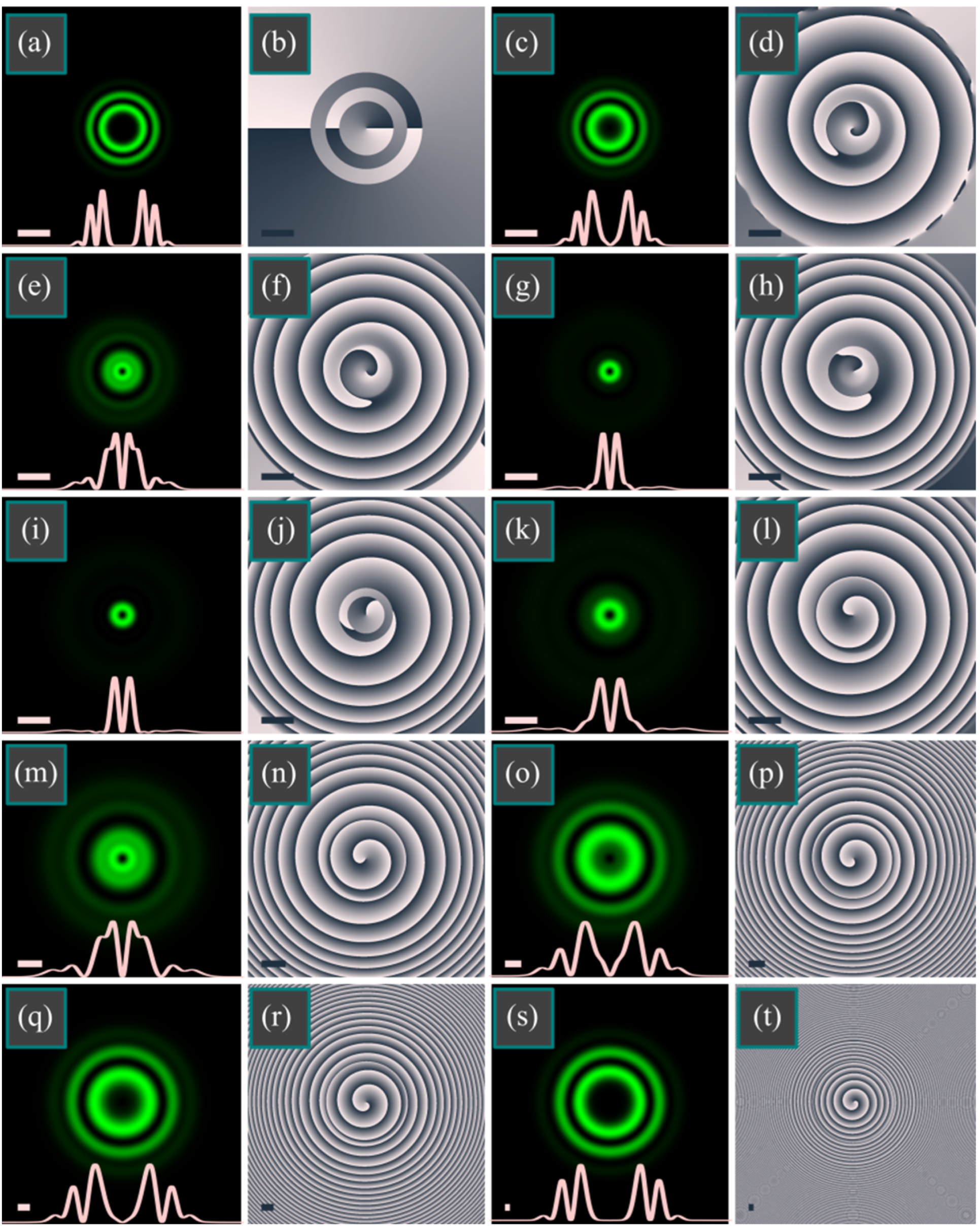
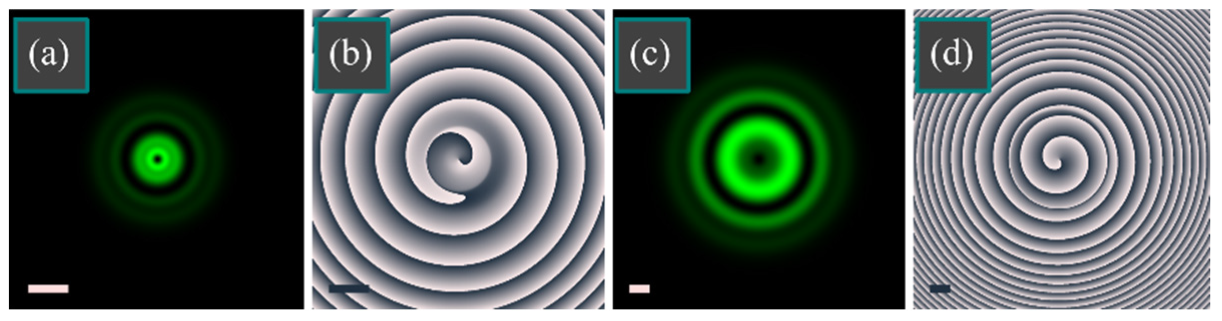
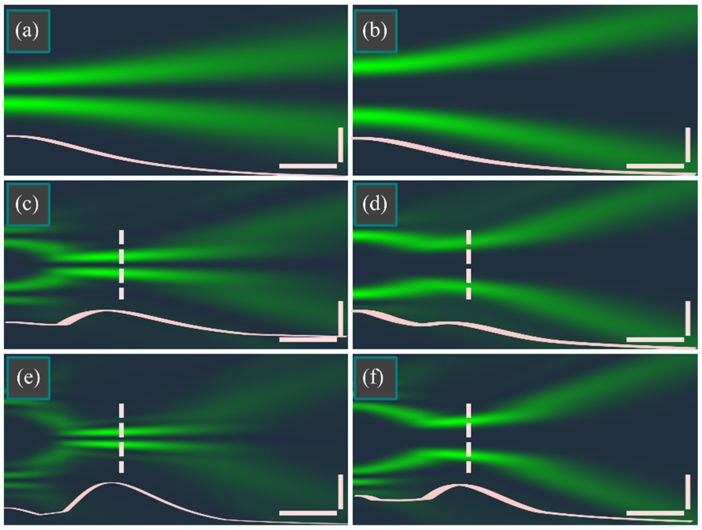
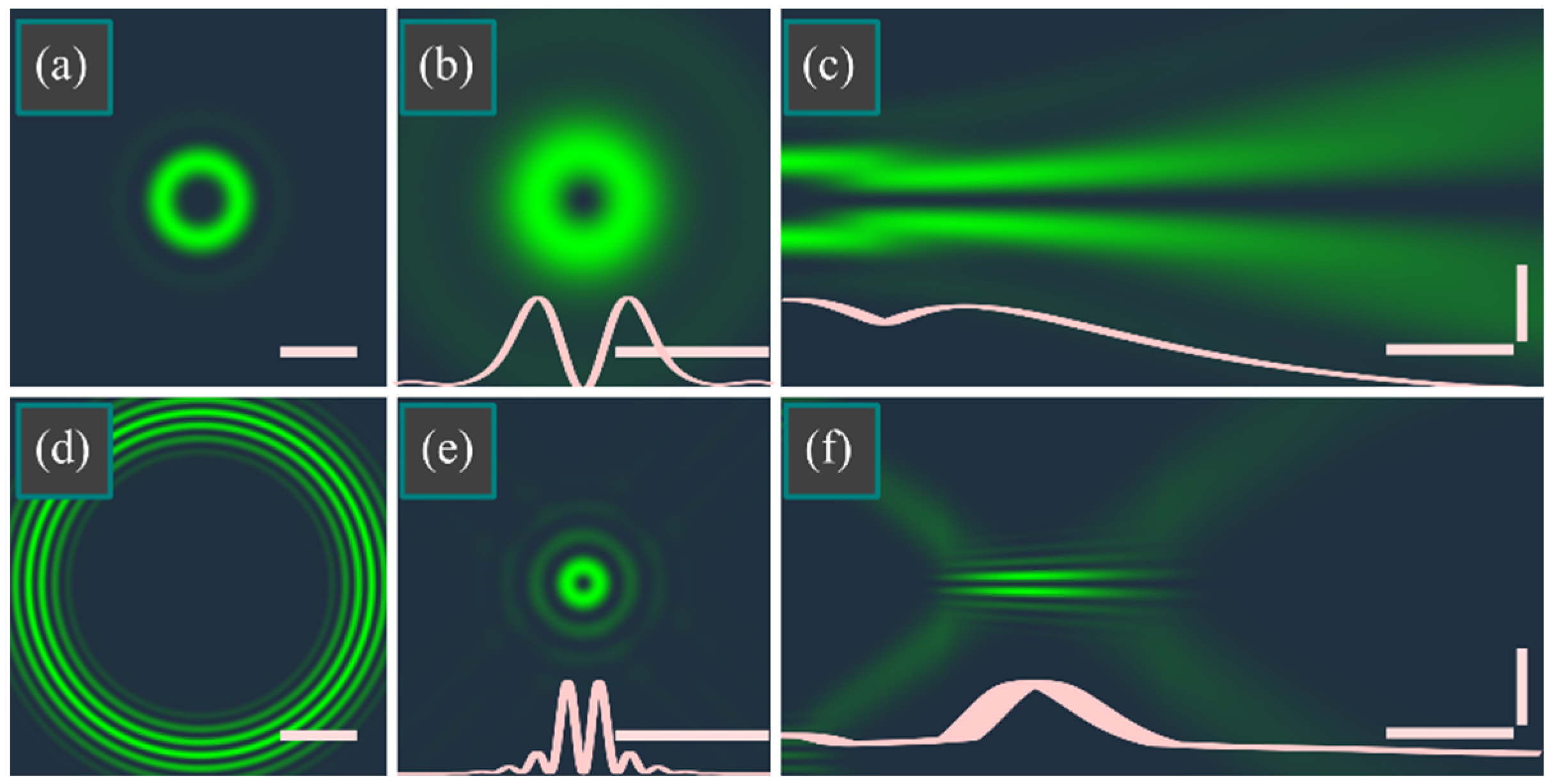
4. Numerical Simulation

In this section, using the Fresnel transform of the LG beam from Equation (1), we compute the transverse intensity and phase distributions at different distances from the initial (waist) plane. We use the following parameters: wavelength λ = 532 nm, waist radius of the Gaussian beam w = 0.5 mm, azimuthal (upper) and radial (lower) indices of the associated Laguerre polynomial are m = 4 and n = 3, respectively. Figure 1 illustrates the intensity (columns 1 and 3) and phase (columns 2 and 4) distributions of the beam from Equation (1) at the following distances from the waist z/z0: 0 (Figure 1a,b), 1/4 (Figure 1c,d), 1/2 (Figure 1e,f), 3/4 (Figure 1g,h), 1 (Figure 1i,j), 1.5 (Figure 1k,l), 2 (Figure 1m,n), 3 (Figure 1o,p), 4 (Figure 1q,r), 10 (Figure 1s,t).
According to Figure 1, at the Rayleigh distance z0 from the waist, a single light ring is generated with its radius nearly equal to 0.4 mm. This is equivalent to focusing a Gaussian beam with a waist radius of 0.5 mm by a spherical lens with a very weak numerical aperture, nearly NA = 1.41w/z0 = 0.0005. Increasing the radial index n allows increasing NA several times. We note that a low numerical focusing aperture leads to a large depth of field since the depth of focus (DOF) is inverse proportional to the squared numerical aperture. We also note that in the initial plane, the first light ring has a radius almost twice as large as the waist radius and equal to nearly 0.9 mm. The conventional LG beam with a waist radius of 0.5 mm would have such a radius at the topological charge of 3, whereas the LG beam from Equation (1) has the topological charge mn = 4 − 3 = 1. Therefore, modeling confirms that the beams (1) have an enlarged dark area in the initial plane (Figure 1a), and at the Rayleigh distance, a focal spot is formed in the form of a narrow light ring (Figure 1i) almost without side lobes. Although to be precise, focusing (maximum intensity on the ring) takes place at a distance of 0.75z0 (Figure 1g) and 2.38 times greater than the maximum intensity on the ring in the initial plane (Figure 1a). At the Rayleigh distance, the intensity is slightly less (Figure 1i) and 2.37 times greater than in the initial plane. It can also be seen from Figure 1 that the far-field intensity (Figure 1s) coincides with the initial intensity (Figure 1a). This confirms the Fourier invariance property (4) of beams (1). As to the phase evolution, it is seen in Figure 1 that in all transverse planes, the phase contains an (mn)th-order singularity in the center since all the terms in Equation (15) are proportional to exp(ilφ). In addition, the vortex phase rotates on propagation, and the wavefront acquires an additional parabolic shape due to converging and diverging.
Figure 1 was obtained by the numerical Fresnel transform, implemented as a convolution using the fast Fourier transform (implemented in the SciPy library for the Python language). To confirm the expansion (13) into a superposition of the conventional LG beams, Figure 2 illustrates the same patterns as in Figure 1e,f,o,p, but computed analytically via the Laguerre polynomials and the expansion coefficients (13). It is seen that Figure 2a–d are quite identical to Figure 1e,f,o,p, respectively.
Now when Equation (13) is tested, we can use Equation (15) for computing the longitudinal intensity distributions of the beam from Equation (1) and investigate how the beam transforms when the radial and azimuthal indices vary. Figure 3 illustrates these distributions for the following parameters: wavelength λ = 532 nm, waist radius w = 0.5 mm, radial and azimuthal indices (n, m) are, respectively, (0, 1) (Figure 3a), (0, 4) (Figure 3b), (3, 4) (Figure 3c), (3, 7) (Figure 3d), (6, 7) (Figure 3e), (6, 10) (Figure 3f). For these values, the topological charge of the beams in the left column of Figure 1 is 1, whereas, for the beams from the right column, it is equal to 4. Since n = 0 in Figure 3a,b, these beams reduce to the conventional single-ringed LG beams of the topological charge m. These beams do not possess the autofocusing property. At n = 3 and n = 6, Figure 3 confirms that the beams are autofocusing, although the pronounced focus, when the intensity decays more than two times from its maximum, is only at (n, m) = (6, 7). The depth-of-field, in this case, is almost equal to the Rayleigh length: DOF ≈ 0.9z0. In addition, Figure 3 confirms that the radial index affects the size of the dark area inside the main light ring, but in the initial plane and the far field. On the contrary, in the plane of the autofocus, the beam is narrower than the conventional LG beam in its waist (the beam in Figure 3e is narrower than the beam in Figure 3c, which is narrower than the conventional LG beam from Figure 3a). To demonstrate to what extent we can increase or decrease the dark area in focus, Figure 4 depicts the beam (1) with a unit topological charge but with small and large index values: (n, m) = (1, 2) (Figure 4a–c) and (n, m) = (20, 21) (Figure 4d–f). At (n, m) = (1, 2), the focal distance decreases to 0.7z0, and the ring diameter is nearly equal to the ring diameter of the conventional LG beam with the charge of 1 in its waist, i.e., 0.7 mm (21/2w). At (n, m) = (20, 21), the beam is much narrower in the focal plane: its main ring has a diameter of nearly 0.2 mm. The depth-of-field, in this case, is nearly equal to the half of Rayleigh length: DOF ≈ 0.5z0. We believe that further increasing of the values n and m will lead to further decreasing (theoretically unlimited) of the ring radius in the autofocus plane. Still, in this case, the light beam becomes nonparaxial, and we cannot use Equation (15) and the Fresnel transform to estimate the ring diameter in the focal plane.

5. Conclusions

Here, we investigated a new type of Laguerre-Gaussian beam with autofocusing. At a fixed value of the topological charge l of these beams, changing the radial index n of the Laguerre polynomial allows controlling the focusing degree of these beams at the Rayleigh distance from the waist. Although the numerical aperture of such focusing is not high (inversely proportional to the Rayleigh distance z0), the depth of field, in this case, is significant (proportional to z0). Another interesting property of these beams, in contrast to the conventional Laguerre-Gaussian beams, is that at the zero topological charge (l = 0), the beams (5) generate in the focus of a spherical lens a light ring. The diameter of this ring can be adjusted by changing the radial index n and the ratio of the lens focal length and the Rayleigh distance (f/z0). This property of these beams can be used for simultaneous optical trapping of several metallic microparticles into the increased dark area of the light ring in the focus of the spherical lens. We note that the Bessel or Bessel-Gaussian [20] beams are also able to generate a light ring in focus at a zero topological charge. However, the Bessel and Bessel-Gaussian beams are not Fourier-invariant and generate in the focus of one light ring. The investigated here LG beams are Fourier-invariant and can generate in the focus several light rings with nearly the same intensity.

Author Contributions

Conceptualization, V.V.K.; methodology, V.V.K. and E.G.A.; software, A.A.K. and A.A.S.; validation, V.V.K. and E.G.A.; formal analysis, V.V.K.; investigation, E.G.A. and A.A.K.; resources, V.V.K.; data curation, V.V.K.; writing—original draft preparation, V.V.K.; writing—review and editing, V.V.K. and E.G.A.; visualization, A.A.K. and A.A.S.; supervision, V.V.K.; project administration, V.V.K.; funding acquisition, V.V.K. and A.A.K. All authors have read and agreed to the published version of the manuscript.

Funding

The work was funded by the Russian Science Foundation under grant #22-12-00137.

Institutional Review Board Statement

Not applicable.

Informed Consent Statement

Not applicable.

Data Availability Statement

Not applicable.

Acknowledgments

We acknowledge the support of the RF Ministry of Science and Higher Education within a government project of the FSRC “Crystallography and Photonics” RAS.

Conflicts of Interest

The authors declare no conflict of interest. The funders had no role in the design of the study; in the collection, analyses, or interpretation of data; in the writing of the manuscript, or in the decision to publish the results.

References

  1. Prentice, P.A.; MacDonald, M.P.; Frank, T.G.; Cuschieri, A.; Spalding, G.C.; Sibbett, W.; Campbell, P.A.; Dholakia, K. Manipulation and filtration of low index particles with holographic Laguerre-Gaussian optical trap arrays. Opt. Express 2004, 12, 593–600. [Google Scholar] [CrossRef] [PubMed]
  2. Doster, T.; Watnik, A.T. Laguerre–Gauss and Bessel–Gauss beams propagation through turbulence: Analysis of channel efficiency. Appl. Opt. 2016, 55, 10239–10246. [Google Scholar] [CrossRef] [PubMed]
  3. Ferlic, N.A.; van Iersel, M.; Paulson, D.A.; Davis, C.C. Propagation of Laguerre-Gaussian and Im Bessel beams through atmospheric turbulence: A computational study. In Proceedings of the Laser Communication and Propagation through the Atmosphere and Oceans IX, Online, 22 August 2020; p. 115060H. [Google Scholar] [CrossRef]
  4. Abad, M.G.G.; Mahmoudi, M. Laguerre-Gaussian modes generated vector beam via nonlinear magneto-optical rotation. Sci. Rep. 2021, 11, 5972. [Google Scholar] [CrossRef]
  5. Cao, M.; Yu, Y.; Zhang, L.; Ye, F.; Wang, Y.; Wei, D.; Zhang, P.; Guo, W.; Zhang, S.; Gao, H.; et al. Demonstration of CNOT gate with Laguerre Gaussian beams via four-wave mixing in atom vapor. Opt. Express 2014, 22, 20177–20184. [Google Scholar] [CrossRef]
  6. Dedecker, P.; Muls, B.; Hofkens, J.; Enderlein, J.; Hotta, J. Orientational effects in the excitation and de-excitation of single molecules interacting with donut-mode laser beams. Opt. Express 2007, 15, 3372–3383. [Google Scholar] [CrossRef] [PubMed]
  7. Bokor, N.; Iketaki, Y.; Watanabe, T.; Fujii, M. Investigation of polarization effects for high-numerical-aperture first-order Laguerre-Gaussian beams by 2D scanning with a single fluorescent microbead. Opt. Express 2005, 13, 10440–10447. [Google Scholar] [CrossRef] [PubMed]
  8. Allen, L.; Beijersbergen, M.W.; Spreeuw, R.J.C.; Woerdman, J.P. Orbital angular momentum of light and the transformation of Laguerre–Gaussian laser modes. Phys. Rev. A 1992, 45, 8185–8189. [Google Scholar] [CrossRef] [PubMed]
  9. Zhou, G.; Ru, G. Orbital angular momentum density of an elegant Laguerre–Gaussian beam. Prog. Electromagn. Res. 2013, 141, 751–768. [Google Scholar] [CrossRef]
  10. Abramochkin, E.; Razueva, E.; Volostnikov, V. General astigmatic transform of Hermite–Laguerre–Gaussian beams. J. Opt. Soc. Am. A 2010, 27, 2506–2513. [Google Scholar] [CrossRef] [PubMed]
  11. Kovalev, A.A.; Kotlyar, V.V.; Porfirev, A.P. Asymmetric Laguerre-Gaussian beams. Phys. Rev. A 2016, 93, 063858. [Google Scholar] [CrossRef]
  12. Kotlyar, V.V.; Abramochkin, E.G.; Kovalev, A.A.; Savelyeva, A.A. Product of two Laguerre–Gaussian beams. Photonics 2022, 9, 496. [Google Scholar] [CrossRef]
  13. Bisson, J.F.; Senatsky, Y.; Ueda, K.I. Generation of Laguerre-Gaussian modes in Nd:YAG laser using diffractive optical pumping. Laser Phys. Lett. 2005, 2, 327–333. [Google Scholar] [CrossRef]
  14. Lin, D.; Daniel, J.M.O.; Clarkson, W.A. Controlling the handedness of directly excited Laguerre–Gaussian modes in a solid-state laser. Opt. Lett. 2014, 39, 3903–3906. [Google Scholar] [CrossRef] [PubMed]
  15. Thirugnanasambandam, M.P.; Senatsky, Y.; Ueda, K. Generation of very-high order Laguerre-Gaussian modes in Yb:YAG ceramic laser. Laser Phys. Lett. 2010, 7, 637–643. [Google Scholar] [CrossRef]
  16. Wang, M.; Ma, Y.; Sheng, Q.; He, X.; Liu, J.; Shi, W.; Yao, J.; Omatsu, T. Laguerre-Gaussian beam generation via enhanced intracavity spherical aberration. Opt. Express 2021, 29, 27783–27790. [Google Scholar] [CrossRef] [PubMed]
  17. Abramochkin, E.; Volostnikov, V. Beam transformations and nontransformed beams. Opt. Commun. 1991, 83, 123–135. [Google Scholar] [CrossRef]
  18. Matsumoto, N.; Ando, T.; Inoue, T.; Ohtake, Y.; Fukuchi, N.; Hara, T. Generation of high-quality higher-order Laguerre-Gaussian beams using liquid-crystal-on-silicon spatial light modulators. J. Opt. Soc. Am. A 2008, 25, 1642–1651. [Google Scholar] [CrossRef] [PubMed]
  19. Graham, R.L.; Knuth, D.E.; Patashnik, O. Concrete Mathematics; Addison-Wesley: Boston, MA, USA, 1994. [Google Scholar]
  20. Gori, F.; Guattari, G.; Padovani, C. Bessel-Gauss beams. Opt. Commun. 1987, 64, 491–495. [Google Scholar] [CrossRef]
Figure 1. Intensity (columns 1 and 3) and phase distributions (columns 2 and 4) of the LG beam from Equation (1) in different transverse planes z/z0 = 0 (a,b), 1/4 (c,d), 1/2 (e,f), 3/4 (g,h), 1 (i,j), 1.5 (k,l), 2 (m,n), 3 (o,p), 4 (q,r), 10 (s,t). Other computation parameters are: wavelength λ = 532 nm, waist radius of the Gaussian beam w = 0.5 mm, azimuthal (upper) and radial (lower) indices of the associated Laguerre polynomial are m = 4 and n = 3, respectively. Plots in the intensity distributions show the intensity cross-sections. Scale marks in the left lower corners (light in columns 1 and 3 and dark in columns 2 and 4) show 1 mm.
Photonics 09 00708 g001
Figure 2. The same intensity (a,c) and phase (b,d) distributions as in Figure 1e,f (a,b) and as in Figure 1o,p (c,d), but obtained analytically by Equation (7) using the expansion coefficients (8).
Photonics 09 00708 g002
Figure 3. Longitudinal intensity distributions of the beam from Equation (1) with the topological charge of 1 (a,c,e) and 4 (b,d,f) when the radial (lower) index n of the associated Laguerre polynomial is as 0 (a,b), 3 (c,d), 6 (e,f). Below each distribution, a longitudinal intensity cross-section is shown. Horizontal and vertical scale marks denote, respectively, z0/2 and 1 mm. Transverse dashed line denotes the autofocus plane z = z0.
Photonics 09 00708 g003
Figure 4. Transverse initial (a,d) and focal (b,e) intensity distributions, as well as the longitudinal intensity distributions (c,e) of the beam from Equation (1) with the (n, m) = (1, 2) (ac) and with the (n, m) = (20, 21) (d,f). Curves (b,c,e,f) show the intensity cross-sections. Horizontal scale marks in the transverse patterns denote 1 mm. Horizontal and vertical scale marks in longitudinal patterns denote z0/2 and 1 mm, respectively.
Photonics 09 00708 g004
Publisher’s Note: MDPI stays neutral with regard to jurisdictional claims in published maps and institutional affiliations.

