Communication

A 245 GHz Real-Time Wideband Wireless Communication Link with 30 Gbps Data Rate

1
Commonwealth Scientific and Industrial Research Organization (CSIRO), Sydney, NSW 2070, Australia
2
Global Big Data Technology Center (GBDTC), University of Technology Sydney (UTS), Sydney, NSW 2007, Australia
*
Author to whom correspondence should be addressed.
Photonics 2022, 9(10), 683; https://doi.org/10.3390/photonics9100683
Submission received: 5 August 2022 / Revised: 12 September 2022 / Accepted: 15 September 2022 / Published: 22 September 2022
(This article belongs to the Special Issue Terahertz (THz) Science in Advanced Materials, Devices and Systems)

Abstract

:
This paper presents a 245 GHz wireless communications system with a data rate of 30 Giga bits per second (Gbps) at a 1.2 m distance, which proves the potential for future high-speed communications beyond 5G technology. The system consists of low-complexity and real-time base-band modules to provide the high-speed wideband signal processing capability. Multi-channel base-band signals are combined and converted to 15.65 ± 6.25 GHz wideband intermediate frequency (IF) signals. A novel 245 GHz waveguide bandpass filter (BPF) with low loss and high selectivity is designed and applied to a terahertz (THz) front-end for image rejection and noise suppression. Configuration of the base-band, IF, and THz front-end modules is also given in detail. The 245 GHz wireless communication link is demonstrated over a distance of 1.2 m.

1. Introduction

The ever-increasing demands for high-speed wireless communications keep pushing wireless systems toward a higher frequency regime [1,2]. The research in wireless communications has now moved from mm-wave towards sub-terahertz (THz)/THz frequencies, where there are abundant spectral vacancies [3]. It is anticipated that THz communications will be the choice of future space communication technology because there is no or very little atmospheric attenuation in space, potentially facilitating long-range communication between satellites, satellites to constellations, or high-altitude aircrafts/airbuses [4,5,6,7,8].
Early progress in and developments of THz wireless communications have been reported in [9,10,11,12,13] based on electronics and optical front-end hardware. In [12], a 240 GHz optical wireless communication system is demonstrated with a maximum data rate of 100 Gbps, and a 300-GHz-band 120-Gb/s wireless link is reported in [13] with InP-based high-electron-mobility-transistor (InP-HEMT) front-ends. However, these high-speed base-band signals are generated from benchtop instruments such as an arbitrary waveform generator (AWG) and received by oscilloscopes for data analysis or offline processing on the receiver side while the data generating and processing tasks in the real communication systems are performed by digital circuit modules such as FPGAs. In recent years, several real-time THz wireless systems achieving multi-Gbps data rates have been published [14,15,16,17,18,19,20], which is more suitable for practical application scenarios compared with instrument-based demonstrations. One major solution of the real-time communication system is a simple modulation scheme, typically on-off keying (OOK) or binary phase-shift keying (BPSK), over a large frequency bandwidth [14,15,16]. These systems demonstrate a high data rate with simple base-band configuration, but their spectrum efficiency is relatively low compared with higher order modulation schemes, namely quadrature phase shift keying (QPSK) and quadrature amplitude modulation (QAM). Another approach that has been reported is the use of modulations of high spectral efficiency within a narrow bandwidth [18,19,20]. In particular, a real-time THz wireless transmission at 300 GHz is reported in [18], with QPSK modulation and digital beamforming implemented, featuring a 3 Giga bits per second (Gbps) data rate within the 1.5 GHz bandwidth. In [19,20], a 220 GHz solid-state dual-carrier wireless link was demonstrated based on 16QAM and 64QAM across a frequency range of 5.2 GHz, demonstrating a communication speed at 20.8 and 31.2 Gbps, respectively. These systems, however, have relative operational bandwidths lower than 3%, and hence the full potential of the large THz frequency spectrum capacity has not been explored. To achieve high-order modulation in a wide frequency range, on the other hand, major challenges need to be tackled on the base-band and THz front-end modules. First, low-complexity algorithms and implementation in the base-band module are essential with system resource and timing optimization. Additionally, an intermediate frequency (IF) stage is required to accommodate multiple channels of base-band signals to increase the spectral capacity. Furthermore, high-frequency selectivity is also desirable to suppress background noise and mirror image interferences.
In this paper, we present the development of a high-speed, real-time wideband wireless communication system operating at 245 GHz over a distance of 1.2 m. The 16QAM modulation scheme is used in four base-band channels, which occupy the 10 GHz frequency band in total, to achieve an overall 30 Gbps data rate. Low-complexity implementation with low resource usage and a high frequency of the system clock on the field programmable gate array (FPGA) is applied in the base-band development. Real-time experimental test results are also given. Additionally, a low-loss, high-selectivity waveguide bandpass filter (BPF) is developed for the THz front-end to eliminate spurious interferences and reduce the background noise power level, and therefore the signal-to-noise ratio (SNR) of the receiver is optimized.

2. System Architectures and Configurations

Figure 1 shows the configuration of the THz wireless communication system, where the transmitter and receiver are separated by 1.2 m in the wireless communication demonstration setup. Both the transmitter and the receiver are composed of three modules: base-band module, IF module, and THz front-end module. The base-band module on the transmitter side has 4 channels of in-phase and quadrature-phase (I/Q) outputs, with each I/Q output generating signals at a speed of 7.5 Gbps within the 2.5 GHz bandwidth. Hence, the total data rate and bandwidth of the base-band modules are 30 Gbps and 10 GHz, respectively. The IF modules are used for frequency up- and down-conversion between the 0–2.5 GHz base-band signals and 15.65 GHz IF frequency. The bandwidth of the IF module is 12.5 GHz, with a 2.5 GHz guard band between different channels. The IF modules are connected to the 245 GHz THz front-end modules for frequency up-conversion, transmission, detection, and demodulation. A pair of horn antennas with 25 dBi gain are connected to the THz transmitter and receiver for wireless communications while the communication distance can be further improved if higher-gain antennas are used.

3. Base-Band Module with 30 Gbps Data Rate

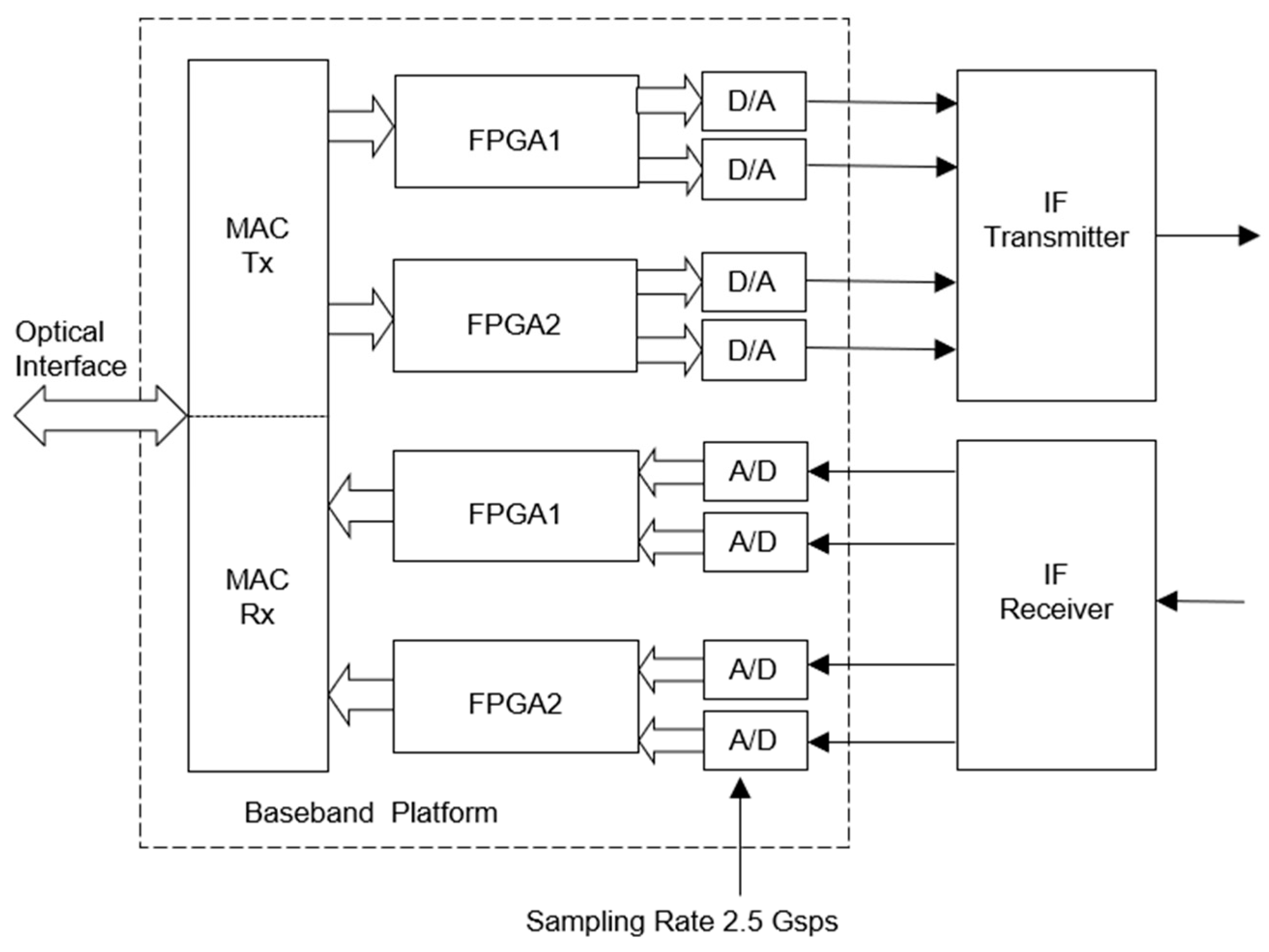
The base-band module is the key component of the high-speed backhaul communication system. The structure of the base-band module in this work is shown in the dashed box of Figure 2. The digital base-band module is composed of two FPGAs, each capable of processing a 15 Gbps data rate.
On the transmitter side, typical digital signal processing (DSP) modules include a low-density parity check (LDPC) encoder, modulation, and transmitter filter. With a 1.875 Gsps symbol rate and 2.5 Gsps sampling rate, sample rate conversion (SRC) with an up-sampling ratio of 4/3 is performed by the transmitter filter with root-raised-cosine (RRC) pulse shaping. Three symbols form a symbol group, each generating an RRC pulse and outputting four samples every three symbol intervals. On the receiver side, there is synchronization, channel estimation, the receiver filter, demodulation, and the LDPC decoder [21]. The receiver filter performs SRC, channel equalization, and I/Q mismatch compensation at the same time. After channel and I/Q mismatch estimation using the training sequence embedded in the transmission preamble, two equalizer impulse responses are constructed, with each being applied to the real part and imaginary part of the received signal samples, respectively, for I/Q mismatch compensation while SRC with a down-sampling ratio of ¾ is implemented by outputting three equalized and I/Q mismatch compensated symbols every four sampling periods.
Therefore, the overall implementation complexity is significantly reduced compared to conventional designs [22]. There is no feedback between the processing modules and each module does not require huge data storage. All modules are run by the parallel pipelined processing. Adopting this kind of simple structure, all modules can be implemented in real-time using affordable hardware. The base-band DSP platforms adopt Xilinx Virtex 7-690t FPGA devices [23]. The resource usage for all DSP modules is shown in Table 1, which shows that the usage rate of some typical cells is reasonable compared with the total resources and it is not difficult to meet the timing requirements for the high-frequency system clock (312 MHz).
To prevent spectral overlap between two adjacent channels at the IF stage, a raised-cosine pulse shaping with a roll-off factor of 0.133 is implemented at each digital base-band. Therefore, the bandwidth of each IF channel is 2.125 GHz to ensure the adjacent IF channels are separated with sufficient inter-channel suppression.
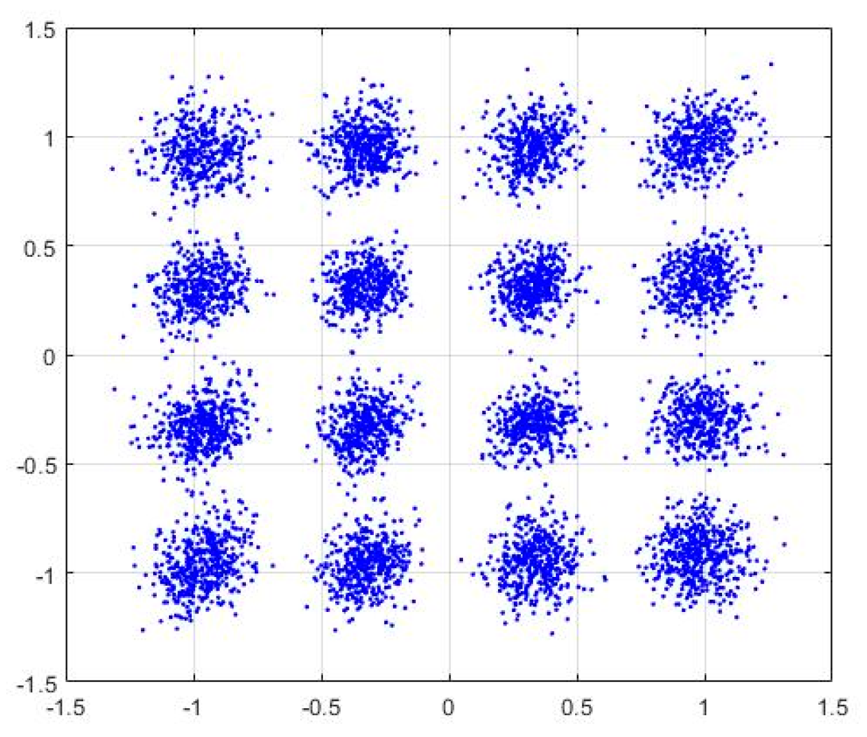
The digital-to-analog converters (DACs) of AD9739 [24] and digital-to-analog converters (ADCs) of EV10AQ190A [25] are adopted for the base-band platforms. The sampling rate for each channel of DAC or ADC is 2.5 Giga-samples per second (Gsps) and the data symbol rate is 1.875 Gsps for each base-band signal. The four bits are mapped into one data symbol using 16QAM. Therefore, the total data rate of four base-band signals is 1.875 × 4 × 4 = 30 Gbps. At the transmitter side, traffic streams generated by the Spirent TestCenter [26] are the pseudo-random bit sequence with a 128 bytes packet size. At the receiver side, the received Ethernet traffic streams are fed back to the Spirent TestCenter, and the BER result can be recorded from the user window of the Spirent TestCenter. Figure 3 shows the measured 16QAM constellations of the base-band platform loopback via direct DACs and ADCs connection, with an error vector magnitude (EVM) result of 4%. From this result, we can ensure that the signal processing produces a superb performance before connecting with the IF module and THz front-end.

4. IF Module Configuration

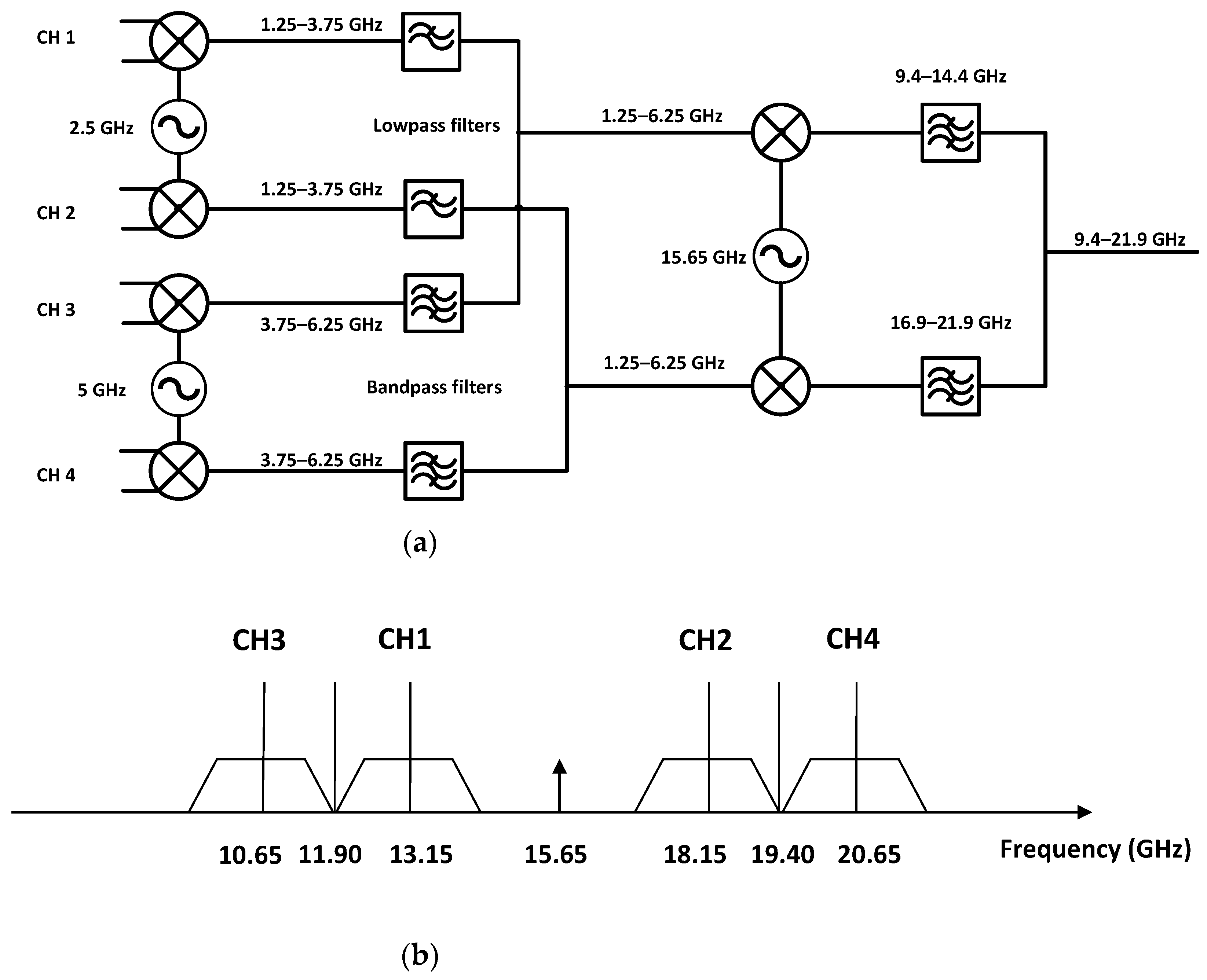
To achieve a high data rate and exploit the potential of the THz wide frequency vacancy, IF frequency modulation is needed to convert multiple base-band channels to a higher frequency with sufficient spectral capacity. Figure 4a shows the schematic block diagram of the IF up-converter module while the down-converter has a symmetric structure. Any two of four IF channels connect with one FPGA platform and each chanel occupies the 2.5 GHz bandwidth. Four IF channels, marked as CH1 to CH4 in Figure 4, are up-converted to the IF frequency range of 15.65 ± 6.25 GHz via a two-stage frequency conversion configuration. In the first stage, CH1 and CH2 are modulated by a 2.5 GHz LO signal to the 1.25–3.75 GHz range while CH3 and CH4 are converted to the 3.75–6.25 GHz frequency. The up-converted CH1 is then combined with CH3 and up-converted to the lower side band (LSB) frequency of the second stage LO signal at 15.65 GHz, from 9.4 to 14.4 GHz, and CH2 in combination with CH4 are modulated to the upper side band (USB). The LSB and USB channels are then combined with the power coupler and connected to the interface of the THz front-end. Lowpass and bandpass filters are applied to individual channels for interference suppression. The spectrum assignment of the four channels in the IF operation frequency is shown in Figure 4b. The total IF operation frequency range is therefore 9.4 to 21.9 GHz, with 10 GHz of effective spectral occupancy. Compared with the systems without the IF conversion stage [18,19,20], the proposed approach features a larger bandwidth, which results in a higher data volume.
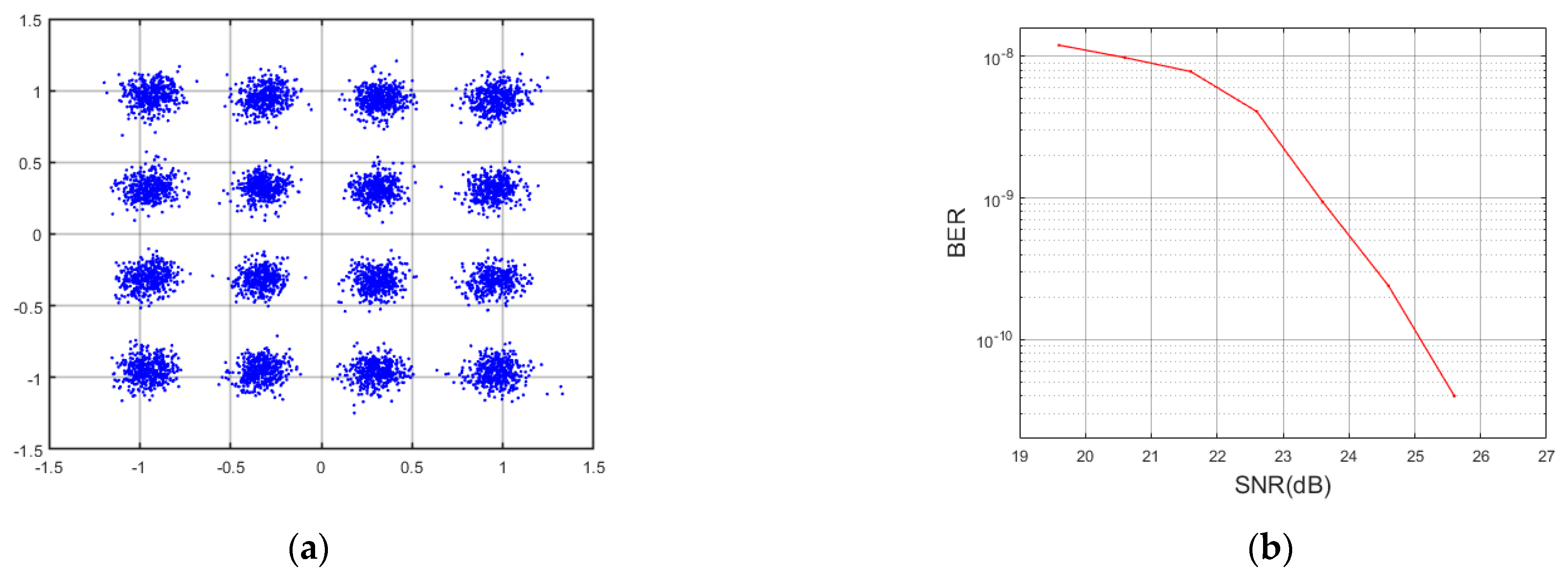
A loopback test was performed with direct connection of the base-band and IF modules, and the measured results are shown in Figure 5. The performance of the communication is evaluated based on the measured EVM and BER. In the case of averaging a large number of symbols, it is safe to assume that EVM (dB) = −SNR (dB) [27]. The measured constellation is shown in Figure 5a with an EVM value at −19.7 dB (10.3%), equivalent to SNR at +19.7 dB. The BER test with real-time Ethernet traffic from the Spirent TestCenter is also measured with the variation of SNR, as shown in Figure 5b, which shows a BER around 10−8 when SNR is at 19.7 dB.

5. THz Front-End Module

The THz front-end configuration is shown in Figure 6. A pair of sub-harmonics mixers (SHMs) are used on the transmitter and receiver side for frequency up- and down-conversion, with a typical conversion loss of 8 dB and noise temperature of 1200 K. Both SHMs are pumped by 130 GHz LO signals, which are generated from benchtop signal generators, and multiplied by Virginia Diodes (VDI) frequency multiplier chain modules. A power amplifier is applied at the transmitter end to increase the output power of THz front-end. The amplifier has a gain of 26 dB and a saturation power around +14 dBm around the frequency of interest, as shown in Figure 7.
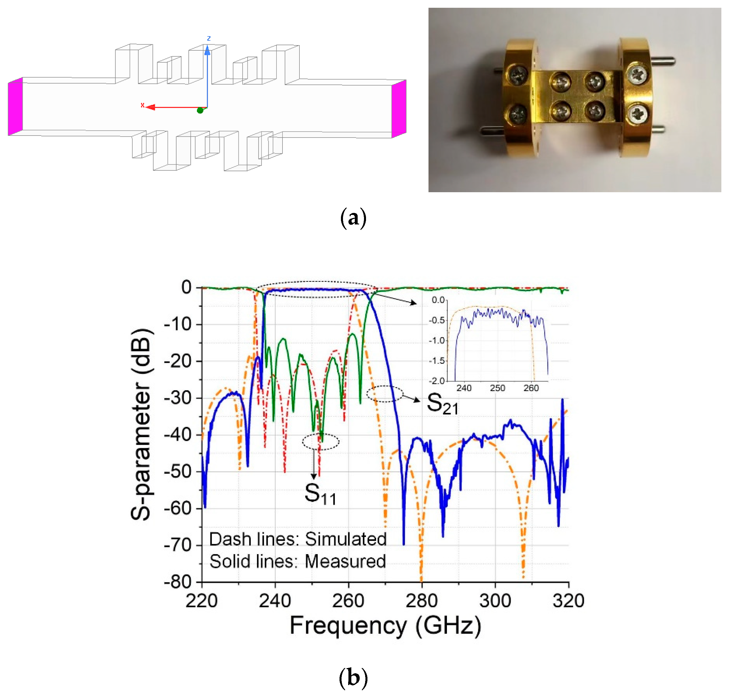
BPF is a key component for THz communication for the purpose of noise suppression and image rejection. A 5-order inline BPF is developed and applied to the THz front-end system as shown in Figure 8a, with a designed passband of 235–260 GHz. The filter is designed based on bandstop resonator pairs, in the form of E-plane stubs that resonate at the lower and upper stopbands of the desired passband frequency. The bandstop resonators provide sharp roll-off and out-of-band rejection, and they can be controlled independently without introducing interference. Therefore, the proposed BPF has high design flexibility for different bandwidth requirements. Figure 8b shows the simulated and measured S-parameters’ comparison of the 5th-order BPF. The insertion loss is around 0.35 dB in the passband from 238 to 265 GHz, and the suppression in the mirror image frequency (270 GHz and above) is better than 30 dB.

6. System Measurement Results

The system test of the wireless communication link is shown in Figure 9, in which the transmitter and receiver are positioned within a line-of-sight range. Figure 10 shows the constellation of the wireless link, and the measured EVM is 12.7%, which is slightly higher than the result from the IF loopback test, 10.3%, due to the inclusion of the THz front-end and the path loss. The measurement result suggests a high quality of the wireless communication link. A comparison was made between the proposed communication system and recent work reported at similar frequencies, as shown in Table 2. It is shown that the proposed system has achieved a high speed with a relatively lower sampling rate, owing to the large bandwidth utility. The performance of the system can be further improved in terms of the communication distance with the application of antennas of higher gain and dual polarization and power combining at the transmitter end.

7. Conclusions

A 245 GHz real-time wideband wireless communication link with a 30 Gbps data rate is presented in this paper. The 16QAM modulation scheme was used in four base-band channels with low-complexity algorithms and FPGA resource consumption. IF modules operating at 15.65 GHz were applied to combine the base-band signals for further frequency conversion and signal transmission at 245 GHz. THz BPF was also adopted in the system to reduce the interference from the mirror image signal and background noise. The measured EVM at the base-band, IF, and THz front-end reached 4%, 10.3%, and 12.7%, respectively, demonstrating a high-quality wireless communication link at a distance of 1.2 m. The proposed THz wireless system demonstrates its potential for the application of next-generation communication systems, namely indoor wireless data transfer and inter-satellite high-speed communications.

Author Contributions

Conceptualization, X.H.; Data curation, H.Z.; Funding acquisition, J.D.; Investigation, T.Z., H.Z. and H.S.; Methodology, T.Z., H.Z., X.H., J.P. and K.S.; Project administration, T.Z. and J.D.; Supervision, J.D. and J.G.; Validation, H.Z.; Visualization, K.S.; Writing—original draft, T.Z. and H.Z.; Writing—review & editing, X.H., H.S., J.P. and K.S. All authors have read and agreed to the published version of the manuscript.

Funding

Commonwealth Scientific and Industrial Research Organisation (CSIRO) Space Technology Future Science Platform Project ST-R2-03.

Institutional Review Board Statement

Not applicable.

Informed Consent Statement

Not applicable.

Data Availability Statement

The data presented in this study are available on request from the corresponding author.

Conflicts of Interest

The authors declare no conflict of interest.

References

  1. Fettweis, G.; Alamouti, S. 5G: Personal mobile internet beyond what cellular did to telephony. IEEE Commun. Mag. 2014, 52, 140–145. [Google Scholar] [CrossRef]
  2. Khan, L.U.; Yaqoob, I.; Imran, M.; Han, Z.; Hong, C.S. 6G wireless systems: A vision, architectural elements, and future directions. IEEE Access 2020, 8, 147029–147044. [Google Scholar] [CrossRef]
  3. Jiang, W.; Han, B.; Habibi, M.A.; Schotten, H.D. The road towards 6G: A comprehensive survey. IEEE Open J. Commun. Soc. 2021, 2, 334–366. [Google Scholar] [CrossRef]
  4. Federici, J.; Moeller, L. Review of terahertz and subterahertz wireless communications. J. Appl. Phys. 2010, 107, 6. [Google Scholar] [CrossRef]
  5. Kleine-Ostmann, T.; Nagatsuma, T. A review on terahertz communications research. J. Infrared Millim. Terahertz Waves 2011, 32, 143–171. [Google Scholar] [CrossRef]
  6. Nagatsuma, T.; Ducournau, G. Advances in terahertz communications accelerated by photonics. Nat. Photonics 2016, 10, 371–379. [Google Scholar] [CrossRef]
  7. Song, H.J.; Nagatsuma, T. Present and future of terahertz communications. IEEE Trans. Terahertz Sci. Technol. 2011, 1, 256–263. [Google Scholar] [CrossRef]
  8. Akyildiz, I.F.; Han, C.; Hu, Z.; Nie, S.; Jornet, J.M. Terahertz band communication: An old problem revisited and research directions for the next decade. IEEE Trans. Commun. 2022, 70, 4250–4285. [Google Scholar] [CrossRef]
  9. Koenig, S. Wireless sub-THz communication system with high data rate enabled by RF photonics and active MMIC technology. In Proceedings of the 2014 IEEE Photonics Conference, Diego, CA, USA, 12–16 October 2014; pp. 414–415. [Google Scholar]
  10. Kallfass, I.; Boes, F.; Messinger, T.; Antes, J.; Inam, A.; Lewark, U.; Tessmann, A.; Henneberger, R. 64 Gbit/s transmission over 850 m fixed wireless link at 240 GHz carrier frequency. J. Infrared Millim. Terahertz Waves 2015, 36, 221–233. [Google Scholar] [CrossRef]
  11. Hara, S.; Takano, K.; Katayama, K.; Dong, R.; Lee, S.; Watanabe, I.; Sekine, N.; Kasamatsu, A.; Yoshida, T.; Amakawa, S.; et al. 300-GHz CMOS transceiver for terahertz wireless communication. In Proceedings of the 2018 Asia-Pacific Microwave Conference (APMC), Kyoto, Japan, 6–9 November 2018; pp. 429–431. [Google Scholar]
  12. Koenig, S.; Lopez-Diaz, D.; Antes, J.; Boes, F.; Henneberger, R.; Leuther, A.; Tessmann, A.; Schmogrow, R.; Hillerkuss, D.; Palmer, R.; et al. Wireless sub-THz communication system with high data rate. Nat. Photonics 2013, 7, 977–981. [Google Scholar] [CrossRef]
  13. Hamada, H.; Tsutsumi, T.; Matsuzaki, H.; Fujimura, T.; Abdo, I.; Shirane, A.; Okada, K.; Itami, G.; Song, H.J.; Sugiyama, H.; et al. 300-GHz-band 120-Gb/s wireless front-end based on InP-HEMT PAs and mixers. IEEE J. Solid-State Circuits 2020, 55, 2316–2335. [Google Scholar] [CrossRef]
  14. Wu, Q.; Lin, C.; Lu, B.; Miao, L.; Hao, X.; Wang, Z.; Jiang, Y.; Lei, W.; Den, X.; Chen, H.; et al. A 21 km 5 Gbps real time wireless communication system at 0.14 THz. In Proceedings of the 2017 42nd International Conference on Infrared, Millimeter, and Terahertz Waves, Cancun, Mexico, 27 August–1 September 2017; pp. 1–2. [Google Scholar]
  15. Takahashi, H.; Kosugi, T. 10-Gbit/s BPSK modulator and demodulator for a 120-Ghz-band wireless link. IEEE Trans. Microw. Theory Tech. 2011, 59, 1361–1368. [Google Scholar] [CrossRef]
  16. Moghadami, S.; Hajilou, F. A 210 Ghz fully integrated OOK transceiver for short-range wireless chip-to- chip communication in 40 nm CMOS technology. IEEE Trans. Terahertz Sci. Technol. 2015, 5, 737–741. [Google Scholar] [CrossRef]
  17. Eissa, M.H.; Malignaggi, A. Wideband 240-Ghz transmitter and receiver in BICMOS technology with 25-Gbit/s data rate. IEEE J. Solid-State Circuits 2018, 53, 2532–2542. [Google Scholar] [CrossRef]
  18. Ntouni, G.D. Real-time experimental wireless testbed with digital beamforming at 300 GHz. In Proceedings of the 2020 European Conference on Networks and Communications (EuCNC), Dubrovnik, Croatia, 15–18 June 2020; pp. 271–275. [Google Scholar]
  19. Feng, Y. A 20.8-Gbps dual-carrier wireless communication link in 220-GHz band. China Commun. 2021, 18, 210–220. [Google Scholar] [CrossRef]
  20. Feng, Y.; Zhang, B.; Qiao, C.; Dai, B. A 220-GHz-band 31.2-Gbps dual-carrier real-time wireless link using 64-QAM modulation. In Proceedings of the 2021 14th UK-Europe-China Workshop on Millimetre-Waves and Terahertz Technologies (UCMMT), Lancaster, UK, 13–15 September 2021; pp. 1–3. [Google Scholar]
  21. Zhang, H.; Huang, X.J.; Guo, Y.J. A 20 Gbps digital modem for high speed wireless backhaul applications. In Proceedings of the 2017 IEEE 85th Vehicular Technology Conference (VTC Spring), Sydney, NSW, Australia, 4–7 June 2017; pp. 1–5. [Google Scholar]
  22. Zhang, H.; Huang, X.J.; Guo, Y.J. Low-complexity digital modem implementation for high-speed point-to-point wireless communications. In Proceedings of the 2018 18th International Symposium on Communications and Information Technologies (ISCIT), Bangkok, Thailand, 26–29 September 2018; pp. 16–21. [Google Scholar]
  23. Xilinx. Available online: https://www.xilinx.com/products/silicon-devices/fpga/virtex-7.html#productTable (accessed on 30 August 2022).
  24. Analog Devices. Available online: https://www.analog.com/en/products/ad9739.html (accessed on 30 August 2022).
  25. E2V. Available online: https://www.e2v.com/resources/account/download-datasheet/1735 (accessed on 30 August 2022).
  26. Spirent. Available online: https://www.spirent.com/assets/u/spirent_fx2_datasheet (accessed on 30 August 2022).
  27. Shafik, R.A.; Rahman, M.S.; Islam, A.R. On the extended relationships among EVM, BER and SNR as performance metrics. In Proceedings of the 2006 International Conference on Electrical and Computer Engineering, Dhaka, Bangladesh, 19–21 December 2006; pp. 408–411. [Google Scholar]
Figure 1. Configuration of the THZ wireless communication system.
Photonics 09 00683 g001
Figure 2. Structure of the proposed base-band module.
Photonics 09 00683 g002
Figure 3. Measured constellations of the base-band platform.
Photonics 09 00683 g003
Figure 4. (a) Schematic of the IF module, and (b) the frequency assignment of the base-band channels.
Photonics 09 00683 g004
Figure 5. (a) Measured constellation of the IF loopback system, and (b) BER in relation to the system SNR.
Photonics 09 00683 g005
Figure 6. Schematic block diagram of the THz front-end modules.
Photonics 09 00683 g006
Figure 7. (a) Measured S-parameter of the THz power amplifier and (b) its saturated output power.
Photonics 09 00683 g007
Figure 8. (a) Design and fabricated photo of the proposed THz BPF, and (b) its simulation and measurement results.
Photonics 09 00683 g008
Figure 9. Photograph of the 30 Gbps THz communication demonstration platform.
Photonics 09 00683 g009
Figure 10. Measured constellation of the 245 GHz wireless communication system.
Photonics 09 00683 g010
Table 1. Resource consumption of the FPGA modules.
Cell NameSlice LUTsSlice RegistersBlock RamsMultipliers
Used number289,095425,7726872276
Total433,200866,40014703600
Usage Rate66.37%49.1%46.7%63.2%
Table 2. Comparison of published THz real-time wireless communication links.
Ref.Freq (GHz)Bandwidth (GHz)Data Rate (Gbps)Modulation SchemeDAC/ADC
Sampling Rate (Gsps)
Distance (m)
[18]3001.53QPSK2.4560
[19]2205.220.816 QAM6.40.3/1030 *
[20]2205.231.264 QAM6.40.05
This work24512.53016 QAM2.51.2
* 0.3 m link presented in a lab environment with antenna gain at 22 dBi, and 1030 m in a field test with antenna gain at 58 dBi.
Publisher’s Note: MDPI stays neutral with regard to jurisdictional claims in published maps and institutional affiliations.