Communication

Two-Dimension Asymmetric Electromagnetically Induced Grating in Rydberg Atoms

1
Center for Quantum Sciences and School of Physics, Northeast Normal University, Changchun 130024, China
2
School of Science and Key Laboratory of Materials Design and Quantum Simulation, Changchun University, Changchun 130022, China
*
Author to whom correspondence should be addressed.
Photonics 2022, 9(10), 674; https://doi.org/10.3390/photonics9100674
Submission received: 2 September 2022 / Revised: 16 September 2022 / Accepted: 17 September 2022 / Published: 20 September 2022
(This article belongs to the Special Issue Optical Quantum Manipulation of Rydberg Atoms)

Abstract

:
We investigate the realization and manipulation of a two-dimension (2D), asymmetric, electromagnetically induced grating (EIG) in a sample of Rydberg atoms exhibiting the van der Waals ( v d W ) interactions. The scheme relies on the application of a strong control field and a weak probe field, with the former periodically modulated in a 2D plane and the latter incident perpendicular to the 2D plane. We find that the probe field can be diffracted into an asymmetric intensity distribution depending on the relevant modulation parameters of the control field, as well as the density and length of the atomic sample. In particular, higher-order diffraction intensities can be enhanced in different ways as the v d W interaction, modulation strength, or sample length is increased. It is also of interest that the asymmetric diffraction distribution can be shifted to different quadrants by choosing appropriate modulation phases of the control field. These results may be used to develop new photonic devices with asymmetric diffraction properties required in future all-optical networks.

1. Introduction

Studies on atomic coherence induced by coherent interactions between monochromatic light fields and multi-level atoms have resulted in many fascinating phenomena in the field of quantum optics, such as electromagnetically induced transparency (EIT) [1], coherent population trapping [2], and lasing without inversion [3]. As far as EIT is concerned, the quantum destructive interference between different transition pathways generated by a strong control field renders an originally opaque atomic medium transparent to a weak probe field. Owing to the nontrivial merits of low absorption and strong dispersion [4,5], EIT has been widely explored to manipulate light propagation properties in various atomic media, including slowing, storing, and switching an optical pulse [6,7,8,9,10,11]. Thus far, the EIT technique has become a pivotal method in modern quantum optics [12] and quantum information processing [13].
As another important effect based on atomic coherence, electromagnetically induced grating (EIG) was first proposed in 1998 by applying a standing-wave (SW) control field in an EIT medium [14,15]. In this case, a vertically incident probe field will form a far-field distribution (Fraunhofer diffraction) when it travels through this EIT medium, whose susceptibility now changes periodically in space. Compared with conventional gratings, EIGs are much easier to construct and, more importantly, tunable, e.g., by modulating the optical response of an atomic medium on demand with the SW control field. In particular, EIGs do not involve the complications related to manufacturing differences and material aging; hence, they may pave the way towards advanced manufacturing techniques and novel optical devices.
EIGs have been implemented in a variety of optical systems, including atomic gases [16,17,18,19], quantum wells [20,21], and quantum dots [22,23], to name only a few. Recently, attention has been paid to how to manipulate different EIGs for realizing and tailoring asymmetric diffraction patterns [18,19,21,24,25]. Such a nontrivial task becomes viable when the parity-time (PT) symmetry or anti-symmetry is utilized to realize out-of-phase spatial modulations on the absorption and dispersion properties by adjusting relevant driving parameters [26,27,28,29]. On the other hand, attention has been paid to how to convert one-dimension (1D) EIGs [16,17,18] to two-dimension (2D) EIGs [24,30,31,32]. This brings new degrees of freedom for modulating Fraunhofer diffraction and indicates a further step toward practical applications. It has also been proposed to realize distinctive EIGs by replacing normal atoms with Rydberg atoms [33,34], exhibiting a few unique features such as huge electric dipole moments, long radiative lifetimes, and strong dipole–dipole interactions [35,36,37]. As Rydberg atoms are driven into the EIT regime, dipole–dipole interactions will result in the cooperative optical nonlinearity manifesting itself as the dependence of the optical response on the probe field intensity and atomic density. Consequently, the Rydberg EIGs are very different from that realized in atomic gases without dipole–dipole interactions, whether in the 1D symmetric, 2D symmetric, or 1D asymmetric form [19,25,33,34].
To the best of our knowledge, 2D asymmetric Rydberg EIGs have not been examined yet owing to, e.g., an intractable technical difficulty in obtaining suitable spatial modulations of the SW control fields. This difficulty may be overcome by combining the spatial modulation method in Ref. [24] and that in Ref. [26] with respect to the amplitude and frequency of a control field, respectively. Such a spatially correlated modulation is adopted here to realize a 2D asymmetric EIG in a sample of Rydberg atoms driven by a control field applied in the x y plane and a probe field incident along the z direction (see Figure 1a). Our numerical simulations show that the probe field exhibits an asymmetric intensity distribution in its far-field Fraunhofer diffraction after traveling through the sample of Rydberg atoms interacting via a van der Waals ( v d W ) potential, and it is viable to control the diffraction intensity distribution by modulating a few critical parameters of the control field and the atomic sample. To be more specific, we can (i) enhance higher-order diffraction intensities in certain quadrants by increasing the modulation strength or the sample length, and ( i i ) shift the asymmetric diffraction distribution to different quadrants by choosing appropriate modulation phases of the control field; both are promising for potential applications.

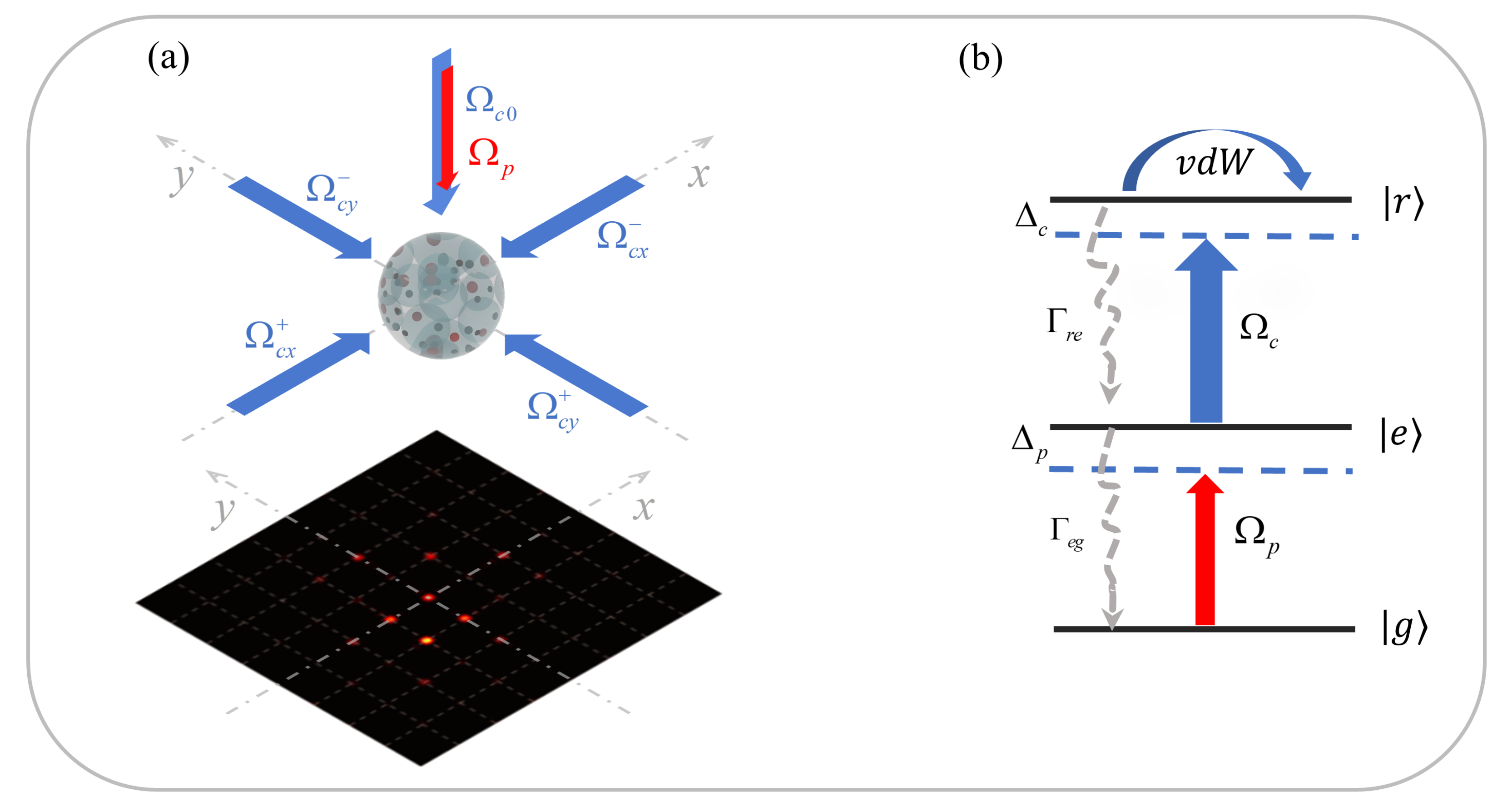
2. Model and Equations

We start by considering a three-level ladder configuration of N cold Rydberg atoms driven by two laser fields, as shown in Figure 1b. One is the weak probe field coupling the ground state | g to the excited state | e with Rabi frequency Ω p and detuning Δ p ; the other is the strong control field coupling the excited state | e to the Rydberg stare | r with Rabi frequency Ω c and detuning Δ c . Using the rotating-wave and electric-dipole approximations, we can write the following total Hamiltonian
H t o t = H a f + H v d W ,
with two components describing atom-field interactions and interatomic v d W interactions, respectively, via
H a f = j = 1 N [ Δ p | e e | j + ( Δ p + Δ c ) | r r | j ] j = 1 N [ Ω p | e g | j + Ω c | r e | j + H . c . ] ,
H v d W = i < j N C 6 | r i r j | 6 | r r | i | r r | j .
Here, | μ ν | j denotes the transition (projection) operator for μ ν ( μ = ν ), C 6 is the v d W coefficient of the Rydberg state | r , while r i r j refers to the relative position of two interacting Rydberg atoms.
In the case of a large N, H v d W will result in intractable or even unsolvable many-body quantum problems without introducing any approximations. Since we are concerned with the mean optical response, it is appropriate to simplify the following calculations and discussions by employing the mean-field theory, as in Refs. [38,39]. To be more specific, we can first factorize the many-body density matrix ρ = j ρ j and then trace out all other degrees of freedom except those of the jth atom to attain ρ j = Tr j { ρ } [40]. In view of this, interatomic correlations are dealt with as a mean effect and we have
H ¯ v d W = j = 1 N δ v d W | r r | j ,
where δ v d W = i j C 6 / | r i r j | 6 | r r | i represents the mean shift of the Rydberg state | r j for each jth atom induced by its v d W interactions with all other atoms. This mean shift can be estimated, by further assuming that the N atoms are confined in a spherical volume V with the homogeneous density N 0 , as
δ v d W R 4 π r 2 d r C 6 r 6 ρ r r N 0 = 2 π 2 N 0 2 C 6 ρ r r 9 ,
where R = 2 ( 3 / 4 π N 0 ) 1 / 3 denotes the mean interatomic distance while ρ r r is the mean Rydberg population.
Replacing H v d W with H ¯ v d W in Equation (1), it is possible to write the single-body master equation
t ρ = i [ H t o t , ρ ] + L [ ρ ]
for the density operator ρ by introducing the mean (transition or projection) operators σ μ ν = j = 1 N | μ ν | j / N for { μ , ν } { g , e , r } . The Lindblad superoperator L ( ρ ) = Γ μ ν [ σ ν μ ρ σ μ ν 1 2 ( ρ σ μ ν σ ν μ + σ μ ν σ ν μ ρ ) ] has also been introduced to describe the spontaneous decay processes from higher states | μ to lower states | ν with rates Γ μ ν . Then, we can further expand Equation (5) into
t ρ g g = + Γ e g ρ e e + i Ω p ρ g e i Ω p * ρ e g , t ρ r r = Γ r e ρ r r i Ω c * ρ r e + i Ω c ρ e r , t ρ g e = γ g e ρ g e + i Ω c ρ g r + i Ω p * ( ρ g g ρ e e ) , t ρ e r = ( γ e r + i δ v d W ) ρ e r i Ω p ρ g r + i Ω c * ( ρ e e ρ r r ) , t ρ g r = ( γ g r + i δ v d W ) ρ g r i Ω p * ρ e r + i Ω c * ρ g e ,
in terms of density matrix elements restricted by ρ g g + ρ e e + ρ r r = 1 and ρ μ ν = ρ ν μ * . Here, we have introduced a few complex dephasing rates defined as γ g e = Γ e g / 2 i Δ p , γ e r = ( Γ r e + Γ e g ) / 2 i Δ c , and γ g r = Γ r e / 2 i ( Δ p + Δ c ) . Setting t ρ μ ν = 0 in Equation (6), it is not difficult to attain the following steady-state solutions
ρ g e = i Ω p ( γ g r γ g r + i δ v d W ) [ Ω c 2 + ( γ g e 2 γ g e ) ( γ g r γ g r + i δ v d W ) ] A + B + C ,
ρ r r = Ω p 2 ( Ω p 2 + Ω c 2 ) A + B + C ,
with A = ( Ω p 2 + Ω c 2 ) 2 , B = ( γ g r γ g r + i δ v d W ) 2 [ γ g e 2 ( γ g e γ g e ) 2 + 2 Ω p 2 ] , and C = 2 ( γ g e γ g e ) ( γ g r γ g r + i δ v d W ) Ω c 2 .
The Rydberg-induced shift δ v d W becomes also space-dependent, because it is proportional to the mean Rydberg population ρ r r , when the control field is periodically modulated in terms of Rabi frequency Ω c and detuning Δ c along both x and y directions. This is essential for achieving 2D asymmetric Rydberg EIGs because we always have symmetric diffraction patterns if only one driving parameter is spatially modulated. Adopting a design scheme similar to that considered in Ref. [24], we can modulate the control Rabi frequency into
Ω c ( x , y ) = Ω c 0 + δ Ω c sin ( π x Λ x + α x ) sin ( π y Λ y + α y ) ,
where Ω c 0 is the constant offset; δ Ω c is the modulation amplitude; α x and α y are two different phase shifts. With the design scheme considered in Ref. [26], it is also possible to modulate the control detuning into
Δ c ( x , y ) = Δ c 0 + δ Δ c [ sin ( π x Λ x + β x ) + sin ( π y Λ y + β y ) ] ,
where Δ c 0 is the constant offset; δ Δ c is the modulation amplitude; β x and β y are two different phase shifts. At the same time, we have assumed that Δ c and Ω c exhibit identical modulation periods Λ x and Λ y in the x and y directions, respectively, for simplicity.
Then, with the relation P = ε 0 χ p E p = N 0 μ g e ρ g e describing the optical polarization on the probe transition, we can attain the following susceptibility
χ p ( x , y ) = N 0 μ g e 2 2 ε 0 Ω p ρ g e ( x , y ) ,
whose real χ p R ( x , y ) and imaginary χ p I ( x , y ) parts denote the dispersion and absorption properties, respectively, on the probe transition. Under the slowly varying amplitude approximation, the propagation of a probe field obeys the following steady-state wave equation
Ω p z = [ A ( x , y ) + i D ( x , y ) ] Ω p ,
with A ( x , y ) = k p χ p I ( x , y ) and D ( x , y ) = k p χ p R ( x , y ) being the absorption and dispersion coefficients associated with the amplitude and phase modulations, respectively. Here, k p = 2 π / λ p is the wavevector of the probe field while λ p is the wavelength of the probe field. With this equation, it is straightforward to attain the transmission function of a probe field along the z direction
T ( x , y ) = Ω p | z = L Ω p | z = 0 = e [ A ( x , y ) + i D ( x , y ) ] L ,
where L is the interaction length and will be given in units of the optical depth z 0 = 2 k p ε 0 Ω p / N 0 μ g e 2 .
Via the Fourier transform of T ( x , y ) , we can attain the Fraunhofer diffraction intensity given by
I p ( θ x , θ y ) = | F p ( θ x , θ y ) | 2 × sin 2 ( π M x R x sin θ x ) M x 2 sin 2 ( π R x sin θ x ) sin 2 ( π M y R y sin θ y ) M y 2 sin 2 ( π R y sin θ y ) ,
where θ x and θ y represent the diffraction angles with respect to the z axis in the x z and y z planes, respectively; M x = ω x / Λ x and M y = ω y / Λ y are the ratios of beam widths ω x and ω y to modulation periods Λ x and Λ y , respectively; R x = Λ x / λ p and R y = Λ y / λ p are the ratios of modulation periods Λ x and Λ y to probe wavelength λ p , respectively. In addition, we have defined
F p ( θ x , θ y ) = Λ x 2 Λ x 2 Λ y 2 Λ y 2 T ( x , y ) × e i 2 π ( R x x sin θ x + R y y sin θ y ) d x d y
as the diffraction function of a single square lattice of widths Λ x and Λ y . It is worth noting that discrete diffraction peaks will occur in a few directions (see Figure 1a) determined by sin θ x = m / R x with m { 0 , 1 , 2 , . . . , R x } and sin θ y = n / R y with n { 0 , 1 , 2 , . . . , R y } , which will be referred to as the ( m , n ) -order diffractions for convenience. Then, the distance between two adjacent diffraction maxima should be 1 / R x in terms of sin θ x in the x direction and 1 / R y in terms of sin θ y in the y direction, depending on only R x and R y .

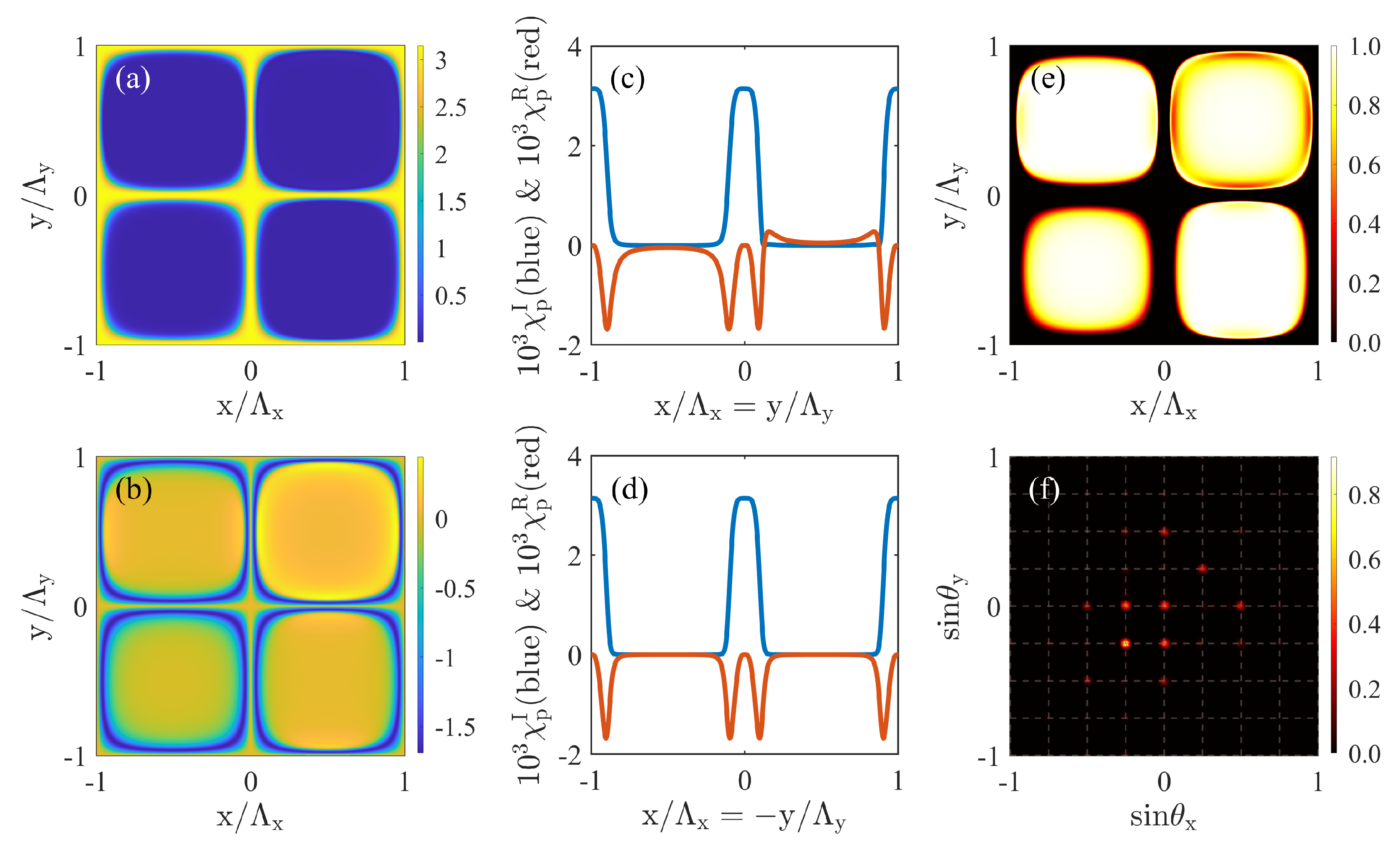
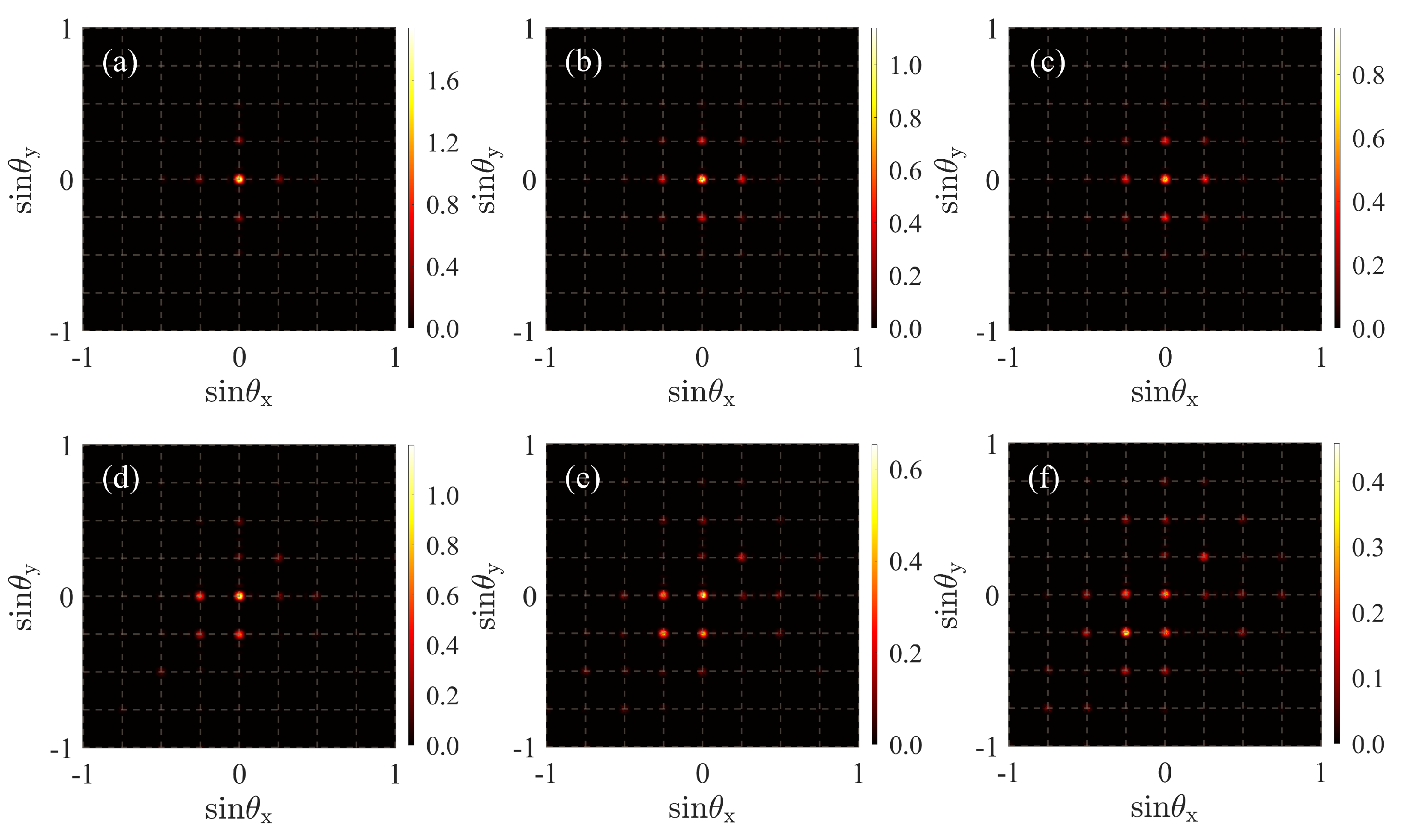
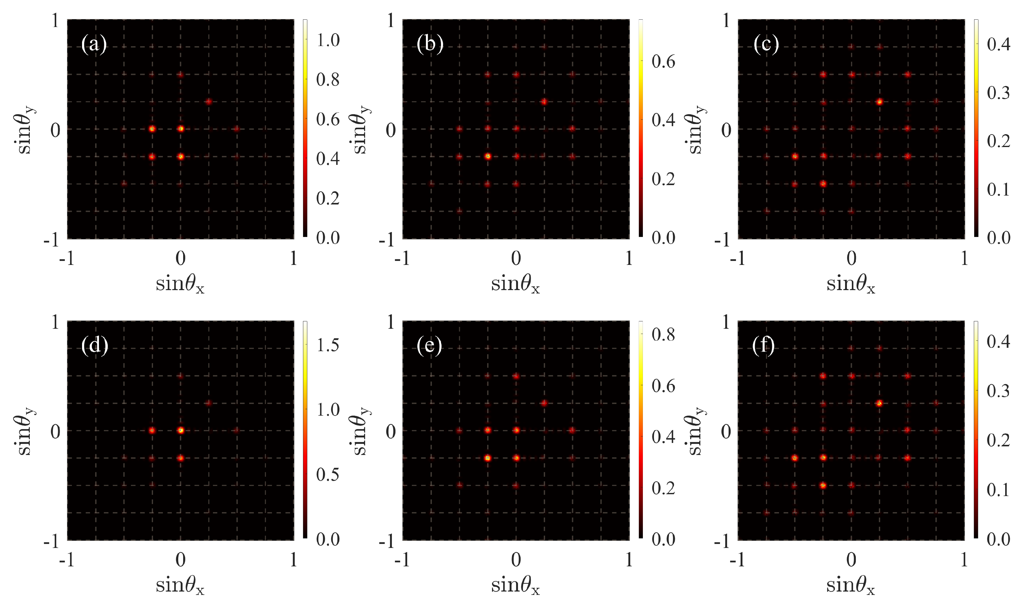
3. Results and Discussion

Discussions in the last section indicate that the realization of a controlled EIG requires a tunable probe susceptibility periodically modulated in space. With this consideration, we have plotted the 2D distributions of the probe susceptibility in the x y plane in Figure 2a,b and meanwhile shown corresponding values in the diagonal x = y and x = y directions in Figure 2c,d. It can be seen that the real and imaginary parts of the probe susceptibility are slightly asymmetric in the x = y direction but roughly symmetric in the x = y direction, indicating a visible out-of-phase interplay between the amplitude and phase modulations of the transmission function (cf. Equation (12)). This becomes possible only by including the Rydberg-induced level shift δ v d W in the case that Ω c and Δ c have been modulated with identical phases ( α x = β x and α y = β y ) and vanishing offsets ( Ω c 0 = Δ c 0 = 0 ). That is, Ω c and Δ c will exhibit different offsets if we replace Δ c 0 with Δ c 0 + δ v d W , which then results in the out-of-phase interplay between the amplitude and phase modulations of the transmission function. This is why asymmetric intensity distributions have been observed in Figure 2e,f with respect to the transmission and diffraction of the probe field, respectively. Keep in mind that δ v d W is not a constant in space since it is proportional to ρ r r depending on both Ω c and Δ c .
To further examine the effects of v d W interactions on a 2D Rydberg EIG, we have plotted in Figure 3 the far-field diffraction patterns in the absence ( δ Δ c = 0 ) and presence ( δ Δ c 0 ) of a spatially periodic modulation of detuning Δ c . We find that symmetric diffraction patterns appear in Figure 3a–c, which is not of surprise because only Ω c is periodically modulated in the x y plane. We observe, however, asymmetric diffraction patterns in Figure 3d–f, which is not straightforward to understand because Ω c and Δ c exhibit in-phase spatial modulations with Ω c 0 = Δ c 0 = 0 , α x = β x , and α y = β y . This should be attributed to the fact that a notable Rydberg shift δ v d W must be added to detuning Δ c , hence leading to an out-of-phase interplay between the spatial modulations of Ω c and Δ c . We find in particular that the intensity distribution is shifted from lower to higher diffraction orders as the atomic density N 0 increases in an appropriate range. This embodies also an important effect of δ v d W because it is proportional to N 0 2 , as can be seen from Equation (4). Alternatively, one can increase Δ c 0 in the case of Ω c 0 = 0 to strengthen the out-of-phase interplay of Ω c and Δ c and hence shift the intensity distribution from lower- to higher-order diffraction patterns.
Next, we examine what will happen to the far-field 2D diffraction pattern as the modulation amplitude δ Δ c or the sample length L varies in an appropriate range. We can see from Figure 4a–c that increasing δ Δ c from 1.5 Γ e g to 4.5 Γ e g will result in an evident shift from lower toward higher diffraction orders and meanwhile a notable reduction in diffraction peak intensities. The underlying physics may be that a stronger modulation of Δ c is beneficial to attain a more prominent out-of-phase interplay between it and a fixed modulation of Ω c , yet inevitably leading to weaker atom–light interactions featured by a larger mean value of Δ c . Similar asymmetric behaviors with respect to the far-field diffraction pattern can be found from Figure 4d–f, where higher diffraction orders become more and more evident as the sample length L changes from 100 z 0 to 400 z 0 , which was attainable in recent experiments [44,45,46] and allows one to observe obvious diffraction effects. This is due, however, to the fact that a longer atom–light interaction path helps to transfer diffracted photons from lower orders to higher orders and meanwhile results in more accumulated losses for diffracted photons. It is worth noting that these newly appearing higher diffraction orders are always located in the upper right part (i.e., cannot be shifted to the other three parts) in the x y plane as Δ c 0 , δ Δ c , L, and N 0 are varied to control the 2D diffraction pattern.
Finally, we examine what will happen to the far-field 2D diffraction pattern with a more direct method for controlling the out-of-phase interplay between Ω c and Δ c . This is shown in Figure 5, where initial phases α x and α y with respect to Ω c are fixed while β x and β y with respect to Δ c are varied. It is easy to see that only four diffraction orders can be observed in a single quadrant, leaving the other three quadrants empty in the x y plane. In addition, it is visible to shift the four diffraction orders to any quadrant on demand by choosing appropriate values of β x and β y . The underlying physics lies in the fact that the absorption ( χ p I ) and dispersion ( χ p R ) properties can be tuned to satisfy the PT anti-symmetry along different directions, as shown by the corresponding insets. Taking Figure 5a,c as an example, it is roughly true that the probe susceptibility is modulated in a PT anti-symmetric way along the x = y direction because χ p I ( x = y ) is an even function while χ p R ( x = y ) is an odd function to a good approximation. This is why the four diffraction orders appear in the first and third quadrants in Figure 5a,c, respectively. Similar conclusions hold for Figure 5b,d, where the probe susceptibility is modulated in a PT anti-symmetric way along the x = y direction instead, so that the four diffraction orders appear in the second and fourth quadrants, respectively. Note also that the relative strength of the four diffraction maxima in each panel has no direct relation with the dispersion distribution in a corresponding inset. That is, the strongest diffraction maximum may change from one order (e.g., the top left) to another order (e.g., the bottom right), while the dispersion distribution remains unchanged, as we increase or decrease the sample length L.

4. Conclusions

In summary, we have investigated a practicable scheme for realizing a 2D asymmetric EIG in a three-level ladder system of Rydberg atoms driven by a probe field and a control field. With 2D correlated modulations in the amplitude and frequency of the control field, we show that the probe field exhibits, in principle, an asymmetric diffraction pattern due to a Rydberg-induced level shift δ v d W added to detuning Δ c of the control field. It is found in particular that one can shift the intensity distribution from lower toward higher diffraction orders along a certain direction, e.g., by increasing modulation offset Δ c 0 , modulation amplitude δ Δ c , atomic density N 0 , and sample length L, thus yielding enhanced higher-order diffraction efficiencies. It is also possible to observe diffraction intensity distributions only in one quadrant in the x y plane and shift them to any desired quadrant by choosing appropriate modulation phases of the control field. Our scheme provides an opportunity for developing novel photonic devices involving asymmetric light transport, such as all-optical switches, routers, and optical imaging.

Author Contributions

Conceptualization, B.W., D.Y. and J.W.; methodology, B.W., Y.L. and J.W.; software, Y.L.; validation, D.Y.; formal analysis, B.W., D.Y. and J.W.; writing—original draft preparation, B.W.; writing—review and editing, J.W.; visualization, B.W.; project administration, J.W. All authors have read and agreed to the published version of the manuscript.

Funding

This work is supported by the National Natural Science Foundation of China (Grant No. 12074061).

Institutional Review Board Statement

Not applicable.

Informed Consent Statement

Not applicable.

Data Availability Statement

Not applicable.

Conflicts of Interest

The authors declare no conflict of interest.

References

  1. Fleischhauer, M.; Imamoglu, A.; Marangos, J.P. Electromagnetically induced transparency: Optics in coherent media. Rev. Mod. Phys. 2005, 77, 633–673. [Google Scholar] [CrossRef]
  2. Vanier, J.; Godone, A.; Levi, F. Coherent population trapping in cesium: Dark lines and coherent microwave emission. Phys. Rev. A 1998, 58, 2345–2358. [Google Scholar] [CrossRef]
  3. Harris, S.E. Lasers without inversion: Interference of lifetime-broadened resonances. Phys. Rev. Lett. 1989, 62, 1033–1036. [Google Scholar] [CrossRef] [PubMed]
  4. Harris, S.E.; Field, J.E.; Imamoğlu, A. Nonlinear optical processes using electromagnetically induced transparency. Phys. Rev. Lett. 1990, 64, 1107–1110. [Google Scholar] [CrossRef]
  5. Harris, S.E. Electromagnetically Induced Transparency. Phys. Today 1997, 50, 36–42. [Google Scholar] [CrossRef]
  6. Hau, L.V.; Harris, S.E.; Dutton, Z.; Behroozi, C.H. Light speed reduction to 17 metres per second in an ultracold atomic gas. Nature 1999, 397, 594–598. [Google Scholar] [CrossRef]
  7. Kash, M.M.; Sautenkov, V.A.; Zibrov, A.S.; Hollberg, L.; Welch, G.R.; Lukin, M.D.; Rostovtsev, Y.; Fry, E.S.; Scully, M.O. Ultraslow Group Velocity and Enhanced Nonlinear Optical Effects in a Coherently Driven Hot Atomic Gas. Phys. Rev. Lett. 1999, 82, 5229–5232. [Google Scholar] [CrossRef]
  8. Liu, C.; Dutton, Z.; Behroozi, C.H.; Hau, L.V. Observation of coherent optical information storage in an atomic medium using halted light pulses. Nature 2001, 409, 490–493. [Google Scholar] [CrossRef]
  9. Longdell, J.J.; Fraval, E.; Sellars, M.J.; Manson, N.B. Stopped Light with Storage Times Greater than One Second Using Electromagnetically Induced Transparency in a Solid. Phys. Rev. Lett. 2005, 95, 063601. [Google Scholar] [CrossRef]
  10. Harris, S.E.; Yamamoto, Y. Photon Switching by Quantum Interference. Phys. Rev. Lett. 1998, 81, 3611–3614. [Google Scholar] [CrossRef] [Green Version]
  11. Yan, M.; Rickey, E.G.; Zhu, Y. Nonlinear absorption by quantum interference in cold atoms. Opt. Lett. 2001, 26, 548–550. [Google Scholar] [CrossRef] [PubMed]
  12. Lukin, M.D.; Imamoğlu, A. Nonlinear Optics and Quantum Entanglement of Ultraslow Single Photons. Phys. Rev. Lett. 2000, 84, 1419–1422. [Google Scholar] [CrossRef] [PubMed]
  13. Lukin, M.D.; Imamoğlu, A. Controlling photons using electromagnetically induced transparency. Nature 2001, 413, 273–276. [Google Scholar] [CrossRef]
  14. Ling, H.Y.; Li, Y.Q.; Xiao, M. Electromagnetically induced grating: Homogeneously broadened medium. Phys. Rev. A 1998, 57, 1338–1344. [Google Scholar] [CrossRef]
  15. Mitsunaga, M.; Imoto, N. Observation of an electromagnetically induced grating in cold sodium atoms. Phys. Rev. A 1999, 59, 4773–4776. [Google Scholar] [CrossRef]
  16. de Araujo, L.E.E. Electromagnetically induced phase grating. Opt. Lett. 2010, 35, 977–979. [Google Scholar] [CrossRef]
  17. Carvalho, S.A.; de Araujo, L.E.E. Electromagnetically induced blazed grating at low light levels. Phys. Rev. A 2011, 83, 053825. [Google Scholar] [CrossRef]
  18. Liu, Y.M.; Gao, F.; Fan, C.H.; Wu, J.H. Asymmetric light diffraction of an atomic grating with PT symmetry. Opt. Lett. 2017, 42, 4283–4286. [Google Scholar] [CrossRef]
  19. Hang, C.; Li, W.; Huang, G. Nonlinear light diffraction by electromagnetically induced gratings with PT symmetry in a Rydberg atomic gas. Phys. Rev. A 2019, 100, 043807. [Google Scholar] [CrossRef]
  20. Zhou, F.; Qi, Y.; Sun, H.; Chen, D.; Yang, J.; Niu, Y.; Gong, S. Electromagnetically induced grating in asymmetric quantum wells via Fano interference. Opt. Express 2013, 21, 12249–12259. [Google Scholar] [CrossRef]
  21. Tian, S.C.; Wan, R.G.; Wang, L.J.; Shu, S.L.; Lu, H.Y.; Zhang, X.; Tong, C.Z.; Feng, J.L.; Xiao, M.; Wang, L.J. Asymmetric light diffraction of two-dimensional electromagnetically induced grating with PT symmetry in asymmetric double quantum wells. Opt. Express 2018, 26, 32918–32930. [Google Scholar] [CrossRef] [PubMed]
  22. Naseri, T. Electromagnetically induced grating with second field quantization in spherical semiconductor quantum dots. Opt. Quantum Electron. 2020, 52, 252. [Google Scholar] [CrossRef]
  23. Naseri, T. Optical properties and electromagnetically induced grating in a hybrid semiconductor quantum dot-metallic nanorod system. Phys. Lett. A 2020, 384, 126164. [Google Scholar] [CrossRef]
  24. Liu, Y.M.; Gao, F.; Wu, J.H.; Artoni, M.; La Rocca, G.C. Lopsided diffractions of distinct symmetries in two-dimensional non-Hermitian optical gratings. Phys. Rev. A 2019, 100, 043801. [Google Scholar] [CrossRef]
  25. Ma, D.; Yu, D.; Zhao, X.D.; Qian, J. Unidirectional and controllable higher-order diffraction by a Rydberg electromagnetically induced grating. Phys. Rev. A 2019, 99, 033826. [Google Scholar] [CrossRef]
  26. Wu, J.H.; Artoni, M.; La Rocca, G.C. Non-Hermitian Degeneracies and Unidirectional Reflectionless Atomic Lattices. Phys. Rev. Lett. 2014, 113, 123004. [Google Scholar] [CrossRef]
  27. Zhang, Z.; Zhang, Y.; Sheng, J.; Yang, L.; Miri, M.A.; Christodoulides, D.N.; He, B.; Zhang, Y.; Xiao, M. Observation of Parity-Time Symmetry in Optically Induced Atomic Lattices. Phys. Rev. Lett. 2016, 117, 123601. [Google Scholar] [CrossRef]
  28. Peng, P.; Cao, W.; Shen, C.; Qu, W.; Wen, J.; Jiang, L.; Xiao, Y. Anti-parity–time symmetry with flying atoms. Nat. Phys. 2016, 12, 1139–1145. [Google Scholar] [CrossRef]
  29. Lu, X.; Chen, N.; Zhang, B.; Yang, H.; Chen, Y.; Zhang, X.; Xu, J. Parity-Time Symmetry Enabled Band-Pass Filter Featuring High Bandwidth-Tunable Contrast Ratio. Photonics 2022, 9, 380. [Google Scholar] [CrossRef]
  30. Wang, L.; Zhou, F.; Hu, P.; Niu, Y.; Gong, S. Two-dimensional electromagnetically induced cross-grating in a four-level tripod-type atomic system. J. Phys. B At. Mol. Opt. Phys. 2014, 47, 225501. [Google Scholar] [CrossRef]
  31. Wu, J.C.; Hu, T.T. Two-dimensional electromagnetically induced gain-phase grating with an incoherent pump field. Laser Phys. Lett. 2018, 15, 065202. [Google Scholar] [CrossRef]
  32. Naseri, T. Two-dimensional induced grating in Rydberg atoms via microwave field. Eur. Phys. J. Plus 2019, 134, 530. [Google Scholar] [CrossRef]
  33. Asghar, S.; Ziauddin; Qamar, S.; Qamar, S. Electromagnetically induced grating with Rydberg atoms. Phys. Rev. A 2016, 94, 033823. [Google Scholar] [CrossRef]
  34. Liu, Y.M.; Tian, X.D.; Wang, X.; Yan, D.; Wu, J.H. Cooperative nonlinear grating sensitive to light intensity and photon correlation. Opt. Lett. 2016, 41, 408–411. [Google Scholar] [CrossRef]
  35. Gallagher, T.F. Rydberg Atoms; Cambridge Monographs on Atomic, Molecular and Chemical Physics, Cambridge University Press: Cambridge, UK, 1994. [Google Scholar] [CrossRef]
  36. Šibalić, N.; Adams, C.S. Rydberg Physics; IOP Publishing: London, UK, 2018; pp. 2399–2891. [Google Scholar] [CrossRef]
  37. Yan, D.; Bai, W.; Bai, J.; Chen, L.; Han, H.; Wu, J. Dynamical Collective Excitations and Entanglement of Two Strongly Correlated Rydberg Superatoms. Photonics 2022, 9, 242. [Google Scholar] [CrossRef]
  38. DeSalvo, B.J.; Aman, J.A.; Gaul, C.; Pohl, T.; Yoshida, S.; Burgdörfer, J.; Hazzard, K.R.A.; Dunning, F.B.; Killian, T.C. Rydberg-blockade effects in Autler-Townes spectra of ultracold strontium. Phys. Rev. A 2016, 93, 022709. [Google Scholar] [CrossRef]
  39. Han, J.; Vogt, T.; Li, W. Spectral shift and dephasing of electromagnetically induced transparency in an interacting Rydberg gas. Phys. Rev. A 2016, 94, 043806. [Google Scholar] [CrossRef]
  40. Weimer, H.; Löw, R.; Pfau, T.; Büchler, H.P. Quantum Critical Behavior in Strongly Interacting Rydberg Gases. Phys. Rev. Lett. 2008, 101, 250601. [Google Scholar] [CrossRef] [Green Version]
  41. Steck, D.A. Rubidium 87 D Line Data. Website. 2021. Available online: http://steck.us/alkalidata (accessed on 9 July 2021).
  42. Singer, K.; Stanojevic, J.; Weidemüller, M.; Côté, R. Long-range interactions between alkali Rydberg atom pairs correlated to the ns-ns, np-np and nd-nd asymptotes. J. Phys. B At. Mol. Opt. Phys. 2005, 38, S295–S307. [Google Scholar] [CrossRef]
  43. Zhang, H.; Yuan, J.; Dong, S.; Wu, C.; Wang, L. Observation of an Electromagnetically Induced Grating in Cold 85Rb Atoms. Appl. Sci. 2020, 10, 5740. [Google Scholar] [CrossRef]
  44. Gorniaczyk, H.; Tresp, C.; Bienias, P.; Paris-Mandoki, A.; Li, W.; Mirgorodskiy, I.; Büchler, H.P.; Lesanovsky, I.; Hofferberth, S. Enhancement of Rydberg-mediated single-photon nonlinearities by electrically tuned Förster resonances. Nat. Commun. 2016, 7, 12480. [Google Scholar] [CrossRef] [PubMed]
  45. Pritchard, J.D.; Maxwell, D.; Gauguet, A.; Weatherill, K.J.; Jones, M.P.A.; Adams, C.S. Cooperative Atom-Light Interaction in a Blockaded Rydberg Ensemble. Phys. Rev. Lett. 2010, 105, 193603. [Google Scholar] [CrossRef] [PubMed]
  46. Liao, K.Y.; Tu, H.T.; Yang, S.Z.; Chen, C.J.; Liu, X.H.; Liang, J.; Zhang, X.D.; Yan, H.; Zhu, S.L. Microwave electrometry via electromagnetically induced absorption in cold Rydberg atoms. Phys. Rev. A 2020, 101, 053432. [Google Scholar] [CrossRef]
Figure 1. (a) Schematic of a 2D EIG realized with an ensemble of Rydberg atoms. The SW control field is applied along both x and y directions while the probe field is incident only along the z direction. (b) Schematic of a three-level ladder system of Rydberg atoms driven by a probe field Ω p on the lower transition and a control field Ω c on the upper transition. The three atomic states may refer, e.g., to | g | 5 S 1 / 2 , F = 2 , m F = 2 , | e | 5 S 1 / 2 , F = 3 , m F = 3 , and | r | 74 S 1 / 2 of the 87 Rb isotope.
Photonics 09 00674 g001
Figure 2. (a) Imaginary ( 10 3 χ p I ) and (b) real ( 10 3 χ p R ) parts of the probe susceptibility plotted against positions x and y together with their projections along the (c) x = y and (d) x = y directions. (e) Modulus | T | of the transmission coefficient plotted against positions x and y. (f) Fraunhofer diffraction intensity 10 I p plotted against sine functions of angles θ x and θ y . Relevant parameters are Γ e g / 2 π = 6.1 MHz, Γ r e / 2 π = 2.0 kHz, Ω c 0 = Δ c 0 = Δ p = 0 , δ Δ c = 2.0 Γ e g , Ω p = 0.15 Γ e g , δ Ω c = 12.5 Γ e g , α x = α y = 0 , β x = β y = 0 , λ p = 0.795 μ m, C 6 / 2 π = 1.65 THz · μ m 6 , N 0 = 5.18 × 10 10 cm 3 , L = 200 z 0 , z 0 = 5.35 μ m, M x = M y = 5 , and R x = R y = 4 [21,24,25,34,41,42,43].
Photonics 09 00674 g002
Figure 3. Fraunhofer diffraction intensity 10 I p plotted against sine functions of angles θ x and θ y . The upper panels are attained for δ Δ c = 0 with (a) Δ c 0 = 0 and N 0 = 2.5 × 10 10 cm 3 ; (b) Δ c 0 = Γ e g and N 0 = 2.5 × 10 10 cm 3 ; (c) Δ c 0 = Γ e g and N 0 = 4.0 × 10 10 cm 3 . The lower panels are attained for Δ c 0 = 0 and δ Δ c = 2.0 Γ e g with (d) N 0 = 1.0 × 10 10 cm 3 ; (e) N 0 = 2.5 × 10 10 cm 3 ; (f) N 0 = 4.0 × 10 10 cm 3 . Other parameters are the same as in Figure 2.
Photonics 09 00674 g003
Figure 4. Fraunhofer diffraction intensity 10 I p plotted against sine functions of angles θ x and θ y . The upper panels are attained for L = 200 z 0 with (a) δ Δ c = 1.5 Γ e g ; (b) δ Δ c = 3.0 Γ e g ; (c) δ Δ c = 4.5 Γ e g . The lower panels are attained for δ Δ c = 2.0 Γ e g with (d) L = 100 z 0 ; (e) L = 200 z 0 ; (f) L = 400 z 0 . Other parameters are the same as in Figure 2.
Photonics 09 00674 g004
Figure 5. Same as Figure 2f except α x = π / 2 and α y = π / 2 , as well as (a) β x = 0 and β y = 0 ; (b) β x = 0 and β y = π ; (c) β x = π and β y = π ; (d) β x = π and β y = 0 . The insets show corresponding absorption (left) and dispersion (right) distributions plotted as χ p I ( x , y ) and χ p R ( x , y ) , respectively.
Photonics 09 00674 g005
Publisher’s Note: MDPI stays neutral with regard to jurisdictional claims in published maps and institutional affiliations.

