Communication

Experimental Proof-of-Concept of a Spatial Photonic Switch Based on an Off-Axis Zone Plate in Millimeter Wavelength Range

1
Rzhanov Institute of Semiconductor Physics, Siberian Branch of the Russian Academy of Sciences, 630090 Novosibirsk, Russia
2
General Physics Department, Novosibirsk State Technical University, 630073 Novosibirsk, Russia
3
General Physics Department, Novosibirsk State University, 630090 Novosibirsk, Russia
4
Nondestructive School, National Research Tomsk Polytechnic University, 634050 Tomsk, Russia
5
V.E. Zuev Institute of Atmospheric Optics, Siberian Branch of the Russian Academy of Sciences, 634021 Tomsk, Russia
*
Author to whom correspondence should be addressed.
Photonics 2022, 9(10), 670; https://doi.org/10.3390/photonics9100670
Submission received: 29 August 2022 / Revised: 14 September 2022 / Accepted: 15 September 2022 / Published: 20 September 2022
(This article belongs to the Special Issue Optical Wireless Communications and Applications)

Abstract

:
Optical switches are key elements in modern network communications. We present the results of the experimental verification of a new theoretical concept proposed earlier for a full-optical wavelength-selective dual-channel switch based on the photonic hook effect, which is free from using any micro-mechanical devices or nonlinear materials. A large-scale laboratory prototype of such a device based on an off-axis Wood zone plate is considered, and its main parameters in the millimeter wavelength range are investigated. On the basis of the experiments, we show that the optical isolation of switched channels for a switch based on an off-axis zone plate can achieve 15 dB at a frequency difference of 25 GHz in a frequency range of 93 to 136 GHz. Given the scaling, these results can be transferred to another range, including the optical one.

1. Introduction

The significant growth of data communications and the rapid development of dense wavelength-division multiplexing (DWDM) technology are creating the need for more robust and flexible signal management capabilities. In particular, the ability to optimize, route, and communicate data using optical methods is becoming critical. Optical switches are used in modern optical network communications [1], particularly to separate optical signals with different frequencies propagating over a single optical channel. To date, various types of microphotonic switching devices are elaborated and reported in the literature, e.g., interferometric switching cells based on a sub-wavelength optical grating [2], Micro Electro-Mechanical Systems (MEMS) switching matrices [3], mode interference-controlled electro-optical switches [4], semiconductor-based III–V CMOS switches [5], optical amplifier switching matrices [6], liquid crystal-based switches [7], and all-optical switches based on photonic crystal nanocavities [8].
Modern requirements for device microminiaturization dictate the need for developing the optical components and “systems-on-chip” because fast real-time reconfiguration using integrated optical circuit technologies will ensure energy-efficient and transparent data transmission and switching at high speed (in contrast to switching circuits based on electronics, which require control of an external electrical signal) [9]. Optical switches are also widely used for “neuromorphic” optical computing, simulating brain functions to parallel information processing and storage [10].
Different principles of optical switch designs are known nowadays [1,9,11,12,13,14,15]. The most common are the switches based on mirrors or lenses, which mechanically rotate or change their configuration to provide optical switching [16,17,18,19]. The main drawback of these switches is their rather low speed. Another class of switches includes wavelength-selective switches [20,21,22,23], which have attracted much attention because of their ability to independently route channels with different wavelengths. These are better suited for the modern photonic networks which must perform multiplexing and routing using only optical technologies based on the properties of optical radiation with different wavelengths.
Also worth mentioning is the family of wavelength-division multiplexing (WDM) multiplexers based on the generation of whispering gallery modes in transparent microspheres [24,25].
The physical principle underlying the previously proposed concept of non-contact spectrally selective switching of optical channels [26,27] is based on the effect of a curvilinear photonic flux generation during the propagation of an optical wave through a specific diffractive optical element with wavelength-scale dimensions. This class of devices belongs to the family of wavelength-selective switches [1,9]. In principle, the creation of a curvilinear photonic flux (a photonic hook) can be achieved in several ways. One way is to use an optically homogeneous particle, but having an asymmetry of geometric shape or using the asymmetry of the illuminating beam. For example, it can be a rectangular prism, a cylinder [28,29] or an ellipsoid under side illumination [30], an asymmetric planar lens in the form of a mesoscale off-axis phase plate [31], etc. Another method of producing a curved photonic flux exploits the geometrically symmetrical wavelength-scaled particles, but having a specially created asymmetry of the refractive index [28]. These are the so-called Janus particles obtained by combining two or more materials with different optical properties [32].
An important feature of a photonic hook which enables the realization the function of an optical switch is the dependence of the curvature of the produced photonic jet on the optical wavelength. Therefore, with a certain spatial configuration of the photonic switch and properly chosen receiving angles, it is possible to achieve a change in the optical signals in each switching channel as the radiation wavelength changes, without using mechanical scanning systems or nonlinear material properties.
In this communication, we present the results of the experimental proof of the concept of the above-mentioned optical switch in the millimeter (MM) wavelength range, fabricated as a scaled-up version of the optical switch due to the linearity of Maxwell’s equations. To realize the optical switching function, the required dependence of the curvature angle of the focused radiation on the irradiation wavelength is provided by a diffractive element in the form of a zone plate. Specifically, the spatial tilt of the near-field focusing region is provided using an off-axis Wood zone plate (WZP) providing the focusing outside the optical axis of the system.

2. Materials and Methods

The scheme of the experimental setup, its main components, and its operation principle are shown in Figure 1 and Figure 2. MM radiation is generated by the source and passes through a waveguide to a Cassegrain antenna producing a quasi-planar electromagnetic wave with the diameter D ≈ 100 mm, which exposes the phase plate. The distance d from the Cassegrain antenna to the WZP is much greater than the working aperture of the antenna D, i.e., the far-field conditions are realized. After the WZP, the MM radiation is focused in the plane ZX, located outside the optical axis of the incident radiation. Depending on the radiation frequency, the beam focusing position is shifted along the Z-axis in the ZX plane. To measure the spatial distribution of the radiation intensity in the ZX plane, the photodetector is placed in the center of a two-coordinate motorized stage with the electromechanical drives controlled by the computer. Coordinate scanning of the focusing region is carried out by the photodetector within the area of 100 × 100 mm with the spatial step of 0.5 mm.
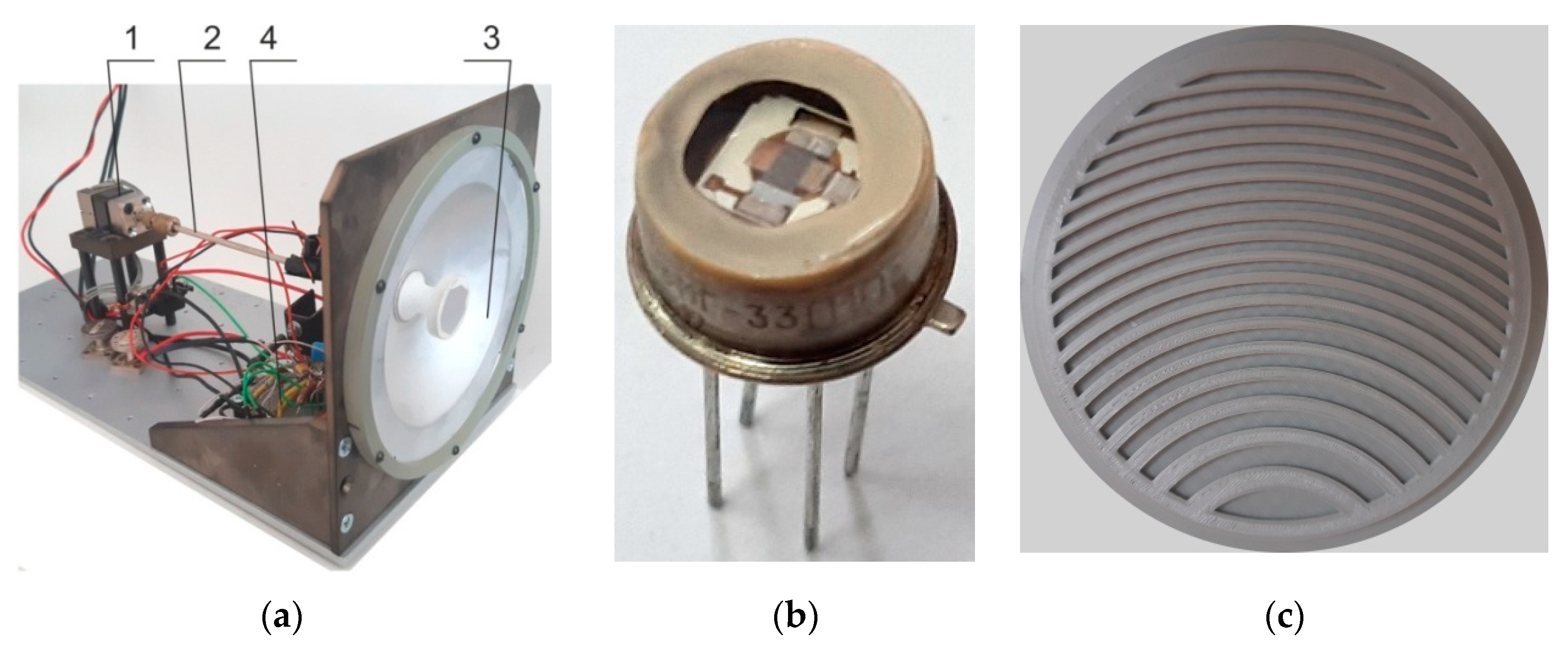
The radiation source (Figure 2a) is a monolithic Gann diode-based MM radiation module with operating frequencies of 93, 118 and 136 GHz (with frequency accuracy ±0.1 GHz and tuning range ±0.75 GHz) and output power of 3, 1 and 0.2 mW, respectively. The MM modules (1) are equipped with a waveguide (2) terminating in a Cassegrain antenna (3). An electronic circuit (4) is used to control the source. The antenna provides a quasi-planar wave front with a radiation beam divergence of less than 1°.
As an MM radiation sensor, the pyroelectric photodetector (see the appearance in Figure 2b) based on tetraaminodiphenyl with an extended range of spectral sensitivity (0.4–3000 µm) is used. The photodetector has an input window of polyethylene terephthalate with a diameter of 5 mm and a photosensitive pad with an area of 1 × 1 mm2. The characteristics of the used pyroelectric photodetector are studied in detail in [33,34]. To obtain the maximum signal from the pyroelectric detector, the MM radiation is modulated with a frequency of about 100 Hz using a mechanical obturator.
An asymmetric photonic structure in the form of an off-axis binary Wood phase plate [31,35] is used as an optical switching element, as shown in Figure 2c. The structure has the form of concentric circles with a given width and height formed on a common base. The radii of the binary plate are calculated by Formula (1):
ri = (iλF + (iλ/2)2)1/2,
where ri is the i-circle radius, λ is the wavelength, and F is the plate focus length.
The step height h in the plate structure was determined by Formula (2):
h = λ/(2(n − 1)),
where n is the refractive index of the plate material. The plate base thickness is 2 mm.
WZP with the diameter DW = 120 mm is fabricated by 3D printing [36] on a Cheap3d V300 printer with a printing area of 300 × 300 × 300 mm, with an accuracy of 50 μm. The material used is an ABS plastic REC rod with a diameter of 1.75 mm. Losses in this material are not significant for the given thicknesses and are determined mainly by Fresnel reflection. The refractive index of the material according to the data [37] is n ≈ 1.59 and can be slightly varied by choosing the density of 3D printing [38]. Note that at such geometrical parameters of the mesoscale WZP, the Mie-size parameter of the structure is q = π DW/λ = 31 π, which falls into the range of the photonic jet effect manifestation [39].
The measurement procedure is as follows (see Figure 1). The MM radiation source with a waveguide and a Cassegrain antenna (Figure 2a) and an off-axis Wood phase plate (Figure 2c) are mounted on a single optical rail so that the center of the Wood plate is on the optical axis of the MM source. Behind the plate, a two-coordinate motorized stage with a pyroelectric detector (Figure 2b) is installed horizontally at a certain height so that the radiation focus coincides with the photosensitive area of the pyrodetector installed in the stage center. Note that the vertical position of the stage is below the optical axis of the setup. The stage can move along the optical Z-axis and the orthogonal X-axis. After measurements at one frequency, the radiation source is changed by a second one, and the stage is moved so that the focused radiation again hits the detector in the stage center. The procedure is repeated for the third frequency.

3. Results

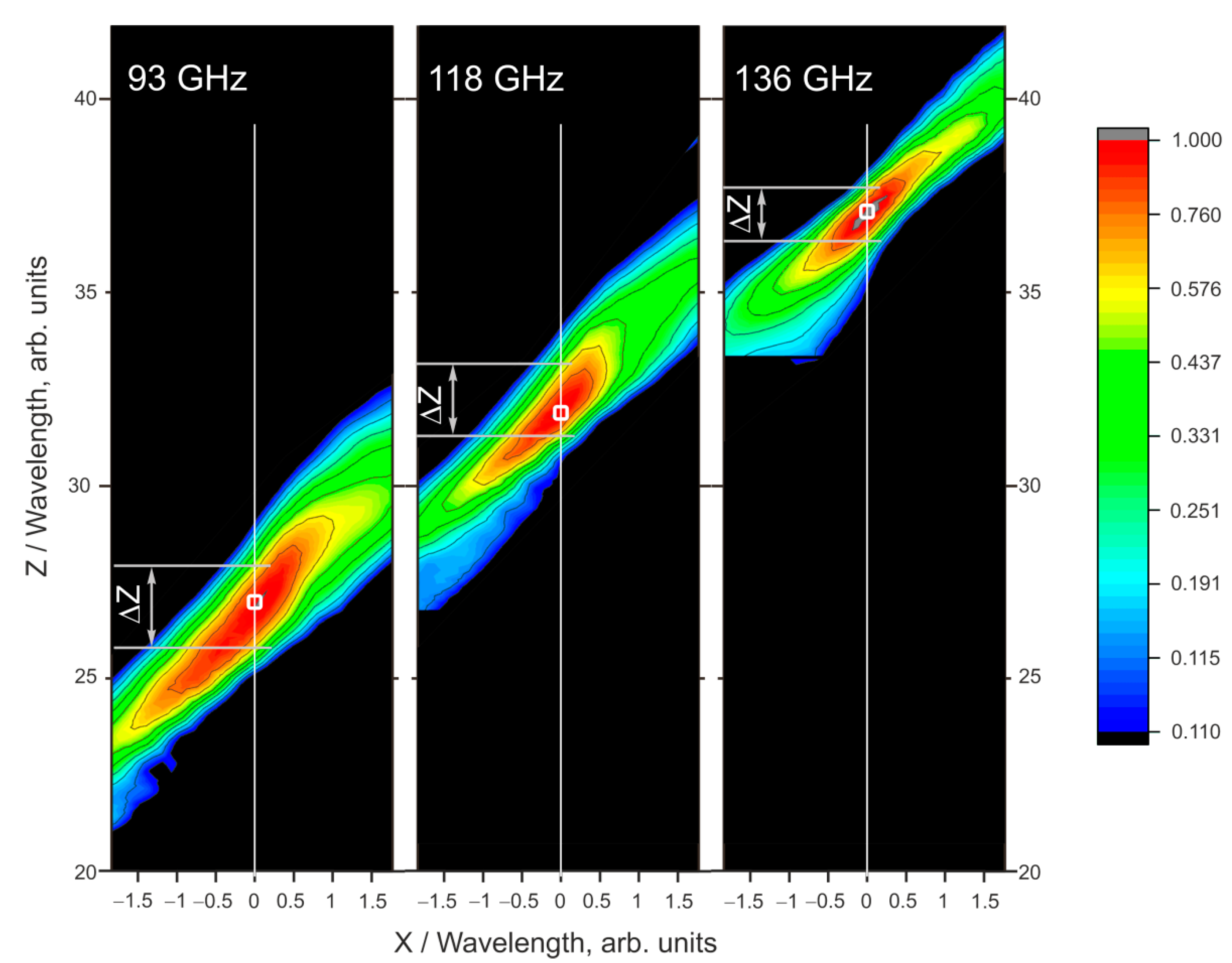
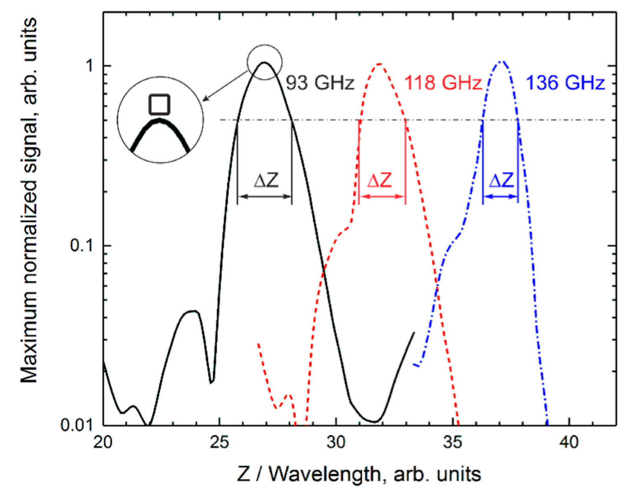
The results of the experiments are shown in Figure 3 and Figure 4, and Table 1. Figure 3 shows the two-dimensional distribution of MM wave intensity experiencing the diffraction on the WZP for three selected frequencies from 93 to 136 GHz. It can be seen from Figure 3 that when changing the frequency, the position of the focused radiation maximum shifts along the Z-axis by an amount exceeding the full width at half-maximum (FWHM) of the radiation intensity ZX-distribution (shown as ΔZ), thereby providing optical decoupling of the detectors. The dependence of MM radiation intensity along the optical Z-axis through the maxima at all frequencies (X = 0) is shown in Figure 4. In this figure, MM intensity is normalized to its maximal value obtained for each frequency, while Z coordinates are normalized to the radiation wavelength. The results of statistical processing of the obtained dependences are presented in Table 1. Figure 4 also shows the FWHMs (ΔZ) for each of the frequencies, and the size of the photosensitive area of the photodetector is shown in the inset as an open square. It can be seen that the size of the photosensitive area is significantly smaller than the characteristic intensity distribution region and allows it to be determined with sufficient accuracy.

4. Discussion

From these figures, it is seen that as expected, due to wave diffraction, the spatial size of the focusing region changes when the MM radiation propagates away from WZP. This is detailed in Table 1. Meanwhile, the electromagnetic wave localization region (off-axis focus [31,35]) changes its spatial position when the radiation wavelength changes. This is easy to understand, considering that for the peripheral zones of the off-axis Wood zone plate, their structure is described by a quasi-periodic law (see Figure 2c) following Formula (1). Therefore, the change in the diffraction angle is approximately described by the diffraction grating formula [40,41]. The placement of optical receivers along the Z-axis at X = 0 provides a different field amplitude in each of the switching channels when operating at different frequencies, enabling the spatial switching by the magnitude of the optical signal. Obviously, the operation reliability of such a switch depends on the value of optical decoupling of the channels, which in turn depends on the parameters of the switching phase plate and the irradiation wavelength range. The difference in electric signals from neighboring receivers, dS = S1S2, serves as a merit of the optical isolation (decoupling) of the switching channels. Note that to improve the optical decoupling of the switched channels, we chose a photodetector with an input aperture much smaller than the size of the cross-section of the radiation localization region (see Figure 4 Inset).
From Figure 4, one can see that the MM radiation intensity at the frequency 118 GHz, if measured at the coordinate of the signal maximum for 93 GHz, is more than 15 times lower than the maximal radiation intensity with a frequency of 93 GHz. In other words, the measured mutual influence of the intensity levels at adjacent frequencies is less than 15 dB.
Importantly, such a value of the radiation isolation dS of the switching routes (or crosstalk) is a satisfactory result, provided that the switch response speed is near instantaneous as, for example, the photodetectors based on Schottky diodes ZBD-F (Virginia Diodes, the response time is about 3 × 10⁻¹¹ s [42,43,44]). In this case, the spectral range of switching realization is about 43 GHz, about 38% of the average wavelength.
Given that the spectral and focusing properties of a zone plate are also valid for a planar design, the results obtained above, along with the areas of application mentioned in the introduction, can become the basis for integrated in-plane all-optical switches, for example, based on surface plasmon waves [45,46].

5. Conclusions

To conclude, we experimentally demonstrate the principal possibility of creating a multichannel (in this case, a three-channel) optical switch based on a dielectric mesoscale diffraction element with broken geometric symmetry in the form of an off-axis Wood zone plate. Due to the unique property of such a diffraction structure to change the spatial position of the diffraction-limited focusing region depending on the radiation wavelength, this switch is a suitable candidate for implementing electronic optical commutation in modern optoelectronics, one that does not require control of an electrical signal. It is worth noting that no full-scale optimization of the optical switch characteristics is intended in this work, and only the concept proposed earlier is experimentally demonstrated. Moreover, given the scalability of Maxwell’s equations [47], the results of this work can be transferred to other ranges of electromagnetic radiation, particularly to optical or infrared wavelength bands.

Author Contributions

Experiment preparation, A.G.P.; conceptualization, I.V.M. and O.V.M.; formal analysis, I.V.M., O.V.M. and A.G.P.; investigation, I.V.M., O.V.M. and A.G.P.; writing—original draft preparation, I.V.M. and O.V.M.; review and editing: A.G.P., I.V.M. and O.V.M.; translation, Y.E.G.; supervision, I.V.M. and O.V.M. All authors have read and agreed to the published version of the manuscript.

Funding

This research was funded by RFBR (no. 21-57-10001), Ministry of Science and Higher Education of the Russian Federation (V.E. Zuev Institute of Atmospheric Optics SB RAS).

Institutional Review Board Statement

Not applicable.

Informed Consent Statement

Not applicable.

Data Availability Statement

Not applicable.

Acknowledgments

This work was supported by the Tomsk Polytechnic University Development Program.

Conflicts of Interest

The authors declare no conflict of interest.

References

  1. El-Bawab, T.S. Optical Switching; Springer: Berlin/Heidelberg, Germany, 2006. [Google Scholar]
  2. Brunetti, G.; Marocco, G.; Di Benedetto, A.; Giorgio, A.; Armenise, M.N.; Ciminelli, C. Design of a large bandwidth 2 × 2 interferometric switching cell based on a sub-wavelength grating. J. Opt. 2021, 23, 085801. [Google Scholar] [CrossRef]
  3. Yeow, T.-W.; Law, K.L.E.; Goldenberg, A. MEMS optical switches. IEEE Commun. Mag. 2001, 39, 158–163. [Google Scholar] [CrossRef]
  4. Neyer, A. Electro-optic X-switch using single-mode Ti:LiNbO3 channel waveguides. Electron. Lett. 1983, 14, 553–554. [Google Scholar] [CrossRef]
  5. Ikku, Y.; Yokoyama, M.; Ichikawa, O.; Hata, M.; Takenaka, M.; Takagi, S. Low-driving-current InGaAsP photonic-wire optical switches using III-V CMOS photonics platform. Opt. Express 2012, 20, B357–B364. [Google Scholar] [CrossRef] [PubMed]
  6. Burmeister, E.F.; Mack, J.P.; Poulsen, H.N.; Klamkin, J.; Coldren, L.A.; Blumenthal, D.J.; Bowers, J.E. SOA gate array recirculating buffer for optical packet switching. In Proceedings of the Optical Fiber Communication Conference, San Diego, CA, USA, 24–28 February 2008; pp. 1–3. [Google Scholar] [CrossRef]
  7. D’Alessandro, A.; Asquini, R.; Menichella, F.; Ciminelli, C. Realisation and characterisation of a ferroelectric liquid crystal bistable optical switch. Mol. Cryst. Liq. Cryst. 2002, 372, 353–363. [Google Scholar] [CrossRef]
  8. Tanabe, T.; Notomi, M.; Mitsugi, S.; Shinya, A.; Kuramochi, E. All-optical switches on a silicon chip realized using photonic crystal nanocavities. Appl. Phys. Lett. 2005, 87, 151112. [Google Scholar] [CrossRef]
  9. Stabile, R.; Albores-Mejia, A.; Rohit, A.; Williams, K.A. Integrated optical switch matrices for packet data networks. Microsyst. Nanoeng. 2016, 2, 15042. [Google Scholar] [CrossRef]
  10. Cheng, Z.; Ríos, C.; Pernice, W.H.P.; Wright, C.D.; Bhaskaran, H. On-chip photonic synapse. Sci. Adv. 2017, 3, e1700160. [Google Scholar] [CrossRef]
  11. Cheng, Q.; Bahadori, M.; Glick, M.; Rumley, S.; Bergman, K. Recent advances in optical technologies for data centers: A review. Optica 2018, 5, 1354–1370. [Google Scholar] [CrossRef]
  12. Virgilio, M.; Witzigmann, B.; Bolognini, G.; Guha, S.; Schroeder, T.; Capellini, G. CMOS-compatible optical switching concept based on strain-induced refractive-index tuning. Opt. Express 2015, 23, 5930–5940. [Google Scholar] [CrossRef]
  13. Ravel, K.; Koechlin, C.; Prevost, E.; Bomer, T.; Poirier, R.; Tonck, L.; Guinde, G.; Beaumel, M.; Parsons, N.; Enrico, M.; et al. Optical switch matrix development for new concepts of photonic based flexible telecom payloads. In Proceedings of the SPIE 11180, International Conference on Space Optics—ICSO 2018, Chania, Greece, 9–12 October 2018; p. 111803H. [Google Scholar]
  14. Jia, H.; Yang, S.; Zhou, T.; Shao, S.; Fu, X.; Zhang, L.; Yang, L. WDM-compatible multimode optical switching system-on-chip. Nanophotonics 2019, 8, 889–898. [Google Scholar] [CrossRef]
  15. Williamson, I.A.D.; Fan, S. Broadband Optical Switch based on an Achromatic Photonic Gauge Potential in Dynamically Modulated Waveguides. Phys. Rev. Appl. 2019, 11, 054035. [Google Scholar] [CrossRef]
  16. Li, L.; Liu, C.; Peng, H.; Wang, Q. Optical switch based on electrowetting liquid lens. J. Appl. Phys. 2012, 111, 103103. [Google Scholar] [CrossRef]
  17. Seok, T.J.; Quack, N.; Han, S.; Muller, R.S.; Wu, M.C. Large-scale broadband digital silicon photonic switches with vertical adiabatic couplers. Optica 2016, 3, 64–70. [Google Scholar] [CrossRef]
  18. Han, S.; Seok, T.J.; Quack, N.; Yoo, B.-W.; Wu, M.C. Large-scale silicon photonic switches with movable directional couplers. Optica 2015, 2, 370–375. [Google Scholar] [CrossRef]
  19. Han, S.; Seok, T.J.; Yu, K.; Quack, N.; Muller, R.S.; Wu, M.C. Large-scale polarization-insensitive silicon photonic MEMS switches. J. Lightwave Technol. 2018, 36, 1824–1830. [Google Scholar] [CrossRef]
  20. Seok, T.J.; Luo, J.; Huang, Z.; Kwon, K.; Henriksson, J.; Jacobs, J.; Ochikubo, L.; Muller, R.S.; Wu, M.C. Silicon photonic wavelength cross-connect with integrated MEMS switching. APL Photonics 2019, 4, 100803. [Google Scholar] [CrossRef]
  21. Yamamoto, N.; Ogawa, T.; Komori, K. Photonic crystal directional coupler switch with small switching length and wide bandwidth. Opt. Express 2006, 14, 1223. [Google Scholar] [CrossRef]
  22. Strasser, T.A.; Wagener, J.L. Wavelength-selective switches for ROADM applications. IEEE J. Sel. Top. Quantum. Electron. 2010, 16, 1150–1157. [Google Scholar] [CrossRef]
  23. Zhang, C.; Zhang, M.; Xie, Y.; Shi, Y.; Kumar, R.; Panepucci, R.R.; Dai, D. Wavelength-selective 2 × 2 optical switch based on a Ge2Sb2Te5-assisted microring. Photon. Res. 2020, 8, 1171–1176. [Google Scholar] [CrossRef]
  24. Grujic, K.; Hole, J.P.; Hellesø, O.G.; Wilkinson, J.S. Whispering gallery modes excitation in borosilicate glass microspheres by K+ ion-exchanged channel waveguide coupler. In Proceedings of the SPIE: Photonics West: 8th International Conference on Laser Beam Control and Applications, San José, Costa Rica, 22–26 January 2006. [Google Scholar]
  25. Işçi, S.; Bilici, T.; Kurt, A.; Serpengüzel, A. Morphology-dependent resonances of optical microsphere resonators for the realization of passive wavelength-division multiplexing components. Opt. Eng. 2004, 43, 1051–1055. [Google Scholar] [CrossRef]
  26. Geints, Y.; Minin, O.V.; Yue, L.; Minin, I.V. Wavelength-scale photonic space switch proof-of-concept based on photonic hook effect. Ann. Phys. 2021, 533, 2100192. [Google Scholar] [CrossRef]
  27. Yue, L.; Wang, Z.; Xie, Y.; Geints, Y.; Minin, O.V.; Minin, I.V. Near-field light-bending photonic switch: Physics of switching based on three-dimensional Poynting vector analysis. Photonics 2022, 9, 154. [Google Scholar] [CrossRef]
  28. Geints, Y.; Minin, I.V.; Minin, O.V. Tailoring ‘photonic hook’ from Janus dielectric microbar. J. Opt. 2020, 22, 065606. [Google Scholar] [CrossRef]
  29. Minin, I.V.; Minin, O.V.; Liu, C.; Wei, H.; Geints, Y.; Karabchevsky, A. Experimental demonstration of a tunable photonic hook by a partially illuminated dielectric microcylinder. Opt. Lett. 2020, 45, 4899–4902. [Google Scholar] [CrossRef]
  30. Liu, C.; Chung, H.; Minin, O.V.; Minin, I.V. Shaping photonic hook via well-controlled illumination of finite-size graded-index micro-ellipsoid. J. Opt. 2020, 22, 085002. [Google Scholar] [CrossRef]
  31. Minin, I.V.; Minin, O.V.; Golodnikov, D.O. Simple free-space method for measurement of dielectric constant by means of diffractive optics with new capabilities. In Proceedings of the 8th International Conference on Actual Problems of Electronic Instrument Engineering, Novosibirsk, Russia, 26–28 September 2006; pp. 3–8. [Google Scholar]
  32. Su, H.; Hurd Price, H.; Jing, L.; Tian, Q.; Liu, J.; Qian, K. Janus particles: Design, preparation, and biomedical applications. Mater. Today Bio 2019, 4, 100033. [Google Scholar] [CrossRef]
  33. Paulish, A.G.; Gusachenko, A.V.; Morozov, A.O.; Dorozhkin, K.V.; Suslyaev, V.I.; Golyashov, V.A.; Minin, O.V.; Minin, I.V. Characterization of tetraaminediphenyl-based pyroelectric detector from visible to millimeter wave ranges. Opt. Eng. 2020, 59, 061612. [Google Scholar] [CrossRef]
  34. Paulish, A.G.; Gusachenko, A.V.; Morozov, A.O.; Golyashov, V.A.; Dorozhkin, K.V.; Suslyaev, V.I. Sensitivity of the tetraaminodiphenyl based pyroelectric sensor from visible to sub-THz range. Sens. Rev. 2020, 40, 291–296. [Google Scholar] [CrossRef]
  35. Guo, Y.J.; Barton, S.K. Offset Fresnel zone plate antennas. Int. J. Satell. Commun. 1994, 12, 381–385. [Google Scholar] [CrossRef]
  36. Monkevich, J.M.; Le Sage, G.P. Design and fabrication of a customdielectric Fresnel multi-zone plate lens antenna using additive manufacturing techniques. IEEE Access 2019, 7, 61452–61460. [Google Scholar] [CrossRef]
  37. Furlan, W.D.; Ferrando, V.; Monsoriu, J.A.; Zagrajek, P.; Czerwińska, E.; Szustakowski, M. 3D printed diffractive terahertz lenses. Opt. Lett. 2016, 41, 1748–1751. [Google Scholar] [CrossRef]
  38. Poyanco, J.M.; Pizarro, F.; Rajo-Iglesias, E. Cost-effective wideband dielectric planar lens antenna for millimeter wave applications. Sci. Rep. 2022, 12, 4204. [Google Scholar] [CrossRef] [PubMed]
  39. Minin, I.V.; Minin, O.V.; Lukianchuk, B.S. Mesotronic era of dielectric photonics. Proc. SPIE 2022, 12152, 89–93. [Google Scholar] [CrossRef]
  40. Born, M.; Wolf, E. Principles of Optics; Pergamon Press: New York, NY, USA, 1955. [Google Scholar]
  41. Pfeiffer, F.; David, C.; van der Veen, J.F.; Bergemann, C. Nanometer focusing properties of Fresnel zone plates described by dynamical diffraction theory. Phys. Rew. B 2006, 73, 245331. [Google Scholar] [CrossRef]
  42. Fast Detectors (ZBD-F). Available online: https://vadiodes.com/en/zbd (accessed on 12 August 2022).
  43. Zero-Bias Detector Operational Manual (ZBD, ZBD-F, QOD). Available online: https://www.amtechs.co.jp/product/ea0ce625ff6a2c70bbd3d4bdba61f36757498363.pdf (accessed on 12 August 2022).
  44. Park, C.H.; Lee, J.H. Formulas of 1/f noise in Schottky barrier diodes under reverse bias. Solid-State Electron. 2012, 69, 85–88. [Google Scholar] [CrossRef]
  45. Feng, L.; Tetz, K.; Slutsky, B.; Lomakin, V.; Fainman, V. Fourier plasmonics: Diffractive focusing of in-plane surface plasmon polariton waves. Appl. Phys. Lett. 2007, 91, 081101. [Google Scholar] [CrossRef]
  46. Podbiel, D.; Kahl, P.; Frank, B.; Davis, T.; Giessen, H.; Hoegen, M.; Heringdorf, F. patiotemporal Analysis of an Efficient Fresnel Grating Coupler for Focusing Surface Plasmon Polaritons. ACS Photonics 2019, 6, 600–604. [Google Scholar] [CrossRef]
  47. Vinogradov, A.P.; Aivazyan, A.V. Scaling theory for homogenization of the Maxwell equations. Phys. Rev. E 1999, 60, 987. [Google Scholar] [CrossRef]
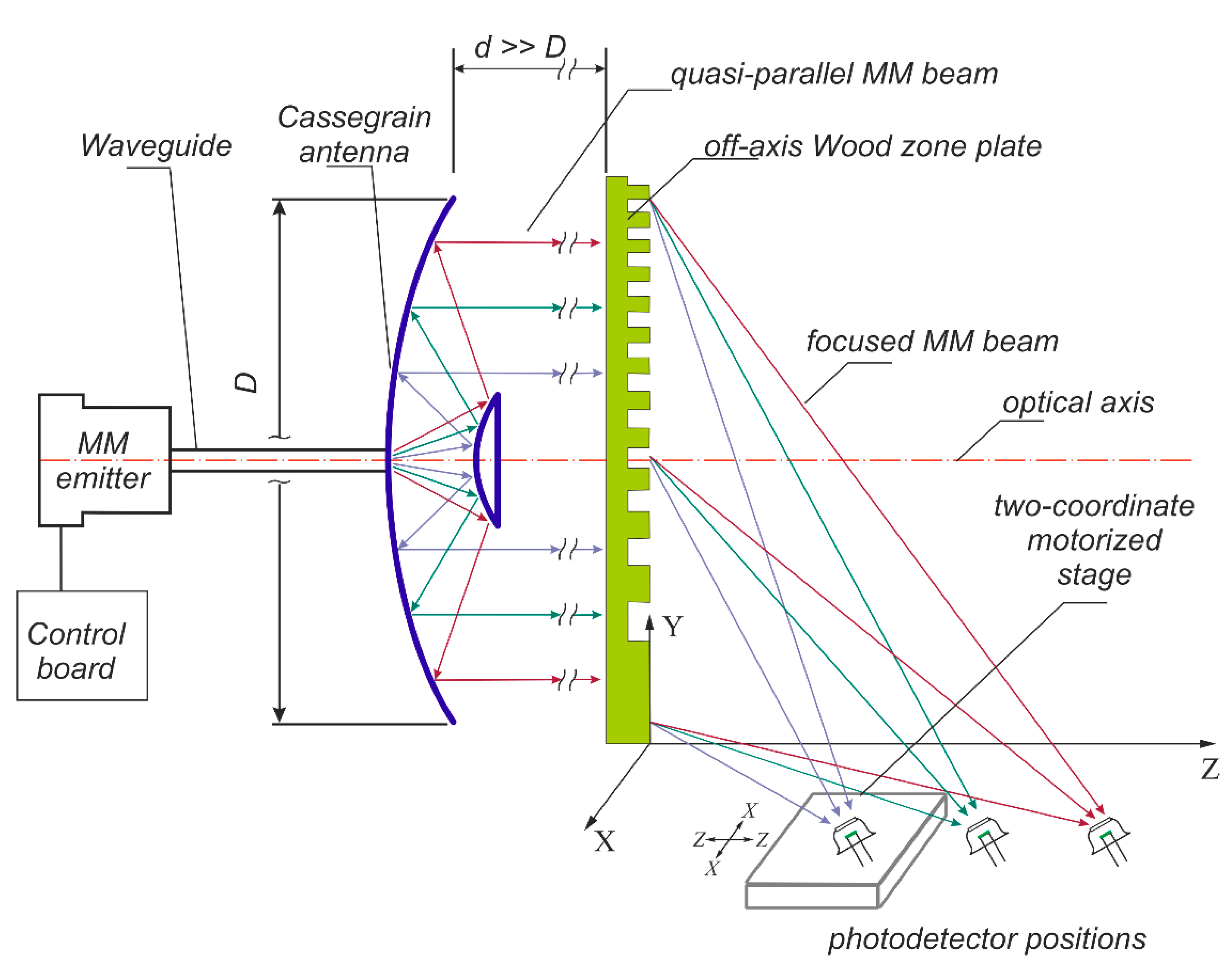
Figure 1. Experimental setup. The MM emitter, waveguide, Cassegrain antenna, and Wood zone plate are mounted on an optical rail (not shown) and on a single optical axis. The two-coordinate motorized stage with a pyroelectric detector in its center is installed horizontally so that the radiation focus coincides with the photosensitive area of the pyrodetector.
Photonics 09 00670 g001
Figure 2. (a) Appearance of MM radiation source, consisting of (1) MM emitter, (2) waveguide, (3) Cassegrain antenna, and (4) control board. (b) Pyroelectrical photodetector for the MM waveband. (c) Image of a Wood zone plate.
Photonics 09 00670 g002
Figure 3. MM intensity distribution in ZX plane at the frequencies 93 (left), 118 (middle), and 136 (right) GHz. X and Z coordinates are normalized to the radiation wavelength. Open squares show the boundaries of the photosensitive area of the pyroelectric receiver. The full width at half-maximum (FWHM) of intensity distribution along the Z-axis is shown as ΔZ.
Photonics 09 00670 g003
Figure 4. Dependence of MM radiation intensity along the optical Z-axis (shown in Figure 3 by a solid white line) at the frequencies 93, 118, and 136 GHz. The values are normalized to the maximum obtained for each frequency separately. The Z coordinate is normalized to the radiation wavelength. Inset: The photosensitive pad of the pyro-receiver (open square) shown in the scale of the figure data.
Photonics 09 00670 g004
Table 1. The parameters of MM radiation intensity Z-distribution for different switching channels.
Frequency (GHz)Wavelength (mm)Maximum Coordinate, Z/λ (arb. units)FWHM, ΔZ/λ (arb. units)FWHM, ΔZ/Z (%)
933.2326.92.298.5
1182.5431.81.865.8
1362.2137.11.564.2
Publisher’s Note: MDPI stays neutral with regard to jurisdictional claims in published maps and institutional affiliations.