1. Introduction
The generation of structured light fields is currently a hot and fast-growing topic in optical physics [
1,
2,
3,
4,
5]. Reconfigurable structured light fields with programmable spatio-temporal parameters are of increasing interest for numerous advanced applications such as ultrafast materials processing, plasma filament generation, optical communication, metrology, microscopy, information processing, particle tweezing, pulse characterization, or nonlinear spectroscopy. Recently, successful efforts were reported on beam shaping with digital mirror devices [
6,
7,
8,
9,
10,
11].
It is known that the imaging or shaping quality can be improved by implementing cascaded adaptive optical (AO) devices, e.g., as double-deformable-mirror systems for phase compensation in high-resolution microscopy, ophthalmoscopy, astronomy and other modern imaging techniques [
12,
13,
14,
15]. To overcome the limitations concerning the critical energy fluence on spatial light modulators (SLMs), which causes phase distortions or even material damage, power splitting by using multiple devices was demonstrated [
16]. Recently, it was shown that the combination of multi-aperture diffractive-optical elements and acousto-optic deflectors enables one to reach high temporal flexibility with repetition rates up to 330 kHz for conventional beam profiles and shaping on nanosecond scale [
17]. Such systems are of particular interest for high-speed and high-power micromachining.
To shape laser pulses at ultrashort pulse durations, however, efficient control of dispersion and diffraction is necessary. For appropriate diffraction management and beam smoothing, so-called apodization techniques can be applied [
18,
19,
20]. The essential mechanism of apodization consists of implementing soft apertures instead of apertures with hard edges in the optical systems. The term “apodization” is related to the resulting suppression of edge diffraction by appropriate window functions and stems from the Latin “apodisatio” meaning “eliminating foots” and goes even further back to a corresponding ancient Greek expression. In imaging optical systems, apodization by graded absorption or reflection layers [
21] or structured edges is often used to improve spatial resolution, e.g., for microscopes, telescopes [
22] or camera lenses. Diffraction limited imaging can be obtained by optimized diffractive lenses with apodization [
23]. Graded reflectance mirrors play an important role as spatially variable outcoupling mirrors and mode selectors in unstable laser resonators with large mode volumes [
24,
25]. Thus, the implementation of flexible, robust, and fast apodization techniques is a very attractive goal in modern optics, which profits from recent progress in the development of high-resolution pixelated commercial spatial light modulators.
DMDs are purely reflective devices that in most cases solve the problems of amplitude and phase steering by temporal accumulation of switching cycles and exploiting angular spectra of encoded diffractive gratings, respectively. The obtainable efficiencies are relatively low (typically between 1% and 20%). Although spectrally stable performance has been demonstrated with DMDs over a range of about 200 nm [
26], the angular shaping principle causes unwanted spatio-temporal coupling phenomena at extremely short pulse durations.
An alternative approach consists in the direct small-angle phase shaping with new types of fast steerable, highly reflective micro-electro-mechanical systems (MEMS) that enable large phase elongations and high-power structured beam generation at pulse durations down to the few-cycle range. Both the well-established beam shaper concepts based on DMDs or low-dispersion phase-only liquid-crystal-on-silicon spatial light modulators (LCoS-SLMs) [
27,
28,
29,
30,
31,
32] and the shape-variant MEMS with piezo- or thermal actuation [
33,
34,
35,
36,
37,
38,
39] exhibit specific advantages and drawbacks. Their combination, however, can be used to significantly improve system performance at ultrashort pulse durations and even to obtain new functionality.
In the following, explorative studies of selected configurations on the basis of liquid crystal devices working at small deflecting angles are reported. These systems integrate (i) the structural flexibility and adaptive capability of high-resolution, pixelated LCoS-SLMs with (ii) the high obtainable phase-stroke, faster possible switching speed and the low dispersion of reflective MEMS or electrically tunable fluid lenses. Specific advantages and disadvantages of this particular type of combined system will be discussed, and applications for low-distortion shaping and characterization of ultrashort wavepackets will be proposed. Tunable nondiffracting self-imaging will be presented here for the first time, to the best of our knowledge.
2. Self-Apodization and “Doubly Nondiffracting” Beams
The approach of combined systems enables one to realize specific unconventional scenarios of nondiffracting beam shaping and apodization. The intensity profile of the beam shaped by a first active component (e.g., LCoS-SLM) illuminating the second active component (e.g., MEMS) acts as a spatial filter function. In comparison to other approaches, this one is relatively simple and highly flexible at the same time.
Depending on the application, different design criteria can be considered. In particular, this can be (a) the beam diameter (e.g., to completely illuminate the active area of a spatial light modulator for simultaneously shaping a maximum number of partial beams as an array with maximum possible sampling resolution), (b) the smoothness of the illuminating beam (to minimize diffraction and to avoid hot spots), and (c) the final beam divergence.
This approach enables the generation of nondiffracting (ND) Bessel-like beams [
40] or light bullets [
41,
42]; light slices; or even more complex structured wavepackets [
41,
43] under the conditions of so-called “self-apodization” [
44,
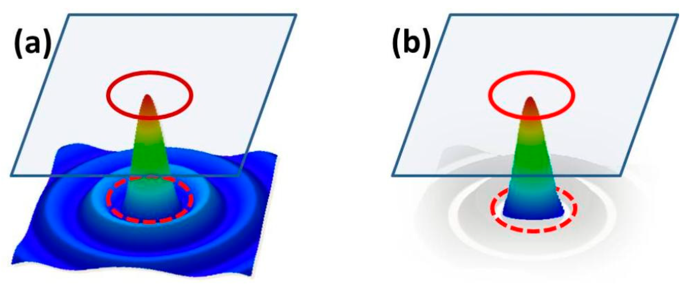
45], i.e., with apodization at an optimum coincidence of spatial intensity zeros (or minima) and the position of hard edges. The principle of self-apodization is illustrated in
Figure 1 for the truncation of a Bessel beam.
The field profile of a perfect Bessel beam follows the first-kind zero-order Bessel function
J0. The intensity of the truncated Bessel beam
ITB, which fulfills the special boundary condition (coincidence with the aperture), can be written as
(J0 = first-kind zero-order Bessel function, r = radial coordinate and a = aperture radius).
In this way, diffraction at apertures can be efficiently minimized so that there may be some legitimacy to classify the particular operational conditions as “doubly nondiffracting (ND
2) mode” corresponding to spatially, angularly and/or temporally “highly localized wavepackets” at ultrashort pulse duration [
43]. This idea was naturally a strong motivation for current activities on nondiffracting beam shaping. The illuminating amplitude distribution function in case of self-apodization is designed to concentrate the light completely within a finite aperture. Compared to Bessel–Gauss-type illuminating beams [
46], this should enable, under optimized conditions, enhanced transfer efficiency with, at the same time, significantly reduced spatial and temporal beam distortions.
In the case of multiple beam-shaping components, e.g., for spatially resolved characterization or processing, diffraction leads typically to additional array-specific interference phenomena such as the Talbot self-imaging effect [
47,
48,
49]. For a diffraction-less array beam shaping in the proper sense, the basic idea of self-apodization has to be extended, and one has to distinguish between near- and far-field, i.e., between separated and coupled sub-beams (or, if you like, pure and mixed optical information). In modified Young-type double-slit experiments with near-field needle beams propagated through hard-edged diaphragms, it was found that diffraction can be avoided to a large extent by fulfilling the self-apodization conditions [
50]. On the other hand, the superposition of needle beams can be exploited to generate arrays of undistorted wavepackets by purely geometrical (nondiffracting) self-imaging [
51]. Theoretical estimations show that at sufficiently small Fresnel numbers, self-imaging should be feasible even with sub-femtosecond accuracy [
42]. For highly precise shaping and diagnostic of extremely short pulses with multichannel techniques such as spatially resolved autocorrelation or frequency resolved optical gating, the separation of spatial channels is of eminent significance. Therefore, one has to find a reasonable compromise between the counteracting requirements of self-apodization, spatial separation, spatial resolution and temporal resolution.
3. Experimental Techniques
Beam-shaping experiments with dual-stage adaptive optical systems were performed with cw and ultrashort-pulsed near-infrared laser sources, diode lasers and Ti:sapphire lasers, at center wavelengths about of 800 nm. The following combinations were investigated, which all exploit the SLM as primary illuminating beam generator and an MEMS mirror as secondary steering and switching components (
Table 1).
Figure 2 shows schematically the basic setup for structured beam shaping, with two adaptive components corresponding to configuration
Com 1.
To illuminate extended areas on the SLM, the diameters of the illuminating, linearly polarized laser beams could also be enlarged by a 4× beam expander, attenuated by grey glass filters or a broadband polarizer (not shown in the figure), or frequency-converted by nonlinear crystals. In our experiments, the SLM was a GAEA-2-type phase-only liquid-crystal-on-silicon (LCoS) device with 10 megapixels operated at tilted geometry in pseudo-reflection, i.e., with double light pass through the liquid crystal layer. The pixel size was 3.74 × 3.74 µm2 and the maximum phase stroke was calibrated for 2π at 800 nm. Because of the high spatial resolution, the large number of pixels and the phase stroke, quasi countinuous relief structures can directly be written in the phase map. Two different lasers were used as light sources: (1) a fiber-coupled cw diode laser (wavelength 790 nm), and (2) a few-cycle Ti:sapphire oscillator (Laser Quantum, minimum pulse duration 6 fs, central wavelength about 800 nm). A third laser source (120-fs Ti:sapphire laser, Spectra Physics) was used for investigating thermal response and damage resistance of the SLM at high fluences (to be published elsewhere).
Because of the high spatial resolution of the SLM, structured illumination can be well-adapted to arbitrary MEMS geometries. Thus, diffraction can be reduced and energy transfer can be maximized by optimizing the phase map of the SLM, which can act with variable functionality (e.g., lens, spiral grating, axicon, etc.). The resulting intensity distribution on the MEMS is monitored by a highly sensitive CCD near-infrared camera (Thorlabs, DCC3240N, 1280 × 1024 pixels). With additional nonlinear crystals (BBO) and spectral filters, second harmonic generation (SHG) and detection were enabled. Nonlinear processing has particular potential not only for temporal shaping and diagnosing ultrashort pulses but also for enhancing the spatial resolution, e.g., in microscopy or photolithography.
In the following, we report on exploring experiments on combined systems, in particular on the optimization of self-apodization by spatially filtered illumination, temporal switching experiments, the improvement of interference contrast in non-collinear autocorrelation and the realization of tunable nondiffracting self-imaging (geometrical Talbot effect) with arrays of nondiffracting needle beams.
4. Results and Discussion
4.1. Self-Apodization by Spatially Filtered Illumination
Mathematically, self-apodization can be described by the convolution
con(
x,
y) of input beam intensity profile function
f(
x,
y) and the beam-shaping pupil function
g(
x,
y):
con =
f(
x,
y) *
g(
x,
y). The boundary condition for minimum diffraction requires a coincidence of an edge and a zero of
g(
x,
y) [
44,
45].
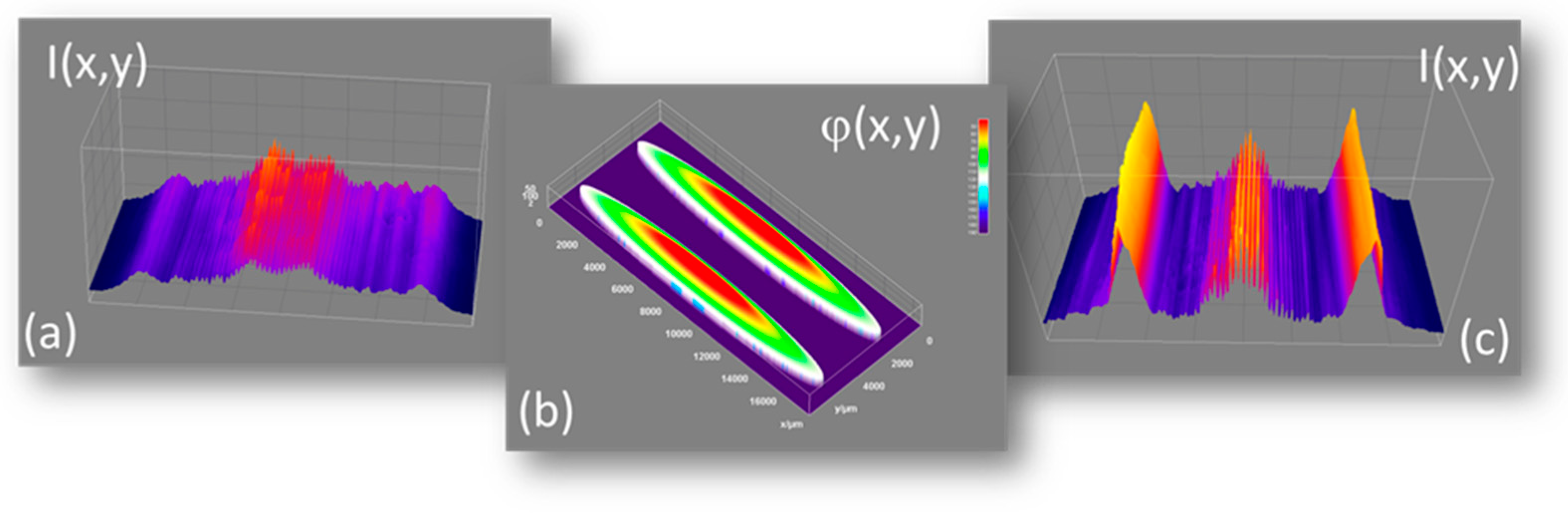
Figure 3 shows the light concentration for
Com1 in two separated lines in the far field profile by illuminating a Fresnel mirror with a pair of elliptical axicon profiles programmed in the phase map of the LCoS-SLM.
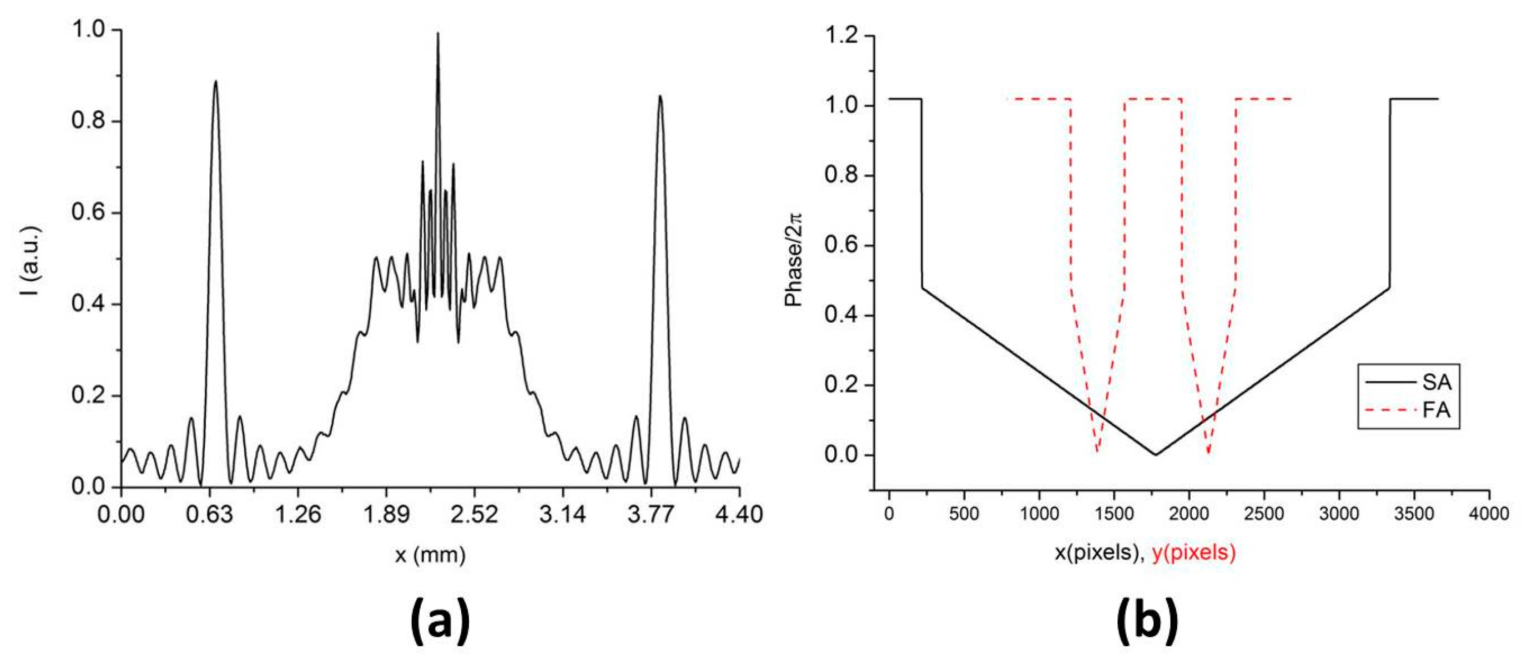
A fast-axis cut through a simulated distribution corresponding to the experimental conditions for
Figure 3c as well as cuts through the related phase profiles of the elliptical axicons (corresponding to
Figure 3b) are plotted in
Figure 4a,b, respectively. Phase as a function of grey values was calibrated from LUT (grey value 255 causes 2π phase stroke at 800 nm). The simulation was performed with virtual lab wave propagation software (LightTrans).
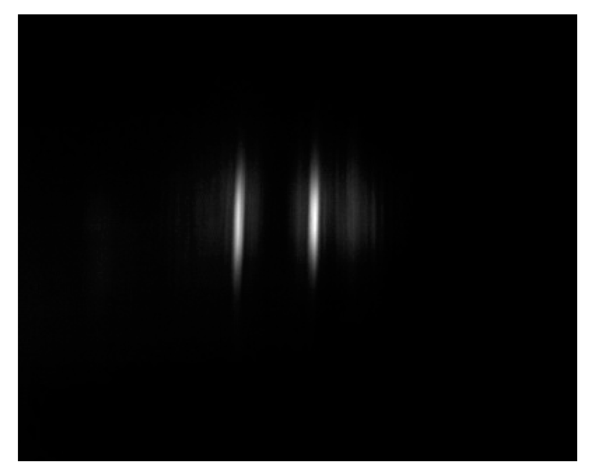
Both the measured and simulated time-integrated intensity profiles already show a significant improvement compared to the unfiltered illumination but still minimal residual side wings of Bessel distributions. The axicons generate quasi-nondiffracting light slices, which interfere in the region of crossing and propagate to the far field that is well separated, if diffraction is sufficiently suppressed (
Figure 5).
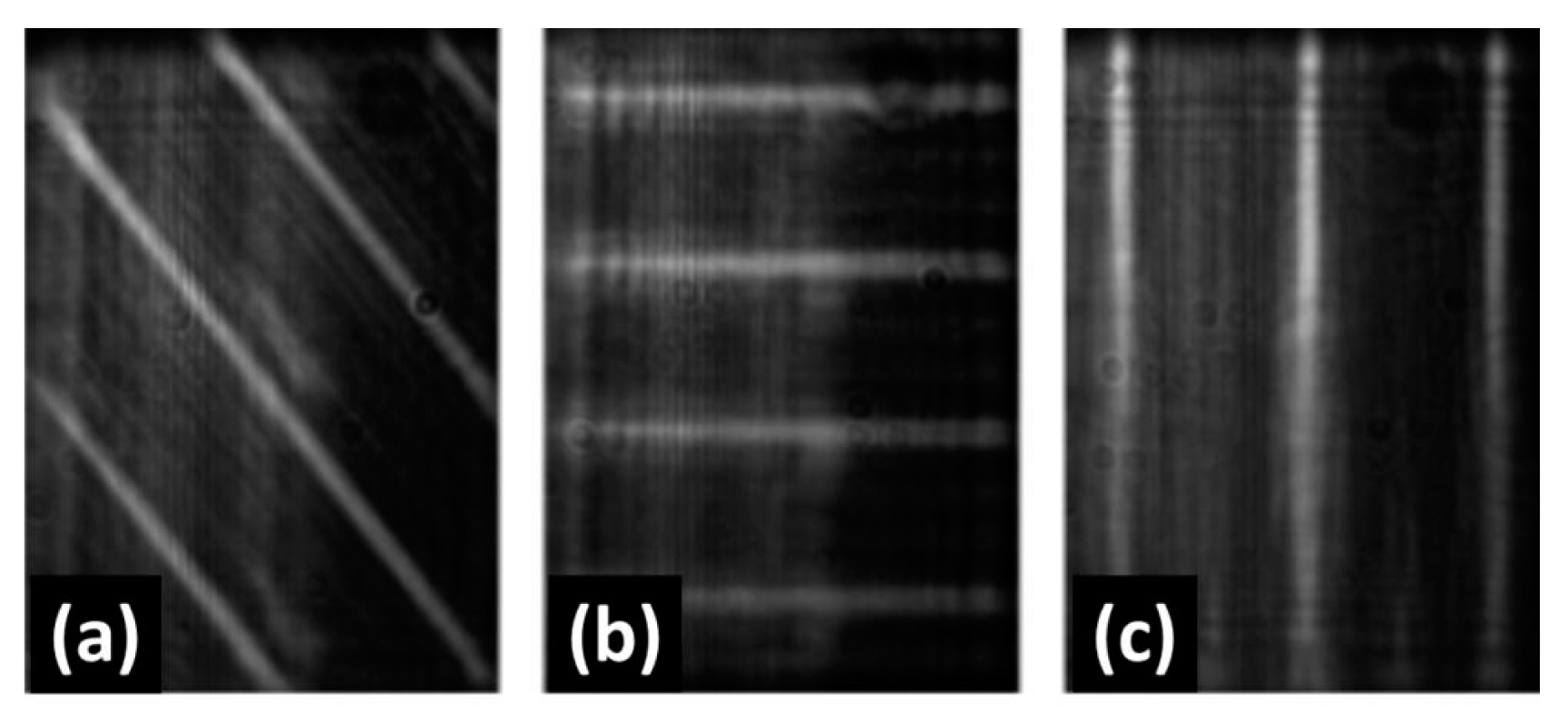
To compensate the 45° angle of incidence and to exactly adapt the linear foci to the target pupil function, size, shape and distance of the axicon lenses were optimized with modified graphics software via gray value distributions and a calibrated look up table (LUT). The directional adaptation by variation of the rotation angle is demonstrated with multiple focal lines in
Figure 6. With the SLM, it was easily possible to adjust arrays of light slices parallel to the edges of rectangular sections of a Fresnel bi-micrror (linear axicon). For a self-apodized illumination of MEMS acting as spiral phase plates (SPPs) in configuration
Com 2, circular or elliptical foci have to be shaped by toroidal phase profiles.
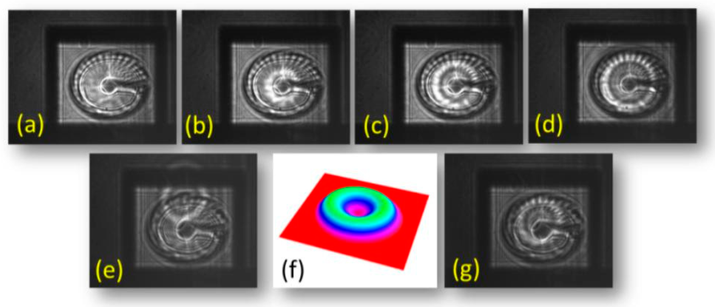
Figure 7 shows the variation of the diameter (a–d), a radial translation of the ring focus (e,g) and a typical torus lens profile (f). The thermally tunable spiral phase plate was designed for the generation of orbital angular momentum beams with tunable topological charge.
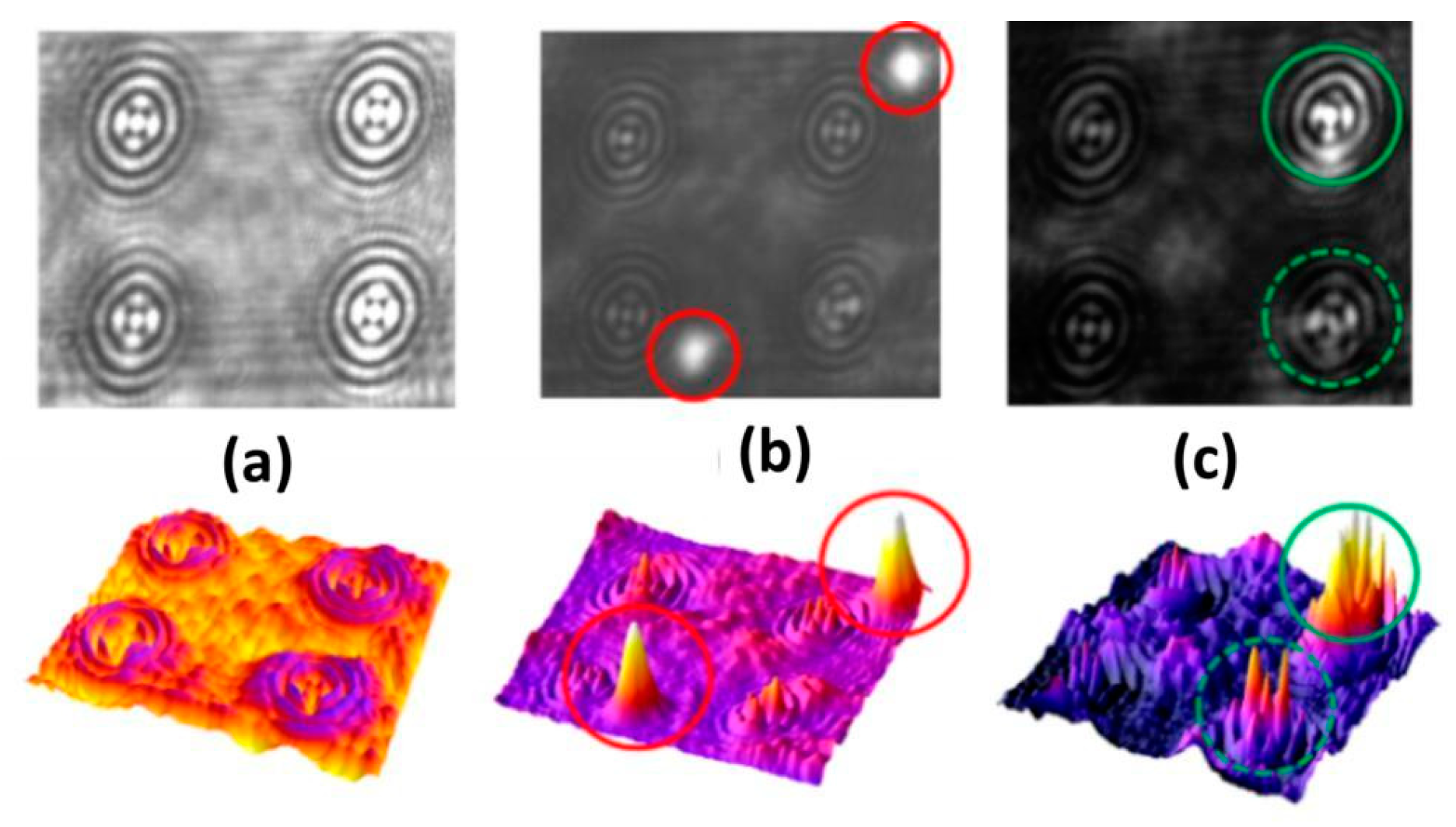
In
Figure 8, three different cases of illumination of a 4 × 4 MEMS axicon array are drawn corresponding to
Com 3. With quasi-uniform illumination (
Figure 8a), no background suppression is obtained. The other pictures demonstrate the capability to individually address array elements with programmable needle beams for the cases of arbitrary beam positions (
Figure 8b) and centered beam localization (
Figure 8c).
4.2. Temporal Switching
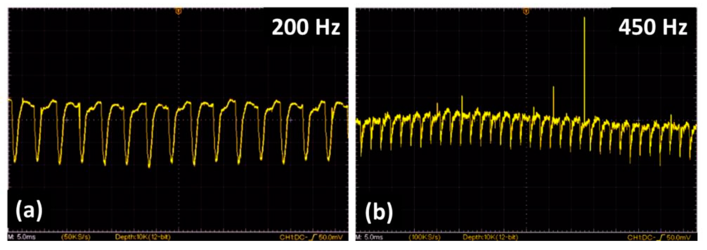
In
Figure 9, the frequency response of a single, piezo-actuated Fresnel-mirror is depicted (
Com 4).
The MEMS was illuminated by a laser diode, and the angular deflection was monitored by a photodiode in the far field. The combination of the slow switching SLM (flickering at about 60 Hz video frequency) and a faster switching MEMS requires one to carefully synchronize the frequency combs to avoid beating effects. Best performance was found in a MEMS frequency range between 100 Hz and 350 Hz, thus demonstrating the capabilities of combining specific advantages of SLM and MEMS in spatial and temporal domains.
4.3. Contrast Management for Non-Collinear Autocorrelation
Combined systems offer the opportunity to circumvent the diffractive distortion of ultrashort pulses by self-apodization. As an application of combined SLM and Fresnel bi-mirror (configuration
Com 1), we studied the possibility to improve the quality of non-collinear autocorrelation of few-cycle pulses. The principle of adaptive non-collinear autocorrelation with flexible Fresnel bi-mirrors was previously published by some of the authors [
52]. Arrangement and signal analysis are described in this reference. To demonstrate the potential of pre-structuring the illuminating beam, we compare unoptimized and optimized second harmonic interference patterns generated with pulses of a Ti:sapphire oscillator (
Figure 10).
Diffraction at the edges can mostly be eliminated. Information about second-order field autocorrelation can be derived from averaged horizontal cuts through the intensity profiles [
52].
4.4. Tunable Nondiffracting Talbot Effect
Contrary to the well-known diffractive self-imaging or Talbot effect [
47,
48,
49], the coherent geometrical superposition of conical Bessel-like needle beams also results in periodical revivals of periodical phase and/or amplitude patterns, which appear at particular distances [
51]. These distances depend on the conical beam angle (which is determined by the phase profile of the axicons programmed into the SLM) and the divergence of the illuminating laser beam. Because of its non-diffracting nature, the phenomenon can be used to transfer temporal information of ultrashort pulses from near-field to far-field distances, or to realize laser-matter interactions at ultrashort pulse duration far from the beam shaper. By changing the illumination divergence or convergence, the nondiffracting Talbot distances can be shifted. This adaptive approach makes the technique more attractive for applications such as optical tweezing, filamentation, coupling or wavefront diagnosis. In the experiments, arrays with central holes were programmed to enable for easier centering and identifying the order of self-imaging. The geometry of parts of a hexagonal and an orthogonal array is shown in
Figure 11.
A tunable, piezo-actuated fluid lens (SLM04, IMTEK) was positioned 5 cm in front of the SLM. By changing the voltage at the piezo-actuator, the angular distribution of the input beam at the SLM was tuned up to a maximum value of 75 V (at higher voltages, the beam quality was found to be significantly reduced by aberrations). The beam propagation was analyzed by detecting the distance-dependent intensity patterns on the CCD camera (5 cm behind the SLM). The laser intensity was adjusted with a polarizer.
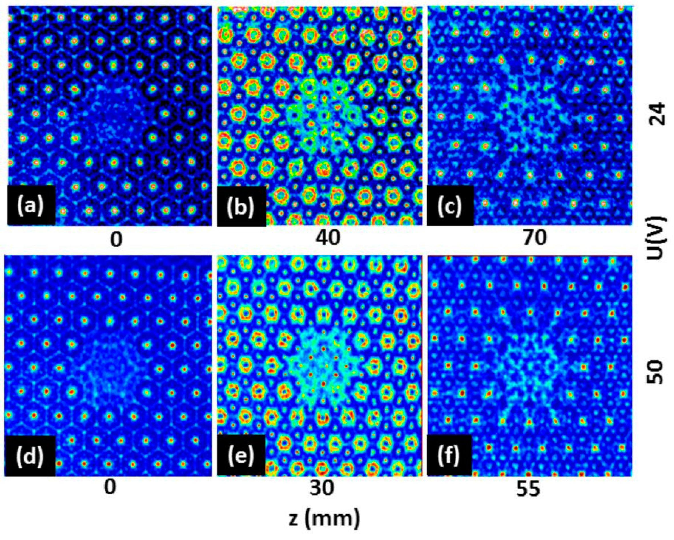
Figure 12 for the hexagonal array shows how the nondiffracting self-imaging planes are shifted to smaller distances to the SLM with increasing voltage. In
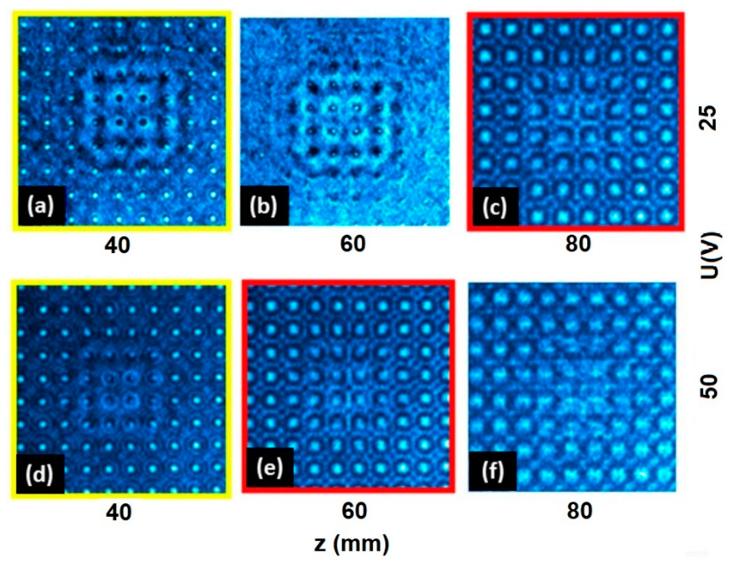
Figure 13, the distances are kept constant and the patterns change with increasing voltage. One has to note equivalent patterns in both cases, which indicate that self-imaging appears at different distances depending on the lens voltage.
Additionally, a number of specific problems were identified that have to be taken into account for further improvements: (i) the background generated by diffraction at the pixels of the SLM; (ii) reflection at interspaces between MEMS elements in arrays; (iii) temporal phase flickering of pulsed SLM because of liquid crystal viscosity; and (iv) strong angular dependence of programmed DOE, e.g., astigmatic spiral phase gratings. With the SLM, a background suppression was obtained by programming check-patterns as 2D gratings into structure-less areas or gaps and by appropriately modifying the phase contrast between pixels and structures. Flickering of liquid crystal devices could be influenced by temperature control.
5. Conclusions
To conclude, the highly flexible generation of structured light fields with tandem arrangements of adaptive phase-shaping components was demonstrated. The particular goal of the experiments was to achieve synergetic effects by combining specific advantages of high-resolution phase-only spatial light modulators and different types of piezo-actuated or thermally driven MEMS mirrors and lenses. The capability to efficiently reduce diffraction by self-apodization and to control propagation properties by tuning angular profiles were experimentally verified. Self-apodization enables the generation of high-quality nondiffracting beams or wavepackets, which we refer to as “doubly non-diffracting beams”. The prize one has to pay for reduced losses and improved pulse transfer is the enhancement of the angular divergence of the shaped beams. Therefore, the concept is of particular interest for applications that tolerate wavefront transformation or preferentially utilize the near field. At extremely short pulse durations, space-time coupling effects have to be additionally compensated for. In our opinion, the beam quality factor
M2 can only be applied to simple types of beams such as the Gaussian beam or the Bessel beam. In practice, the statistical description neglects important features of the shaped beams such as rippled substructure and temporal or spectral effects. For a confined analysis of the beam quality, the space-bandwidth-product could also be involved, which is known from signal theory [
53].
By combining programmable axicon arrays with a fluid lens of tunable focal length, nondiffracting self-imaging was extended towards variable Talbot distances. This approach could find applications in micromanipulation, filamentation or adaptive wavefront sensing.
Involving the control of amplitude or polarization maps will further enhance the number of free parameters. We would like to mention that, in recently reported studies of other groups,
amplitude- and
phase-shaping were simultaneously realized by two SLMs [
16] or by using a DMD for programmable laser heating of a thermally deformable mirror [
54]. Considering the specific properties of the diverse types of beam shapers, the combination of DMDs with SLMs and/or MEMS promises to be another fruitful concept for the future.
To sum up, on the basis of first exploring studies, it has to be expected that combined and integrated adaptive optical systems will essentially contribute to advanced applications of ultrashort and intense pulsed lasers.
Author Contributions
Conceptualization, R.G., M.B., M.L. and U.W.; methodology, R.G., M.B. and M.L.; software, M.B., M.J.; electronics, B.P.B. and M.J.; design, test and fabrication of MEMS, B.P.B., H.G. and U.W.; experiments and data analysis, R.G., M.L., M.J. and H.G.; writing—original draft preparation, R.G.; writing—review and editing, R.G. and U.W.; visualization, R.G. and M.J.; supervision, project administration and funding acquisition, R.G. and U.W. All authors have read and agreed to the published version of the manuscript.
Funding
This research was funded by German Research Foundation (DFG), project MAXWELL III, grant numbers GR1782/16-1, WA 1657/6-2 and WA1657/11-1.
Data Availability Statement
Data underlying the simulation results presented in this paper are not publicly available at this time but may be obtained from the authors upon reasonable request.
Acknowledgments
Experimental resources including lab space and laser systems were kindly provided by Elsaesser and Erik Nibbering (MBI). We thank Alexander Treffer for technical support and helpful discussions. The authors acknowledge support for microscopic characterization of components by Dieter Engel and Sandy Schwirzke-Schaaf (MBI). Furthermore, we thank Peter Scholze (MBI) for designing and manufacturing sophisticated mechanical mounts.
Conflicts of Interest
The authors declare no conflict of interest.
References
- Forbes, A.; de Oliveira, M.; Dennis, M. Structured Light. Nat. Photon. 2021, 15, 253–262. [Google Scholar] [CrossRef]
- Rubinsztein-Dunlop, H.; Forbes, A.; Berry, M.V.; Dennis, M.R.; Andrews, D.L.; Mansuripur, M.; Danz, C.; Alpmann, C.; Banzer, P.; Bauer, T. Roadmap on structured light. J. Opt. 2017, 19, 013001. [Google Scholar] [CrossRef]
- Scholes, S.; Sroor, H.; Ait-Ameur, K.; Zhan, Q.; Forbes, A. General design principle for structured light lasers. Opt. Express 2020, 28, 35006–35017. [Google Scholar] [CrossRef] [PubMed]
- Scholes, S.; Rodriguez-Fajardo, V.; Forbes, A. Lossless reshaping of structured light. J. Opt. Soc. Am. A 2020, 37, C80–C85. [Google Scholar] [CrossRef] [PubMed]
- Dev, V.; Reddy, A.N.K.; Pal, V. Generation of uniform-intensity light beams with controllable spatial shapes. Opt. Commun. 2020, 475, 126226. [Google Scholar] [CrossRef]
- Gong, L.; Ren, Y.-X.; Xue, G.-S.; Wang, Q.-C.; Zhou, J.-H.; Zhong, M.-C.; Wang, Z.-Q.; Li, Y.-M. Generation of nondiffracting Bessel beam using digital micromirror device. Appl. Opt. 2013, 52, 4566–4574. [Google Scholar] [CrossRef]
- Chen, Y.; Fang, Z.-X.; Ren, Y.-X.; Gong, L.; Lu, R.-D. Generation and characterization of a perfect vortex beam with a large topological charge through a digital micromirror device. Appl. Opt. 2015, 54, 8030–8035. [Google Scholar] [CrossRef]
- Ren, Y.-X.; Lu, R.-D.; Gong, L. Tailoring light with a digital micromirror device. Ann. Phys. 2015, 527, 447–470. [Google Scholar] [CrossRef]
- Scholes, S.; Kara, R.; Pinnell, J.; Rodriguez-Fajardo, V.; Forbes, A. Structured light with digital micromirror devices: A guide to best practice. Opt. Eng. 2019, 59, 041202. [Google Scholar] [CrossRef]
- Larkin, A.S.; Pushkarev, D.V.; Degtyarev, S.A.; Khonina, S.N.; Savel’ev, A.B. Generation of Hermite-Gaussian modes of high-power femtosecond laser radiation using binary-phase diffractive optical elements. Quant. Electron. 2016, 46, 733–737. [Google Scholar] [CrossRef]
- Rodriguez-Fajardo, V.; Scholes, S.; Kara, R.; Pinnell, J.; Rosales-Guzmán, C.; Mashaba, N.; Nape, I.; Forbes, A. Controlling light with DMDs. In Proceedings of the 2020 International Conference Laser Optics (ICLO), St. Petersburg, Russia, 2–6 November 2020. [Google Scholar]
- Hu, S.; Xu, B.; Zhang, X.; Hou, J.; Wu, J.; Jiang, W. Double-deformable-mirror adaptive optics system for phase compensation. Appl. Opt. 2006, 45, 2638–2642. [Google Scholar] [CrossRef]
- Zou, W.; Qi, X.; Burns, S.A. Woofer–tweeter adaptive optics scanning laser ophthalmoscopic imaging based on Lagrangemultiplier damped least-squares algorithm. Biomed. Opt. Express 2011, 2, 1986–2004. [Google Scholar] [CrossRef]
- Li, Q.; Reinig, M.; Kamiyama, D.; Huang, B.; Tao, X.; Bardales, A.; Kubby, J. Woofer–tweeter adaptive optical structured illumination microscopy. Photonics Res. 2017, 5, 329–334. [Google Scholar] [CrossRef]
- Rajaeipour, P.; Banerjee, K.; Dorn, A.; Zappe, H.; Ataman, Ç. Cascading optofluidic phase modulators for performance enhancement in refractive adaptive optics. Adv. Photon. 2020, 2, 066005. [Google Scholar] [CrossRef]
- Ackermann, L.; Roider, C.; Schmidt, M. Uniform and efficient beam shaping for high-energy lasers. Opt. Express 2021, 29, 17997–18009. [Google Scholar] [CrossRef]
- Linden, J.; Cohen, S.; Berg, Y.; Peled, I.; Kotler, Z.; Zalevsky, Z. High-Speed Temporal and Spatial Beam-Shaping Combining Active and Passive Elements. Opt. Express 2021, 29, 31229–31239. [Google Scholar] [CrossRef] [PubMed]
- Wang, H.; Sheppard, C.J.R.; Ravi, K.; Ho, S.T.; Vienne, G. Fighting against diffraction: Apodization and near field diffraction structures. Laser Photonics Rev. 2012, 6, 354–392. [Google Scholar] [CrossRef]
- Jacquinot, P.; Roizen-Dossier, B. Apodisation. In Progress in Optics; Wolf, E., Ed.; Elsevier: Amsterdam, The Netherlands, 1964; Volume 3, p. 29. [Google Scholar]
- Reddy, A.N.K.; Hashemi, M. Apodization pupils: Design and performance (review). J. Phys. Conf. Ser. 2019, 1096, 012140. [Google Scholar] [CrossRef]
- Asakura, T. Diffraction patterns by non-uniform phase and amplitude aperture illumination (I). Oyo Butsuri 1962, 31, 730. [Google Scholar]
- Cagigas, M.A.; Valle, P.J.; Cagigal, M.P. Super-Gaussian apodization in ground based telescopes for high contrast coronagraph imaging. Opt. Express 2013, 21, 12744–12756. [Google Scholar] [CrossRef][Green Version]
- Cao, Q.; Jahns, J. Apodized multilevel diffractive lenses that produce desired diffraction-limited focal spots. J. Opt. Soc. Am. A 2006, 23, 179–186. [Google Scholar] [CrossRef] [PubMed]
- Zucker, H. Optical resonators with variable reflectivity mirrors. Bell Syst. Tech. J. 1970, 49, 2349–2376. [Google Scholar] [CrossRef]
- Snell, K.J.; McCarthy, N.; Piché, M.; Lavigne, P. Single transverse mode oscillation from an unstable resonator Nd: YAG-laser using a variable reflectivity mirror. Opt. Commun. 1988, 65, 377–382. [Google Scholar] [CrossRef]
- Degtyarev, S.A.; Porfirev, A.P.; Khonina, S.N.; Karpeev, S.V. Demonstration of vortical beams spectral stability formed in non-zero diffraction orders. J. Phys. Conf. Ser. 2016, 745, 012023. [Google Scholar] [CrossRef]
- Melcher, R.L. LCoS microdisplay technology and applications. Inf. Disp. 2000, 16, 20–23. [Google Scholar]
- Hermerschmidt, A.; Osten, S.; Krüger, S.; Blümel, T. Wave front generation using a phase-only modulating liquid-crystal-based micro-display with HDTV resolution. Proc. SPIE 2007, 6584, 65840E. [Google Scholar]
- Bleha, W.P., Jr.; Lei, L.A. Advances in liquid crystal on silicon (LCoS) spatial light modulator technology. Proc. SPIE 2013, 8736, 87360A. [Google Scholar]
- Hermerschmidt, A.; Lazarev, G.; Rozhkov, O.V. LC-based Phase-modulating Spatial Light Modulators. In Proceedings of the Digital Holography and Three-Dimensional Imaging 2014, Seattle, WA, USA, 13–17 July 2014. [Google Scholar]
- Wang, M.; Zong, L.; Mao, L.; Marquez, A.; Ye, Y.; Zhao, H.; Caballero, F.J.V. LCoS SLM study and its application in wavelength selective switch. Photonics 2017, 4, 22. [Google Scholar] [CrossRef]
- Lazarev, G.; Chen, P.-J.; Strauss, J.; Fontaine, N.; Forbes, A. Beyond the display: Phase-only liquid crystal on silicon devices and their applications in photonics. Opt. Express 2019, 27, 16206–16249. [Google Scholar] [CrossRef]
- Mishra, M.K.; Dubey, V.; Mishra, P.M.; Khan, I. MEMS technology: A review. J. Eng. Res. Rep. 2019, 4, 1–24. [Google Scholar] [CrossRef]
- Brunne, J.; Wapler, M.; Grunwald, R.; Wallrabe, U. A tunable piezoelectric Fresnel mirror for high-speed lineshaping. J. Micromech. Microeng. 2013, 23, 115002. [Google Scholar] [CrossRef]
- Brunne, J.; Wallrabe, U. Tunable MEMS axicon mirror arrays. Opt. Lett. 2013, 38, 1939–1941. [Google Scholar] [CrossRef] [PubMed]
- Grunwald, R.; Bock, M.; Brunne, J.; Wallrabe, U. Few-cycle vortex wavepackets with tunable topological charge. Proc. SPIE 2014, 8999, 89990W. [Google Scholar]
- Bruno, B.P.; Schütze, R.; Grunwald, R.; Wallrabe, U. Micro Fresnel mirror array with individual mirror control. Smart Mat. Struct. 2020, 29, 075003. [Google Scholar] [CrossRef]
- Bruno, B.P.; Treffer, A.; Grunwald, R.; Wallrabe, U. Thermally actuated free-form MEMS mirrors. In Proceedings of the 2019 International Conference on Optical MEMS and Nanophotonics, Daejeon, Korea, 28 July–1 August 2019; pp. 82–83. [Google Scholar]
- Bruno, B.P.; Grunwald, R.; Wallrabe, U. Fabrication of an Adaptive Micro Fresnel Mirror Array. In Progress in Optomechatronic Technologies; Springer Proceedings in Physics; Martínez-García, A., Bhattacharya, I., Otani, Y., Tutsch, R., Eds.; Springer: Singapore, 2019; Volume 233, pp. 29–35. [Google Scholar]
- Durnin, J.; Miceli, J.J.; Eberly, J.H. Diffraction-free beams. Phys. Rev. Lett. 1987, 58, 1499–1501. [Google Scholar] [CrossRef]
- Bock, M.; Das, S.K.; Grunwald, R. Adaptive generation and diagnostics of linear few-cycle light bullets. Appl. Sci. 2013, 3, 139–152. [Google Scholar] [CrossRef]
- Grunwald, R.; Bock, M. Needle beams: A review. Adv. Phys. X 2020, 5, 1736950. [Google Scholar] [CrossRef]
- Bock, M.; Das, S.K.; Grunwald, R. Ultrashort highly localized wavepackets. Opt. Express. 2012, 20, 12563–12578. [Google Scholar] [CrossRef]
- Grunwald, R.; Bock, M.; Kebbel, V.; Huferath, S.; Neumann, U.; Steinmeyer, G.; Stibenz, G.; Néron, J.-L.; Piché, M. Ultrashort-pulsed truncated polychromatic Bessel-Gauss beams. Opt. Express 2008, 16, 1077–1089. [Google Scholar] [CrossRef]
- Grunwald, R. Thin-Film Microoptics—New Frontiers of Spatio-Temporal Beam Shaping; Elsevier: Amsterdam, The Netherlands, 2007; pp. 147–151. [Google Scholar]
- Gori, F.; Guattari, G.; Padovani, C. Bessel-Gauss beams. Opt. Commun. 1987, 64, 1499–1501. [Google Scholar] [CrossRef]
- Talbot, H.F. LXXVI. Facts relating to optical science. No. IV. Lond. Edinb. Dublin Philos. Mag. J. Sci. 1836, 9, 401–407. [Google Scholar] [CrossRef]
- Winthrop, J.T.; Worthington, C.R. Theory of Fresnel images. I. Plane periodic objects in monochromatic light. J. Opt. Soc. Am. 1965, 55, 373–381. [Google Scholar] [CrossRef]
- Montgomery, W.D. Self-imaging objects of infinite aperture. J. Opt. Soc. Am. 1967, 57, 772–778. [Google Scholar] [CrossRef]
- Grunwald, R.; Neumann, U.; Bock, M.; Steinmeyer, G. Young’s interference experiment with ultrashort-pulsed Bessel beams. In Proceedings of the 2007 Conference on Lasers and Electro-Optics (CLEO), Baltimore, MD, USA, 6–11 May 2007. [Google Scholar]
- Bock, M.; Treffer, A.; Grunwald, R. Nondiffracting self-imaging of ultrashort wavepackets. Opt. Lett. 2017, 42, 2374–2377. [Google Scholar] [CrossRef]
- Treffer, A.; Brunne, J.; Bock, M.; König, S.; Wallrabe, U.; Grunwald, R. Adaptive non-collinear autocorrelation of few-cycle pulses with an angular tunable bi-mirror. Appl. Phys. Lett. 2016, 108, 051103. [Google Scholar] [CrossRef]
- Mahnke, P.; Schmid, M. Analytic model of a laser-controlled thermally deformable mirror. J. Opt. Soc. Am. A 2021, 38, 840–843. [Google Scholar] [CrossRef]
- Lohmann, A.W.; Dorsch, R.G.; Mendlovic, D.; Zalevsky, Z.; Ferreira, C. Space-bandwidth product of optical signals and systems. J. Opt. Soc. Am. A 1996, 13, 470–473. [Google Scholar] [CrossRef]
Figure 1.
Principle of self-apodization with a truncated Bessel beam. Diffraction at hard edges of an aperture is minimized by adaptive beam pre-shaping. The light profile acts as the filter function (schematically). (
a) unfiltered Bessel beam, (
b) truncated Bessel beam. For a thin circular aperture at monochromatic illumination, a special self-apodization condition is well-approximated by a truncated Bessel function with first zero radius equal to the aperture radius [
44,
45].
Figure 2.
Combined system containing a high-resolution LCoS-SLM and a shape-variable MEMS corresponding to configuration Com 1 (schematically). As an example, the drawn MEMS represents a Fresnel bi-mirror. Beam shaping is evaluated with a CCD camera. The nonlinear crystal symbolizes the options for additional nonlinear processing—here, the extraction of SHG autocorrelation signal. In general, the MEMS can be a single or multiple reflective or transmissive structure.
Figure 3.
Structured illumination in configuration Com 1: a pair of elliptical cylinder axicons was programmed into the SLM phase map (center, b) to illuminate both parts of a MEMS Fresnel bi-mirror (area of partial mirrors: 2.5 × 5 mm2). The comparison of the distorted intensity profile at a distance close to the overlapping zone without (left, a) and with pre-shaping (right, c) shows a significant improvement of the beam quality and the effect of self-apodization, i.e., a reduced diffraction by generating minimum intensity at the mirror edges (distance 5 cm, diode laser emitting at 790 nm central wavelength, and field of view 4.4 × 4.4 mm2).
Figure 4.
Simulation of the beam propagation for configuration
Com 1. (
a) Distribution approximately corresponding to the experimental conditions for
Figure 3c; (
b) cuts through the fast axis (FA) and slow axis (SA) phase profiles of the elliptical axicons.
Figure 4.
Simulation of the beam propagation for configuration
Com 1. (
a) Distribution approximately corresponding to the experimental conditions for
Figure 3c; (
b) cuts through the fast axis (FA) and slow axis (SA) phase profiles of the elliptical axicons.
Figure 5.
Measured far field distribution at a distance of 5.5 cm behind the SLM after optimizing the axicon parameters for configuration Com 1 (field of view: 7.03 × 5.62 mm2). The distance between the maxima is 953 µm.
Figure 5.
Measured far field distribution at a distance of 5.5 cm behind the SLM after optimizing the axicon parameters for configuration Com 1 (field of view: 7.03 × 5.62 mm2). The distance between the maxima is 953 µm.
Figure 6.
Rotation of the structured illumination for configuration Com 1: three selected orientations of focal lines on the Fresnel-mirror shaped by SLM graphics software: (a) diagonal, (b) perpendicular and (c) parallel to the contact line of the partial mirrors of the Fresnel bi-mirror.
Figure 6.
Rotation of the structured illumination for configuration Com 1: three selected orientations of focal lines on the Fresnel-mirror shaped by SLM graphics software: (a) diagonal, (b) perpendicular and (c) parallel to the contact line of the partial mirrors of the Fresnel bi-mirror.
Figure 7.
Configuration Com 2: a torus-like phase map (SLM, f) was used to generate a flexible ring focus on a spiral phase plate (SPP, diameter 2.9 mm, distance SLM-SPP: 15.5 cm, angle of incidence: 21°, distance between SPP and detector plane: 5 cm). By varying radius (a–d) and decenter (e,g), the optimum performance was approximated (c).
Figure 8.
Configuration Com 3: individually addressable configurations were realized by flexibly positioning SLM-generated needle beams (i.e., single-maximum Bessel beams) on the elements of a 4 × 4 MEMS axicon array (pitch: 1 mm). The axicons were illuminated by an approximated plane wave (a), two arbitrarily displaced needle beams of different intensity (b), and the same two sub-beams centered at two selected axicons (c).
Figure 9.
Dynamic behavior. Configuration Com 4 combines the high-resolution spatial shaping of the SLM and the fast-switching capability of the MEMS. The frequency response of combined SLM and Fresnel-mirror is shown as oscilloscope traces for two selected frequencies: (a) 200 Hz and (b) 450 Hz (time interval 75 ms in both cases). Far field oscillation was detected by a fast photodiode. At higher frequencies, the signal of the unscreened detector was slightly distorted by electromagnetic interference (laser source: diode laser, 790 nm).
Figure 10.
Improvement of interference contrast generated with configuration Com 1 at pulsed illumination by adapting grey level maps and background levels on SLM (a,c) unoptimized and (b,d) optimized intensity maps as 2D and 3D plots (laser source: Ti: sapphire laser oscillator; 7 fs pulses; distance from mirror: 15 cm; frequency conversion: BBO; voltage at Fresnel bi-mirror: 104.5 V; and FOV: 1.375 × 0.825 mm2).
Figure 11.
Hexagonal (a) and orthogonal (b) arrays of elliptical axicons programmed into the SLM phase map for the generation of nondiffracting needle beams (parts of larger arrays, optimized for 45° illumination, and 790 nm diode laser). In the central regions, a few elements (7 and 9, respectively) were eliminated to enable for centering the system, identifying the order of self-imaging and visualizing residual diffraction effects (FOV on the SLM: 3.3 × 3.3 mm2).
Figure 12.
Configuration Com 5: Experimental demonstration of tunable nondiffracting self-imaging with a hexagonal axicon array programmed into the SLM and an illumination by a fluid lens of electrically steerable focal length. The pictures show the voltage-dependent axial shift of the integer self-imaging planes and an intermediate fractal plane corresponding to alternating phases (FOV about 3.3 × 3.3 mm on CCD detector, spatial scales slightly adapted to show the geometrical similarity). The different distances for two voltages 24 V (a–c) and 50 V (d–f) indicate the axial tuning (laser source: diode laser, 790 nm).
Figure 13.
Configuration
Com 5: Experimental demonstration of tunable nondiffracting self-imaging with an orthogonal axicon array: interference patterns at three different distances for two different voltages at the tunable lens (FOV: 3.3 × 3.3 mm on CCD detector, laser source: diode laser, 790 nm). Contrary to
Figure 12, different patterns appear at different voltages for equal distances (compare
a–
c and
d–
f).
Table 1.
Overview of different types of combined systems tested in beam shaping experiments. All arrangements consisted of a high-spatial-resolution, pixelated, phase-only liquid-crystal-on-silicon spatial light modulator (LCoS-SLM, HOLOEYE) and a particular type of actuated optical component (MEMS, IMTEK).
| | SLM | MEMS |
|---|
| Com1 | LCoS, 10 Megapixels | Piezo-actuated Fresnel bi-mirror |
| Com2 | LCoS, 10 Megapixels | Thermally actuated spiral phase plate (SPP) |
| Com3 | LCoS, 10 Megapixels | Piezo-actuated Axicon mirror array (2 × 2) |
| Com4 | LCoS, 10 Megapixels | Piezo-actuated Fresnel mirror array (2 × 2) |
| Com5 | LCoS, 10 Megapixels | Piezo-actuated fluid lens |
| Publisher’s Note: MDPI stays neutral with regard to jurisdictional claims in published maps and institutional affiliations. |
© 2022 by the authors. Licensee MDPI, Basel, Switzerland. This article is an open access article distributed under the terms and conditions of the Creative Commons Attribution (CC BY) license (https://creativecommons.org/licenses/by/4.0/).

 ,
, 


