Article

Photonic Jet-Shaped Optical Fiber Tips versus Lensed Fibers

by
Djamila Bouaziz
1,2,3,*,
Grégoire Chabrol
1,4,
Assia Guessoum
2,
Nacer-Eddine Demagh
2 and
Sylvain Lecler
1,3
1
ICube Research Institute, University of Strasbourg, CNRS, 67412 Illkirch, France
2
Applied Optics Laboratory, Ferhat Abbas University Setif 1, Setif 19000, Algeria
3
INSA de Strasbourg, 67000 Strasbourg, France
4
ECAM Strasbourg-Europe, 67300 Schiltigheim, France
*
Author to whom correspondence should be addressed.
Photonics 2021, 8(9), 373; https://doi.org/10.3390/photonics8090373
Submission received: 6 August 2021 / Revised: 26 August 2021 / Accepted: 29 August 2021 / Published: 7 September 2021
(This article belongs to the Special Issue Photonic Jet: Science and Application)

Abstract

:
Shaped optical fiber tips have recently attracted a lot of interest for photonic jet light focusing due to their easy manipulation to scan a sample. However, lensed optical fibers are not new. This study analyzes how fiber tip parameters can be used to control focusing properties. Our study shows that the configurations to generate a photonic jet (PJ) can clearly be distinguished from more classical-lensed fibers focusing. PJ is a highly concentrated, propagative light beam, with a full width at half maximum (FWHM) that can be lower than the diffraction limit. According to the simulations, the PJs are obtained when light is coupled in the guide fundamental mode and when the base diameter of the microlens is close to the core diameter. For single mode fibers or fibers with a low number of modes, long tips with a relatively sharp shape achieve PJ with smaller widths. On the contrary, when the base diameter of the microlens is larger than the fiber core, the focus point tends to move away from the external surface of the fiber and has a larger width. In other words, the optical system (fiber/microlens) behaves in this case like a classical-lensed fiber with a larger focus spot size. The results of this study can be used as guidelines for the tailored fabrication of shaped optical fiber tips according to the targeted application.

1. Introduction

The term photonic jet (PJ) was first coined by Z. Chen et al. in 2004 when Modelling cylindrical dielectric structures under plane wave illumination; simulations showed that light can be concentrated at the mesoscale with a full width at half maximum (FWHM) lower than the diffraction limit (< λ /2, where λ is the free space wavelength), and with a power density significantly higher than the incident wave [1,2,3]. The key properties of the PJ include: its position (working distance W D : distance from the tip end to the maximum intensity of the photonic jet), FWHM, light intensity peak value and intensity decay length. The determination of these properties has been the aim of numerous theoretical and experimental studies [4,5,6,7,8,9]. The properties of the PJ depend on the material refractive indexes, the dielectric object geometric shape and size, and on the incidence wavelength [2,10,11]. PJ can be obtained using cyilnders, spheres or non-spherical dielectric objects [11]. The interest of PJ has been demonstrated for applications such as enhanced Raman scattering [12,13,14], fluorescence enhancement [15,16], improvement in optical-disk data storage technology [17,18], in sub-micrometer laser etching process on semiconductors and metals [19,20,21,22], to achieve optical tweezers [23] and many other applications [24].
Unfortunately, the technique is not easy to implement in some industrial processes such as lithography or spectral analysis, where the PJ must scan a sample with a complex pattern. For such applications, the sphere-like object cannot be directly placed on the sample. A mechanical micro-holder or optical tweezers are required to manipulate it accurately [19]. For these reasons, more recently, attention has been paid to PJ generation with waveguides [25] and optical fibers; solutions have been proposed to put the sphere at the end of a hollow-core optical fiber [26,27] or to use an optical fiber with a shaped tip [21,28,29,30,31]. Shaped fiber tips have several advantages: easy to move, no necessary contact with the sample and possibility to collect the backscattered light. Owing to the aforementioned arguments, this technique can become a major solution in industrial processes and characterization such as sub-micron laser processing or high-resolution spectral analysis. Nevertheless, the concept of shaped fiber tips has already been known as microlensed fibers for the past 40 years. Initially, microlensed fibers were extensively exploited to improve the coupling between light sources and optical fibers [32,33,34,35,36]. Microlensed fibers are also used in Optical Coherence Tomography OCT [37], scanning microscopy and spectroscopy [38]. Lensed fibers have been fabricated using a large range of methods including: chemical etching [39], laser heating [40] and electric arc discharge melting [41].
The aim of the present work is to investigate shaped optical fiber tips to identify what distinguishes photonic jet generation from classical-lensed fibers focusing. This study also makes it possible to control the properties of the PJ by optimizing the different parameters of a shaped optical fiber tip.

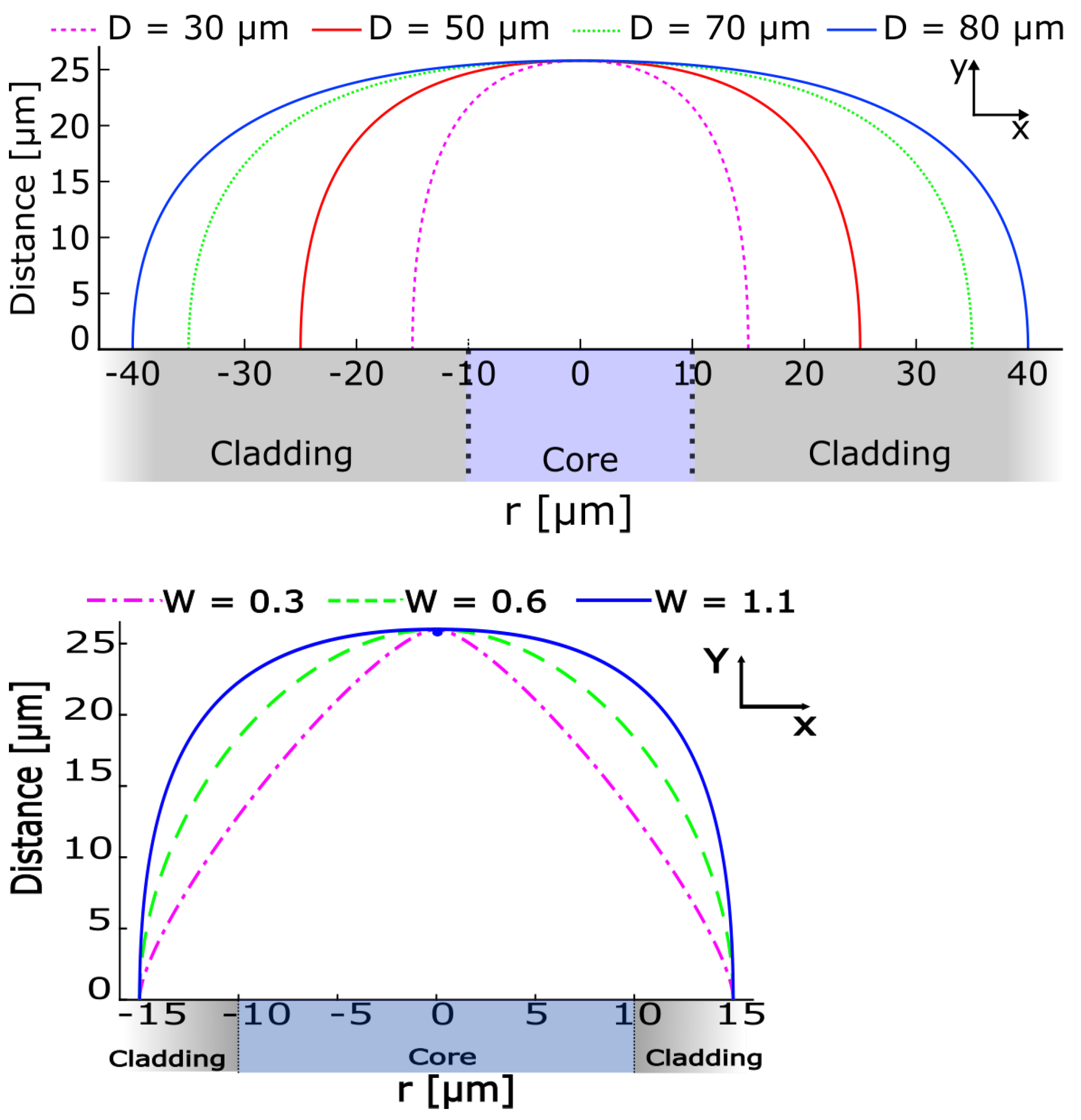
2. Numerical Approach
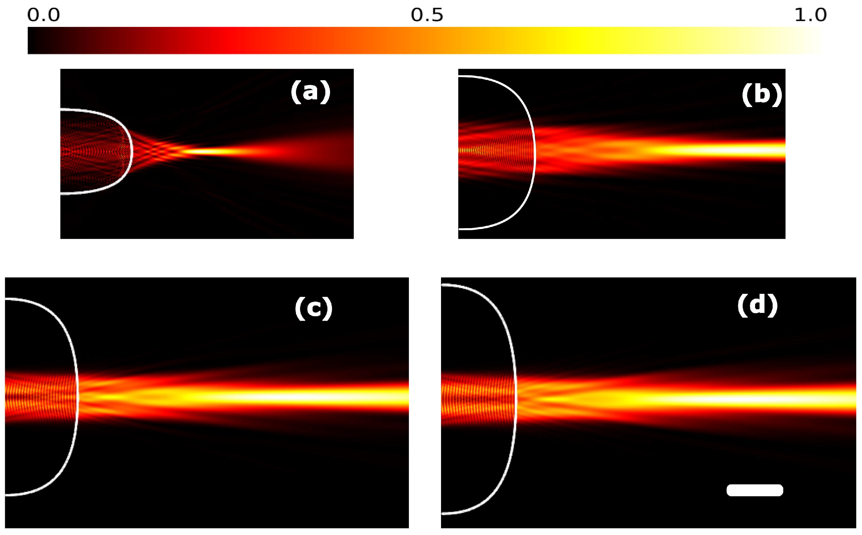
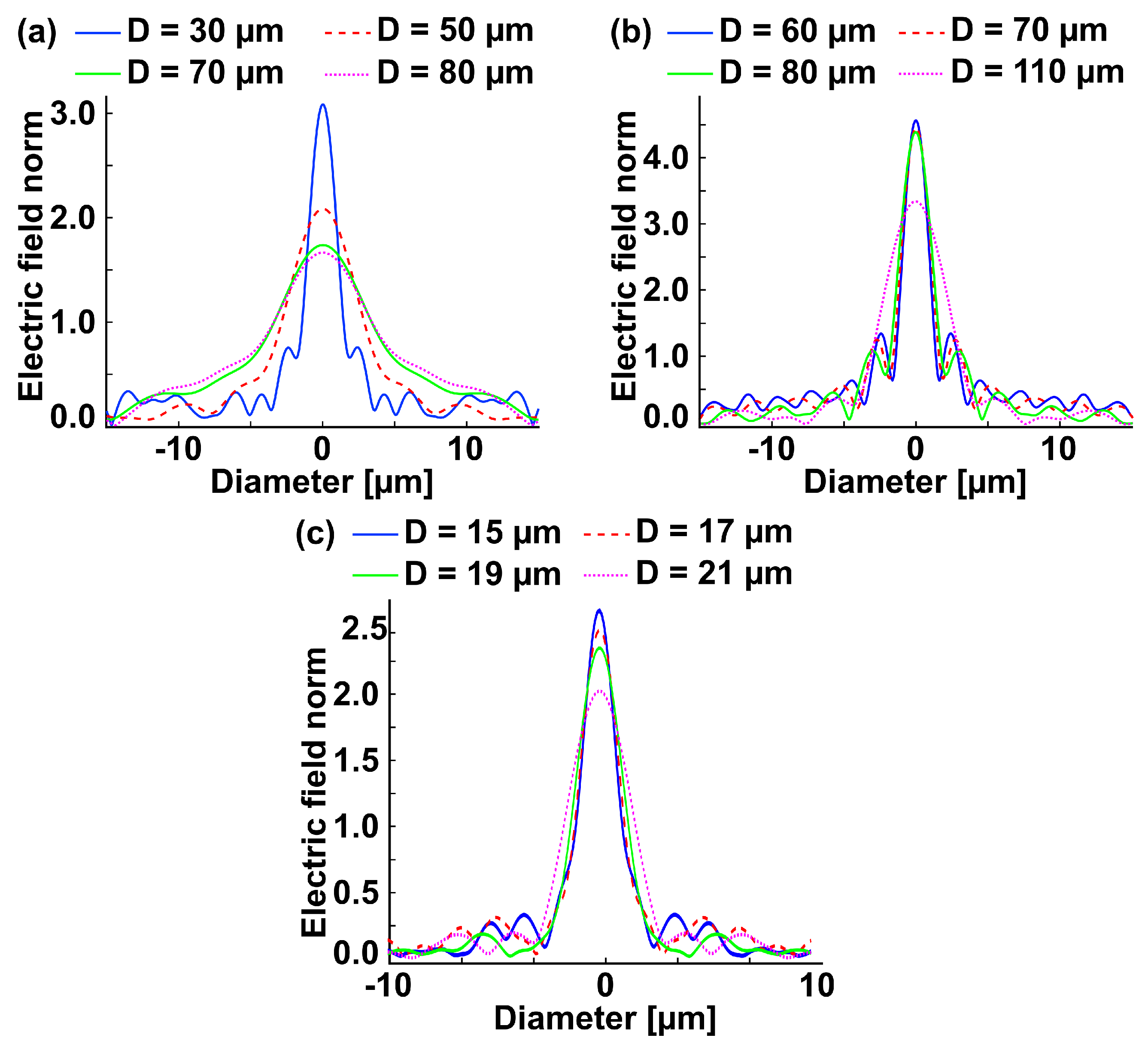
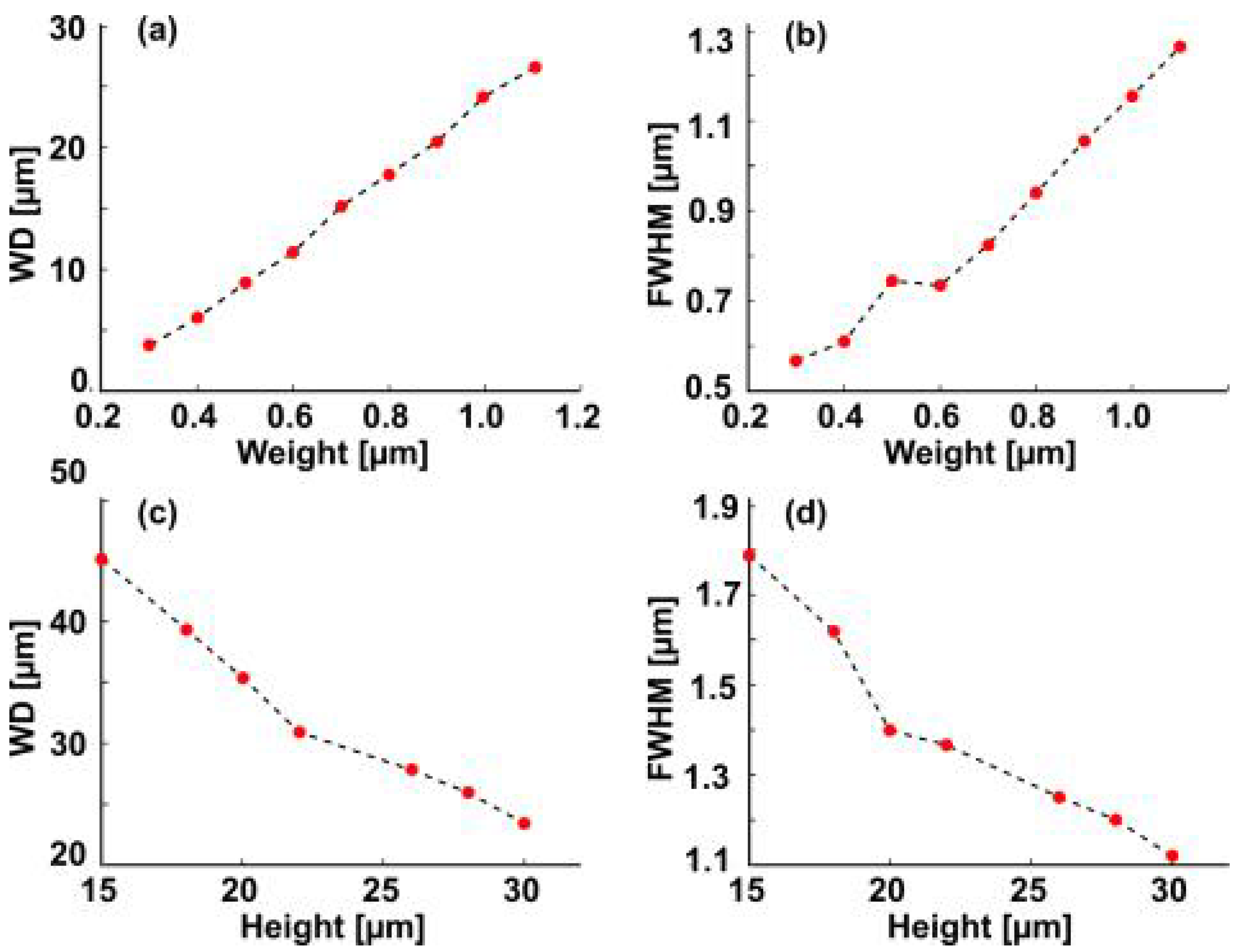
First a multimode silica optical fiber with a low number of modes is considered for 2D simulation: core diameter 2 a = 20 µm and cladding diameter of 125 µm (20/125 µm fiber), cladding and core refractive index, 1.44 and 1.457 respectively, corresponding to a numerical aperture (NA) around 0.22. The fiber is exited at a wavelength of 1064 nm by its fundamental mode, approximated by a Gaussian function. The propagation direction is set along the x-axis. The source wave is linearly polarized along the z-axis (see axes in Figure 1). To describe the tip shape, the standard form of the rational quadratic Bézier curve is used, set by the tip height (h), the base diameter (D) and the Bézier weight ( W 0 ) [31]. The tip is considered to have the same refractive index as the fiber core. This minimizes the reflection. Light propagate along the fiber, then through the shaped fiber tip and then in the air.
The electric field distribution is obtained numerically with a 2D finite element method (FEM), COMSOL Multiphysics©, using a free triangular mesh having a maximum mesh size of λ /10. Scattering boundary conditions are used along the fiber cladding and perfectly matched layers (PMLs) around the free space surrounding the tip.
As illustrated in Figure 1-top, several microlens base diameters (30 μ m, 50 μ m, 70 μ m and 80 μ m) were considered in order to study their influence on the PJ using the same shape Bézier weight W 0 = 1.1 and height h = 26 μ m.The influence of the tip height (h) and sharpness (described by the Bézier weight W 0 , see Figure 1-down) have also been studied.

3. Results

Figure 2a depicts the simulation of the intensity ( | E | 2 ) distribution inside and outside the shaped optical fiber tip with a base diameter D = 30 μ m, height h = 26 μ m, weight W 0 = 1.1 . A PJ is produced with a full width at half maximum (FWHM) of 1.2 μ m and at a working distance W D of 24 μ m.
More generally, Figure 2 shows the evolution of the 2D simulated intensity distribution when the tip base diameters increases from 30 μ m up to 80 μ m. For each configuration the maximum electrical field value outside the tip (for an unitary incident fundamental mode), the corresponding FWHM (evaluate on the intensity) and working distance are given in Table 1.
When the tip diameter increases, the PJ position ( W D ) is further, its electrical field maximum decreases and FWHM increases. Figure 2d corresponds to the longer and the largest PJ, with a working distance 200% longer than in Figure 2a. The FWHM is 260% larger and the electric field norm is 46% lower than the PJ obtained with the lowest base diameter.
The corresponding electric field norm |E| profile on the photonic jet planes has been plotted for the 20 μ m core fiber but also for optical fibers with core diameter 50 μ m (NA = 0.22) and 10 μ m (NA = 0.12). Compared with the 20/125 fiber, a longer and not so sharp tip ( h = 36 μ m, W 0 = 0.7 ) is required for the 50 μ m core fiber and inversely, a smaller and sharper tip ( h = 14 μ m, W 0 = 1.1 ) is required for the 10 μ m core fiber, thus justifying our choices. For the three fibers, the simulated base diameters have been chosen to be first close to the core diameter and then larger. Figure 3 illustrates the corresponding electric field norm |E| profile on the photonic jet planes. For the three fibers, a PJ is obtained when the microlens base diameter is close to the core diameter. The trend of the simulations are in good agreement: when the base diameter of the tip increases, the maximum electric field decreases, the PJ FWHM and working distance increase. In other words, the optical system (fiber/microlens) acts more and more as a classical-lensed fiber.
We now consider the influence of microlens Bézier weight (sharpness) and height on the focusing properties. As illustrated in Figure 4a with the 20/125 silica fiber, an increase of the Bézier weight (blunter tip) pushes the PJ ( W D ) away from the fiber tip end and increases the PJ FWHM (as a lens having a larger focal distance would). The narrower PJ FWHM, around 0.55 μ m, is obtained for the the lower weight W 0 = 0.3 (sharper tip) at a working distance W D of 3 μ m. Compared with W 0 = 1.1 , the PJ width is divided by 2. Thus, the present investigation confirms that the Bézier curvature has a primordial role in controlling the focusing parameters.
In Figure 4c,d, we can also observe that the FWHM and W D decrease with the increase of the tip height.

4. Conclusions

The present study was designed to control photonic jet generation by assessing the effect of the optical fiber tip parameters and to clarify the differences between classical fiber lens and the shaped fiber tips making possible to obtain PJ. A first already known difference is that PJ is only due to the fundamental mode, namely, the other modes being off-axis focused [31]. We show in this paper that a second important difference is that PJs occur when the microlens base diameter is close to the fiber core diameter, whereas classical fiber lenses stand generally on the whole optical fiber cladding. When the tip is shaped by thermoforming, this can explain why a PJ is easier to obtain with multimode fibers (having a core diameter close to the optical cladding one). PJs achieved using a shaped fiber tip may be used to scan a sample with a complex pattern and also collect the backscattered light with the same fiber. They are, therefore, a promising solution for many applications from laser nano-abalation to local spectrocopy.

Author Contributions

Main investigations, D.B.; formal analysis, A.G. and G.C.; supervision, S.L. and N.-E.D. All authors have read and agreed to the published version of the manuscript.

Funding

This research was funded by SATT Conectus; PHC TASSILI Cooperation Program 19MDU217.

Institutional Review Board Statement

Not applicable, the study did not involve humans or animals.

Informed Consent Statement

Not applicable. Studies not involving humans.

Data Availability Statement

Data supporting reported results are stored in ICube Lab.

Acknowledgments

The authors thank Amandine Elchinger for her useful comments in the editing of the manuscript.

Conflicts of Interest

The authors declare no conflict of interest.

References

  1. Chen, Z.; Taflove, A.; Backman, V. Photonic Nanojet Enhancement of Backscattering of Light by Nanoparticles: A Potential Novel Visible-Light Ultramicroscopy Technique. Opt. Express 2004, 12, 1214–1220. [Google Scholar] [CrossRef] [PubMed]
  2. Lecler, S.; Takakura, Y.; Meyrueis, P. Properties of a Three-Dimensional Photonic Jet. Opt. Lett. 2005, 30, 2641–2643. [Google Scholar] [CrossRef] [PubMed]
  3. Heifetz, A.; Kong, S.C.; Sahakian, A.V.; Taflove, A.; Backman, V. Photonic Nanojets. Rev. Mat. Iberoam. 2009, 6, 1979–1992. [Google Scholar] [CrossRef] [PubMed]
  4. Grojo, D.; Sandeau, N.; Boarino, L.; Constantinescu, C.; De Leo, N.; Laus, M.; Sparnacci, K. Bessel-Like Photonic Nanojets from Core-Shell Sub-Wavelength Spheres. Opt. Lett. 2014, 39, 3989–3992. [Google Scholar] [CrossRef]
  5. Lee, S.; Li, L.; Wang, Z. Optical Resonances in Microsphere Photonic Nanojets. J. Opt. 2014, 16, 1–6. [Google Scholar] [CrossRef] [Green Version]
  6. Geints, Y.E.; Panina, E.K.; Zemlyanov, A.A. Control over Parameters of Photonic Nanojets of Dielectric Microspheres. Opt. Commun. 2010, 283, 4775–4781. [Google Scholar] [CrossRef]
  7. Guo, H.; Han, Y.; Weng, X.; Zhao, Y.; Sui, G.; Wang, Y.; Zhuang, S. Near-Field Focusing of the Dielectric Microsphere with Wavelength Scale Radius. Opt. Express 2013, 21, 2434–2443. [Google Scholar] [CrossRef] [PubMed]
  8. Devilez, A.; Stout, B.; Bonod, N.; Popov, E. Spectral Analysis of Three-Dimensional Photonic Jets. Opt. Express 2008, 16, 14200–14212. [Google Scholar] [CrossRef] [Green Version]
  9. Itagi, A.V.; Challener, W.A. Optics of Photonic Nanojets. J. Opt. Soc. Am. A 2005, 22, 2847–2858. [Google Scholar] [CrossRef]
  10. Luk’Yanchuk, B.S.; Paniagua-Domínguez, R.; Minin, I.; Minin, O.; Wang, Z. Refractive index less than two: Photonic nanojets yesterday, today and tomorrow. Opt. Mater. Express 2017, 7, 1820–1847. [Google Scholar] [CrossRef]
  11. Minin, I.V.; Minin, O.V.; Geints, Y.E. Localized EM and Photonic Jets from Non-Spherical and Non-Symmetrical Dielectric Mesoscale Objects: Brief Review: Localized EM and Photonic Jets from Non-Spherical and Non-Symmetrical. Ann. Der Phys. 2015, 527, 491–497. [Google Scholar] [CrossRef] [Green Version]
  12. Arya, A.; Laha, R.; Das, G.M.; Dantham, V.R. Enhancement of Raman Scattering Signal Using Photonic Nanojet of Portable and Reusable Single Microstructures. J. Raman Spectrosc. 2018, 49, 897–902. [Google Scholar] [CrossRef]
  13. Yi, K.J.; Wang, H.; Lu, Y.F.; Yang, Z.Y. Enhanced Raman Scattering by Self-Assembled Silica Spherical Microparticles. J. Appl. Phys. 2007, 101, 1–6. [Google Scholar] [CrossRef] [Green Version]
  14. Das, G.M.; Ringne, A.B.; Dantham, V.R.; Easwaran, R.K.; Laha, R. Numerical Investigations on Photonic Nanojet Mediated Surface Enhanced Raman Scattering and Fluorescence Techniques. Opt. Express 2017, 25, 19822–19831. [Google Scholar] [CrossRef]
  15. Lecler, S.; Haacke, S.; Lecong, N.; Crégut, O.; Rehspringer, J.-L.; Hirlimann, C. Photonic Jet Driven Non-Linear Optics: Example of Two-Photon Fluorescence Enhancement by Dielectric Microspheres. Opt. Express 2007, 15, 4935–4941. [Google Scholar] [CrossRef]
  16. Aouani, H.; Deiss, F.; Wenger, J.; Ferrand, P.; Sojic, N.; Rigneault, H. Optical-Fiber-Microsphere for Remote Fluorescence Correlation Spectroscopy. Opt. Express 2009, 17, 19085–19092. [Google Scholar] [CrossRef] [Green Version]
  17. Kong, S.-C.; Sahakian, A.V.; Heifetz, A.; Taflove, A.; Backman, V. Robust Detection of Deeply Subwavelength Pits in Simulated Optical Data-Storage Disks Using Photonic Jets. Appl. Phys. Lett. 2008, 92, 1–3. [Google Scholar] [CrossRef] [Green Version]
  18. Kong, S.-C.; Sahakian, A.; Taflove, A.; Backman, V. Photonic Nanojet-Enabled Optical Data Storage. Opt. Express 2008, 16, 13713–13719. [Google Scholar] [CrossRef] [PubMed]
  19. Mcleod, E.; Arnold, C.B. Subwavelength Direct-Write Nanopatterning Using Optically Trapped Microspheres. Nat. Nanotechnol. 2008, 3, 413–417. [Google Scholar] [CrossRef]
  20. Abdurrochman, A.; Lecler, S.; Mermet, F.; Tumbelaka, B.Y.; Serio, B.; Fontaine, J. Photonic Jet Breakthrough for Direct Laser Microetching Using Nanosecond Near-Infrared Laser. Appl. Opt. 2014, 53, 7202–7206. [Google Scholar] [CrossRef] [PubMed]
  21. Pierron, R.; Chabrol, G.; Roques, S.; Pfeiffer, P.; Yehouessi, J.-P.; Bouwmans, G.; Lecler, S. Large mode area optical fiber for photonic nanojet generation. Opt. Lett. 2019, 44, 2474–2477. [Google Scholar] [CrossRef] [PubMed]
  22. Surdo, S.; Diaspro, A. Nanopatterning with Photonic Nanojets: Review and Perspectives in Biomedical Research. Micromachines 2021, 12, 25. [Google Scholar] [CrossRef]
  23. Xudong, C.; Erni, D.; Hafner, C. Optical Forces on Metallic Nanoparticles Induced by a Photonic Nanojet. Opt. Express 2008, 16, 13560. [Google Scholar]
  24. Darafsheh, A. Photonic Nanojets and Their Applications. J. Phys. Photonics 2021, 3, 022001. [Google Scholar] [CrossRef]
  25. Ounnas, B.; Sauviac, B.; Takakura, Y.; Lecler, S.; Bayard, B.; Robert, S. Single and Dual Photonic Jets and Corresponding Backscattering Enhancement With Tipped Waveguides: Direct Observation at Microwave Frequencies. IEEE Trans. Antennas Propag. 2015, 63, 5612–5618. [Google Scholar] [CrossRef]
  26. Ghenuche, P.; Rigneault, H.; Wenger, J. Hollow-Core Photonic Crystal Fiber Probe for Remote Fluorescence Sensing with Single Molecule Sensitivity. Opt. Express 2012, 20, 28379–28387. [Google Scholar] [CrossRef]
  27. Allen, K.W.; Kosolapov, A.F.; Kolyadin, A.N.; Pryamikov, A.D.; Mojaverian, N.; Limberopoulos, N.I.; Astratov, V.N. Photonic Jets Produced by Microspheres Integrated with Hollow-Core Fibers for Ultraprecise Laser Surgery. In Proceedings of the 15th International Conference on Transparent Optical Networks (ICTON), Cartagena, Spain, 23–27 June 2013; pp. 1–4. [Google Scholar]
  28. Chabrol, G. Core preservation in single mode optical fibre tip shaping by chemical etching for photonic nanojet material laser processing. Proc. SPIE 2018, 4, 10681. [Google Scholar]
  29. Minin, I.V.; Minin, O.V.; Liu, Y.-Y.; Tuchin, V.V.; Liu, C.-Y. Concept of Photonic Hook Scalpel Generated by Shaped Fiber Tip with Asymmetric Radiation. J. Biophotonics 2020, 14, e202000342. [Google Scholar] [CrossRef] [PubMed]
  30. Han, L.; Han, Y.; Wang, J.; Gouesbet, G.; Gréhan, G. Controllable and Enhanced Photonic Jet Generated by Fiber Combined with Spheroid. Opt. Lett. 2014, 39, 1585–1588. [Google Scholar] [CrossRef]
  31. Zelgowski, J.; Abdurrochman, A.; Mermet, F.; Pfeiffer, P.; Fontaine, J.; Lecler, S. Photonic Jet Subwavelength Etching Using a Shaped Optical Fiber Tip. Opt. Lett. 2016, 41, 2073–2076. [Google Scholar] [CrossRef]
  32. Cohen, L.G.; Schneider, M.V. Microlenses for Coupling Junction Lasers to Optical Fibers. Appl. Opt. 1974, 13, 89–94. [Google Scholar] [CrossRef]
  33. Edwards, C.A.; Presby, H.M. Coupling-Sensitivity Comparison of Hemispheric and Hyperbolic Microlenses. Appl. Opt. 1993, 32, 1573–1577. [Google Scholar] [CrossRef]
  34. Kato, D. Light Coupling from a Stripe-geometry GaAs Diode Laser into an Optical Fiber with Spherical End. J. Appl. Phys. 1973, 44, 2756–2758. [Google Scholar] [CrossRef]
  35. Lee, K.S.; Barnes, F.S. Microlenses on the End of Single-Mode Optical Fibers for Laser Applications. Appl. Opt. 1985, 24, 3134–3139. [Google Scholar] [CrossRef]
  36. Eisenstein, G.; Vitello, D. Chemically Etched Conical Microlenses for Coupling Single-Mode Lasers into Single-Mode Fibers. Appl. Opt. 1982, 21, 3470–3474. [Google Scholar] [CrossRef] [PubMed]
  37. Ryu, S.Y.; Choi, H.Y.; Na, J.; Choi, W.J.; Lee, B.H. Lensed Fiber Probes Designed as an Alternative to Bulk Probes in Optical Coherence Tomography. Appl. Opt. 2008, 47, 1510–1516. [Google Scholar] [CrossRef]
  38. Zeng, X.H.; Plain, J.; Jradi, S.; Goud, P.R.; Deturche, R.; Royer, P.; Bachelot, R. High Speed Sub-Micrometric Microscopy Using Optical Polymer Microlens. Chin. Opt. Lett. 2009, 7, 901–903. [Google Scholar]
  39. Zaboub, M.; Guessoum, A.; Demagh, N.-E.; Guermat, A. Fabrication of Polymer Microlenses on Single Mode Optical Fibers for Light Coupling. Opt. Commun. 2016, 366, 122–126. [Google Scholar] [CrossRef]
  40. Malki, A.; Bachelot, R.; Lauwe, F.V. Two-Step Process for Micro-Lens-Fibre Fabrication Using a Continuous CO2 Laser Source. J. Opt. A Pure Appl. Opt. 2001, 3, 291–295. [Google Scholar] [CrossRef]
  41. Choi, H.Y.; Ryu, S.Y.; Na, J.; Lee, B.H.; Sohn, I.-B.; Noh, Y.-C.; Lee, J. Single-Body Lensed Photonic Crystal Fibers as Side-Viewing Probes for Optical Imaging Systems. Opt. Lett. 2008, 33, 34–36. [Google Scholar] [CrossRef]
Figure 1. Tip shapes representation. Height h = 26 μ m. (Top) W 0 = 1.1, and 4 base diameters D: 30 μ m, 50 μ m, 70 μ m, 80 μ m and (down) D = 30 μ m and 3 Bézier weights W 0 : 0.3, 0.6, 1.1. Core diameter 2 a = 20 μ m.
Photonics 08 00373 g001
Figure 2. Photonic jet generation (intensity | E | 2 ) for a 20/125 silica optical fiber, n g = 1.440 and n c = 1.457 (NA of 0.22). Excitation by the fundamental mode at a λ = 1064 nm. Tips with h = 26 μ m, W 0 = 1.1 , (a) D = 30 μ m, (b) D = 50 μ m, (c) D = 70 μ m, (d) D = 80 μ m. White scale bars represent 20 μ m.
Photonics 08 00373 g002
Figure 3. Electric field |E| profile on the PJ planes. The different colors represent the different base diameter D of the microlenses for (a) a 20/125 silica fiber ( h = 26 μ m, W 0 = 1.10 , N A = 0.22 ). (b) a 50/125 silica fiber ( h = 36 μ m, W 0 = 0.7 , N A = 0.22 ). (c) a 10/125 silica fiber ( h = 14 μ m, W 0 = 1.1 , N A = 0.12 ). Fundamental mode excitation at λ = 1064 nm.
Photonics 08 00373 g003
Figure 4. Working distance W D (a,c) and FWHM (b,d) variations as a function of Bézier weight (a,b) and height (c,d) of the shaped tip for the 20/125 fiber ( N A = 0.22 ). Default value: D = 32 μ m, h = 26 μ m and W 0 = 1.1 .
Photonics 08 00373 g004
Table 1. Focus parameters for several fibers and lens diameters D, λ = 1064  nm. Unitary fundamental mode excitation.
Microlens Base
Diameter [ μ m]
FWHM [ μ m] W D [ μ m]Electrical Field
[V/m]
Fiber 20/125, N A = 0.22 , h = 26 μ m, W 0 = 1.1
301.224.63.08
503.065.62.08
703.973.61.73
804.274.71.66
Fiber 50/125, N A = 0.22 , h = 36 μ m, W 0 = 0.7
601.1414.63
701.257.14.51
801.3764.45
1102.51533.40
Fiber 10/125, N A = 0.12 , h = 14 μ m, W 0 = 1.1
151.09.42.76
171.111.92.60
191.217.72.46
211.723.22.12
Publisher’s Note: MDPI stays neutral with regard to jurisdictional claims in published maps and institutional affiliations.

