Article

Tunable Polarization and Surface Relief Holographic Gratings in Azopolymer Nanocomposites with Incorporated Goethite (α-FeOOH) Nanorods

by
Lian Nedelchev
1,*,
Georgi Mateev
1,
Velichka Strijkova
1,
Verónica Salgueiriño
2,
David S. Schmool
3,
Nataliya Berberova-Buhova
1,
Elena Stoykova
1 and
Dimana Nazarova
1
1
Institute of Optical Materials and Technologies, Bulgarian Academy of Sciences, 1113 Sofia, Bulgaria
2
Centro de Investigaciones Biomédicas (CINBIO), Departamento de Física Aplicada, Universidade de Vigo, 36310 Vigo, Spain
3
Groupe d’Étude de la Matière Condensíe (GEMaC), Centre National de la Recherche Scientifique (CNRS), Département des Sciences Physiques, Université de Versailles/Saint-Quentin, Université Paris-Saclay, 78000 Versailles, France
*
Author to whom correspondence should be addressed.
Photonics 2021, 8(8), 306; https://doi.org/10.3390/photonics8080306
Submission received: 7 July 2021 / Revised: 26 July 2021 / Accepted: 28 July 2021 / Published: 31 July 2021
(This article belongs to the Special Issue Materials, Methods and Models for Holographic Optical Elements)

Abstract

:
We employ two approaches to tune the properties of concurrently inscribed volume polarization and surface relief gratings in nanocomposite thin films containing the azopolymer PAZO (poly[1-4-(3-carboxy-4-hydrophenylazo)benzensulfonamido]-1,2-ethanediyl, sodium salt]) and goethite (α-FeOOH) nanorods. The first one is applied on the stage of sample preparation by varying the concentration of the goethite nanorods from 0% to 15%. Then, different angles between the recording beams are set in the holographic scheme, which allow us to obtain gratings with spatial periods in the range from 0.86 to 2.51 µm. Surface relief modulation close to 300 nm is achieved as well as total diffraction efficiency in the ±1 diffracted orders of more than 50%. The influence of the incorporated goethite nanorods on the properties of both volume birefringence and the surface relief grating are discussed.

1. Introduction

Holography offers an unparalleled flexibility in forming diffractive optical elements (DOE) with tunable or customizable characteristics [1,2,3]. A broad range of light-sensitive media have been developed in recent decades oriented toward various holographic applications [4]. By exposing photosensitive material to an interference pattern in a holographic setup with varying recording angles, gratings with spatial periods from hundreds of nanometers up to tens of microns can be produced, reaching diffraction efficiencies as high as 90% [2]. Furthermore, polarization holography allows the inscription of gratings with unique polarization properties [5,6,7], including circular polarization beam splitters [8], bifocal or tunable Fresnel lenses [9,10,11], polarization multiplexing DOE [12], and others [13]. Polarization, or vectorial holography also enables the creation of advanced diffractive elements, referred to as 4G optics, in which the media birefringence is spatially modulated across the surface of the optical element [14,15].
Polarization holography requires media with specific optical properties such as high photoinduced anisotropy, birefringence Δn, or dichroism ΔD. During the last three decades, azobenzene-containing materials have proven to be the most efficient for this purpose [16,17]. Initially, guest-host systems were used, where azo dye was dispersed in a polymer matrix [16]. However, they have certain shortcomings, including lower stability and limitations on the maximal concentration of the azo dye in the matrix. For this reason, azopolymers, in which the azo chromophores are chemically linked to the polymer chain, are commonly used nowadays [18]. An important phenomenon was also discovered in holographic recording in azopolymer films—the formation of topographic or surface relief grating (SRG) [19,20]. This allows for the optical patterning of the azopolymer surface, with applications in photonics, biophysics, and other fields [21,22]. SRG can also be used as a tunable substrate and coated with a metallic layer to study surface plasmon resonances [23] or with magnetic materials allowing for the tuning of magnetic anisotropy of the resulting film [24]. Furthermore, the reversibility of the recording in azopolymers allows the surface structures to be optically erased or reconfigured [22,25,26].
A new approach to increase the photoinduced birefringence in azopolymer based materials, and hence to obtain polarization gratings and surface patterning with enhanced features, was suggested recently; this consists of doping the azopolymer with inorganic nanoparticles with various sizes, chemical compositions, and shapes [27,28,29]. The resulting nanocomposites, or hybrid organic and inorganic materials (HOIM), show enhanced optical properties, including higher birefringence, a faster response, and increased surface relief height [30,31,32]. The method to incorporate nanoparticles in other photosensitive materials has also been successfully used in photopolymers nanocomposites for conventional holography and sensor applications [33,34,35].
Mostly nanoparticles (NP) with spherical symmetry are used. This results in one peak in the dependence of the maximal birefringence on NP concentration. However, when using elongated nanostructures, such as goethite nanorods, for the doping in the azopolymer with an aspect ratio of approximately 10:1, an unusual profile of this dependence appeared [36]. Two peaks were observed—one at low and another one at high concentrations of the NP, which can be related to the presence of the two distinctive characteristic dimensions of the nanorods (14 nm width and 150 nm length). Hence, the optimum scattering from these two dimensions is reached at two different concentrations.
In order to further analyze the optical properties of this nanocomposite, in this work we study the characteristics of polarization holographic gratings in thin film samples containing the azopolymer PAZO and goethite nanorods. Two methods are applied to tune the properties of the SRG: (i) varying the concentration of the nanorods in the samples, and (ii) varying the spatial period of the gratings using different recording angles in the holographic setup. One of our goals is to establish if the maximal diffraction efficiency achieved in the samples with different NP concentrations follows the same trend as the birefringence curve. As is known in the case of photoanisotropic materials, an increase in the birefringence should result in higher diffraction efficiency when polarization holographic gratings are recorded. Furthermore, using atomic force microscopy (AFM), we analyze the resulting surface relief gratings in order to find if their formation is also influenced by NP concentration.

2. Materials and Methods

The goethite (α-FeOOH) nanorods were prepared following a procedure described by us earlier [36,37]. An aqueous dispersion of goethite nanorods was synthesized by co-precipitation of Fe3+ and Fe2+ cations at acid pH (pH ~ 4). To reach this pH value, aqueous solutions of FeCl3 (1 M, 20 mL) and of FeSO4·7H2O (2 M, 5 mL, in 1.3 M HCl) were simultaneously injected into 250 mL of NH4OH (0.4 M) under rapid mechanical stirring. The final solution was mechanically stirred for 30 min, and afterward, a yellow-brown solid product was precipitated, collected, and redissolved in a tetramethylammonium hydroxide solution (1 M, 50 mL). Finally, water was added to the dispersion up to a total volume of 250 mL. The dimension distribution of the nanorods was determined from the transmission electron microscope (TEM) study, performed on a Philips CM20 microscope operating at 100 kV.
The azopolymer used is the commercially available poly [1-4-(3-carboxy-4-hydrophenylazo) benzensulfonamido]-1,2-ethanediyl, sodium salt] (Sigma Aldrich, #346411), also referred to as PAZO. A significant advantage of this polymer is that it is readily soluble in water and methanol, hence organic solvents can be avoided.
To prepare the nanocomposite films, initially PAZO was dissolved in distilled water at 60 °C and stirred to ensure that the entire amount of azopolymer was dissolved. The goethite nanorods were dispersed in water by sonication (Elmasonic P 60 H, frequency 37 kHz at room temperature). Combining the azopolymer solution and nanorods dispersion, seven different weight concentrations of the nanorods to the azopolymer were obtained, namely C = 0, 0.5, 1, 2, 5, 7.5, 10, and 15 wt %. Finally, thin films for optical recording were prepared by depositing, for each film, 200 μL of the suspension on a glass substrate (BK7) and then spin coated at 1500 rpm for 30 s. Three thin films were deposited for each concentration.
Thickness was determined by a high-precision Talystep profiler (Taylor-Hobson) with 1 nm vertical and 0.1 μm horizontal resolution, additionally upgraded with a digital recording device connected to a PC. The thickness d of all samples was in the range 400–470 nm.
Polarization holographic gratings were recorded using a 442 nm He-Cd gas laser (IK4171I G, Kimmon Koha) as a coherent light source. This wavelength was selected, as our earlier studies had shown, as it produces the highest photoinduced birefringence in PAZO [38]. A classical polarization holographic optical setup was used [39], as shown in Figure 1. The beam was split into two beams with equal intensities by a half-wave plate and polarization beam splitter and their polarizations were set to left circular (LCP) and right circular (RCP) using quarter-wave plates. We must emphasize that in this case (two recording beams with orthogonal circular polarizations), the interference field on the sample maintained constant intensity, however its polarization was modulated—it was always linear with azimuth periodically rotating along the grating vector, as illustrated in the bottom inset of Figure 1.
In the different series of experiments, the two beams recombined on the sample at recording angles 2θ = 10°, 20° or 30°, corresponding to grating periods Λ ≈ 2.54, 1.27, and 0.85 μm, respectively, which are illustrated with the 2D AFM image insets on the right in Figure 1. The average power density (or light intensity) on the sample was 0.95 W/cm2. A DPSS laser at 635 nm (B&W Tek Inc., Shea Way Newark, DE, USA) was used as a probe laser, as its wavelength is outside the absorption band of the azopolymer PAZO. Its polarization was set to right circular by an appropriate quarter-wave plate. In order to obtain the kinetics of the diffraction efficiency DE+1(t), the diffracted power in the +1 order was measured in real time during the inscription of the grating by a computer operated power meter (PM100D, Thorlabs). The value of DE was calculated as the ratio of the diffracted power and the power of the probe laser beam incident on the grating. Based on the kinetics, the maximal diffraction efficiency value was determined when saturation was reached at—DE+1max. When the recording was completed, the DE was measured in the +1 and also in the 0th and –1 diffraction orders, obtaining the values of DE+1, DE0, and DE–1, respectively.
Surface topography of the recorded gratings was measured by an atomic force microscope (AFM) (Asylum Research MFP-3D, Oxford Instruments). It was supplied with standard silicon probes AC160TS-R3 with a frequency of 300 kHz and a spring constant of 26 N/m. The experiments were conducted at ambient conditions using AFM non-contact (AC) mode. Scan rate was 1 Hz. Measurements were performed on areas with dimensions 5 μm × 5 μm, selected for optimal characterization of the SRG features in the present experiments. For each sample, multiple regions of the gratings were scanned in order to ensure repeatability of the results.

3. Results and Discussion

In Figure 2a, we show a transmission electron microscope image of the goethite NPs used in the experiments. The absorption coefficient spectrum and chemical structure of the azopolymer PAZO are shown in Figure 2b. The wavelength of the recording laser (442 nm) was selected in the longer wavelength shoulder of the absorption peak. This entails certain important advantages: first, using light with a wavelength away from the absorption peak allows for uniform intensity distribution along the film thickness. In contrast, light at wavelengths close to the peak of absorption would be absorbed at the front surface of the sample and would not penetrate it. Second, this wavelength allows us to simultaneously address the trans and cis isomer of the azochromophores; in this way, accelerating the trans-cis-trans photoisomerization process.
The size distribution of the nanorods was evaluated based on 150 NPs for each dimension of length and width, as illustrated in Figure 3. Their dimensions were found to be 150 ± 40 nm by 14 ± 4 nm. To quantify the nanoparticles size distribution, we use the polydispersity index (PDI) defined as (σ/x)2 [40], where σ is the standard deviation and x is the mean particle dimension. The values of PDI were 0.089 and 0.097 for the length and width distribution, respectively, i.e., they were practically the same for both the length and width of the nanorods. (Note: PDI values were calculated using the data for σ and x shown in Figure 3).
Using the optical setup for polarization holography described in the previous section, diffraction gratings were inscribed in the nanocomposite thin film samples. The recording angle 2θ was set consecutively to 10°, 20°, and 30° and gratings were recorded in the films with different concentrations of the goethite nanorods—from 0% to 15%. The kinetics of the diffraction efficiency in the case of the recording angle 2θ = 20° and all concentrations are presented in Figure 4a. In Figure 4b, the DE kinetics are plotted for the sample with C = 10% and all recording angles.
Various parameters can be extracted from these real-time curves, characterizing the diffraction gratings formation, most importantly, the saturated value DE+1 max, which indicates the highest diffraction efficiency achieved during the recording. As seen, it strongly depends on the goethite nanorods concentration. This dependence will be discussed in more details later.
We can also notice that the noise in the DE time series is relatively low, although no smoothing or any type of processing has been applied to the raw data. It is known that holographic recording is extremely sensitive to the slightest vibrations or laser power fluctuations. For this reason, the holographic setup was installed on an optical table, equipped with active vibration isolation supports (PTS602, Thorlabs) and the grating inscription was performed after the recording and probe lasers had reached a stable mode of operation.
The temporal behavior of DE also reveals important information. The kinetic curves DE(t) can be fitted with biexponential functions in the same way as the birefringence kinetics [41]. In this case, however, four parameters are required to describe each curve. Instead, we introduced a single parameter, the response time τDE, which allowed for easy and clear comparison between the various samples and recording conditions. This defined as the time required to reach 80% of DEmax by analogy with the birefringence response time τΔn, which was used in previous publications [38,42]. The values of τDE for the kinetics in Figure 4 are in the range 700–1200 s. They are considerably higher than the birefringence response times for the same samples—τΔn = 30–40 s, which can be calculated from the data, published in Ref. [36]. This slower response of the diffraction efficiency compared with the birefringence may be assigned to the process of surface relief formation, which involves macroscale mass-transport of significant part of the nanocomposite sample, as it will be shown by the AFM studies. Similar differences in the time scales of these two phenomena have been reported by other researchers, both in the case of recording [43] and recording or erasure [26] of SRG and volume birefringence gratings.
Figure 5 shows the dependence of the maximal value of the diffraction efficiency in the +1 order (DE+1 max) on the concentration of the goethite nanorods for the three different recording angles: 2θ = 10°, 20°, and 30°. For all recording angles, we observed a well-defined maximum of the DE for the sample with 10% concentration of the NP. An increase of the DE in the nanocomposite samples compared to the non-doped sample was also present for the lower NP concentrations, at about 0.5–2%. This corresponds to the two peaks in the dependence of the birefringence on the concentration (see the inset of Figure 5) reported earlier [36]. Here, we should take into account the film thickness. The birefringence is a thickness independent parameter of the photoanisotropic media. Conversely, diffraction efficiency depends on the film thickness d and differences in the thickness of the samples can result in variations of the DE. Still, we can see that highest diffraction efficiency is achieved for the sample with the smallest thickness (C = 10%), which can be explained by the higher birefringence and surface relief induced in the nanocomposite sample.
The diffraction efficiency data for the intermediate recording angle (2θ = 20°) are summarized and analyzed in Table 1. In addition to the maximal diffraction efficiency in the +1 order (DE+1 max) obtained from the real time measurement, after the end of the recording, we measured the efficiency of the two diffraction orders (DE+1) and (DE–1), as well as of the zeroth order (DE0). The power diffracted in higher orders when they are present is small and can be neglected.
First, the diffraction efficiency values for the +1 order after the recording (DE+1) are similar to the values during the recording process (DE+1 max). This indicates high stability of the inscribed diffraction gratings in the range of 93–98%. A similar stability is observed for gratings recorded at 2θ = 10°. A slightly lower stability is obtained for the gratings at the largest recording angle (2θ = 30°), namely 87–96%. Comparing the values of the diffraction efficiencies in the +1 and –1 order, we note that they are similar. This indicates that the contribution of the surface relief grating is significant. Otherwise, if only volume birefringence grating was present, according to the theory, all the diffracted power would be transferred to the +1 order for the given optical scheme [5].
To facilitate the analysis, we introduce additional parameters derived from the measured diffraction efficiencies, as follows:
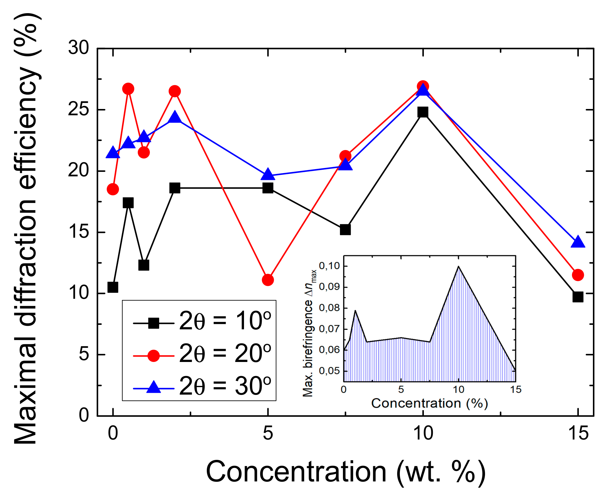
  • TDE (%)—total diffraction efficiency, defined as the sum of the diffraction efficiencies in the +1 and –1 order (DE+1 + DE–1);
  • TPR (%)—transmitted power ratio equal to DE+1 + DE–1 + DE0;
  • DEnorm (%) = 100 × TDE/TPR.
For example, the TPR value for lower concentrations of the goethite nanoparticles (up to 7.5%) is about 80%. This 20% power loss is likely due to reflections from the film surfaces and absorption. At higher concentrations (10% and 15%), however, the TRP drops to 70%, which can be attributed to scattering from the nanoparticles.
The sum of the efficiencies in the two diffraction orders (±1) is tabulated in the column denoted as TDE. It reaches 53% for C = 10%. The ratio between the diffracted power and the total power transmitted through the grating is evaluated by the parameter DEnorm. Considering the reflection and scattering, it can be seen that for the sample with 10% concentration of the NPs, more than 77% of the total transmitted power is redirected in the two diffraction orders.
The AFM scans of the surface topography of the gratings inscribed at recording angle 2θ = 20° are shown in Figure 6. Regular and smooth profiles are observed with spatial period Λexp = 1.29 ± 0.03 µm, which coincides with the theoretically expected value for this recording angle: Λtheor = λrec/(2sinθ) = 1.27 µm. The height of the surface relief (hSRG) obtained from each of these scans is given in the last column of Table 1. As expected, the highest relief is observed for the grating with highest DE, namely the one inscribed in the sample with 10% NP concentration. Still, the relief height does not vary significantly, except for C = 15%, in which a low value of hSRG is measured. The peaks in this case, as seen in Figure 6h, can be explained with the presence of nanoparticles on the surface or close to the surface of the film.
Figure 7 shows the AFM scans of the gratings recorded at the three different beam intersection angles 2θ = 10°, 20°, and 30° in the thin films with NP concentration 10%. Again, uniform fringe profiles were obtained with spatial periods varying in a broad range, from Λ = 0.86 µm (at 2θ = 30°) to Λ = 2.51 µm (at 2θ = 10°). This demonstrates the ease and flexibility in obtaining surface topography with desired characteristics using polarization holography. In the case of the grating with Λ = 0.86 µm, shown in Figure 7c, we noticed that the troughs of the SRG have a different shape than the peaks. As suggested by Moujdi et al. [44], despite that the gradient force acting on the film surface is sinusoidal, the spatial distribution of the displaced volume is Gaussian, regardless of the state of polarization of the interfering beams.
In order to evaluate the influence of the surface relief modulation on the increase of the diffraction efficiency, we have plotted the maximal diffraction efficiency in the +1 order (DE+1max) vs. the height of the surface relief (hSRG), as shown in Figure 8. This approach was recently employed by Falcione et al. [32]. In their study, both recording beams had horizontal polarizations, which results in modulation of the intensity but not in polarization modulation of the interference field. Using a simple model, the authors demonstrated that the increase of the diffraction efficiency was due only to the SRG modulation.
In our recording setup, two beams with left and right circular polarizations were used. The resultant interference field had constant intensity, but strong polarization modulation, as illustrated in the bottom inset of Figure 1. This led to the formation of volume birefringence grating with considerable contribution to the diffraction efficiency. This is clearly seen from the “offset” of the DE data of about 12% for low values of the surface relief height. The effect of the SRG was also well-pronounced and was responsible for the remaining 15% of the efficiency in the cases with significant relief height.
Two possible mechanisms were suggested by our group that can lead to more efficient energy transfer from the recording light to the azopolymer, which results in enhancement of birefringence and higher surface relief in photoanisotropic nanocomposite or hybrid materials. The first is the increase of free volume in the vicinity of the nanoparticles, which leads to higher mobility of the azochromophores [29], and the second is the scattering from the nanoparticles, in which scattered light excites and reorients off-plane chromophores that would otherwise not contribute to the birefringence and surface relief formation [30]. These models are supported by a number of researchers and can also contribute to the increase of both the diffraction efficiency and surface relief modulation in the case of nanocomposite materials. The inorganic nanoparticles incorporated in the polymer act as nanospacers that prevent the closer packing of the polymer chains [45]. For azopolymers, this results in an increase of the free volume and enhanced mobility (photoisomerization, rotation, and reorientation) of the azochromophores [31,32]. The influence of the free volume on the photoinduced birefringence in a guest-host azobenzene-containing polymer has been theoretically and experimentally demonstrated by Dall’Agnol et al. [46]. The scattering caused by the nanoparticles can be beneficial at smaller concentrations when it allows addressing the off-plane chromophores [30]. At higher concentrations, however, the scattering may disrupt the interference pattern of light during the polarization holographic recording, leading to a decrease of DE and the height of SRG. Hence, an optimal concentration of dopant nanoparticles must be found depending on their size, shape, and composition, as well as on the azopolymer optical properties.

4. Conclusions

Two different approaches have been presented in this article to tune the properties of the inscribed polarization holographic gratings. The first is applied at the preparation and deposition stage of the thin film nanocomposite samples. Goethite nanorods with different concentrations have been embedded in the polarization sensitive azopolymer in order to enhance its optical response and the maximal value of the photoinduced birefringence (Δnmax). The second approach is employed at the recording stage. By varying the angle between the two recording beams in the holographic setup, we can obtain polarization holographic gratings with the desired surface topography features (spatial period and height of the SRG), as well as achieve high values of the diffraction efficiency. As demonstrated, surface relief gratings with a broad range of spatial periods from 0.86 to 2.51 µm can be inscribed in the nanocomposite samples combined with relief modulation close to 300 nm. When an optimal concentration of the goethite nanorods is selected, the diffraction efficiency in the +1 order reaches 26% and the total diffraction efficiency in the ±1 orders can be as high as 53%. The dependence of the diffraction efficiency on the nanoparticles’ concentration in the case of goethite nanorods is similar to the birefringence vs. concentration dependence reported by us earlier and shows two maxima—one at low concentrations (0.5–2 wt.%) and one at higher concentrations (10%).

Author Contributions

Conceptualization, L.N. and D.N.; methodology, G.M.; validation, L.N., D.S.S. and D.N.; formal analysis, G.M.; investigation, G.M., V.S. (Velichka Strijkova); resources, V.S. (Verónica Salgueiriño) and G.M.; writing—original draft preparation, L.N.; writing—review and editing, V.S. (Verónica Salgueiriño), D.S.S. and E.S.; visualization, G.M. and N.B.-B.; supervision, L.N. and D.N.; project administration, L.N.; funding acquisition, L.N. and N.B.-B. All authors have read and agreed to the published version of the manuscript.

Funding

This work is supported by the National Science Fund of Bulgaria, grant no. KП-06-H38/15. G.M. is grateful for the financial support from the National Scientific Program for young scientists and postdoctoral fellows, funded by the Bulgarian Ministry of Education and Science (DCM 353/2020). N.B. acknowledges financial support from the National Science Fund of Bulgaria, grant no. M38/2. V.S. acknowledges financial support from the Xunta de Galicia, Regional Government, Spain, grant no. ED431C 2020-06. Research equipment of Distributed Research Infrastructure INFRAMAT, part of Bulgarian National Roadmap for Research Infrastructures, supported by Bulgarian Ministry of Education and Science was used in this investigation.

Data Availability Statement

All data generated or analyzed during this study are included in this published article.

Conflicts of Interest

The authors declare no conflict of interest. The funders had no role in the design of the study; in the collection, analyses, or interpretation of data; in the writing of the manuscript, or in the decision to publish the results.

References

  1. Herzig, H.P.; Dandliker, R. Diffractive components: Holographic optical elements. In Perspectives for Parallel Optical Interconnects; Lalanne, P., Chavel, P., Eds.; Springer: Berlin/Heidelberg, Germany, 1993. [Google Scholar] [CrossRef]
  2. Solano, C. Diffractive elements. In Fundamentals and Basic Optical Instruments; Hernández, D.M., Ed.; CRC Press: Boca Raton, FL, USA, 2017; Volume 1. [Google Scholar] [CrossRef]
  3. Vather, D.; Naydenova, I.; Cody, D.; Zawadzka, M.; Martin, S.; Mihaylova, E.; Curran, S.; Duffy, P.; Portillo, J.; Connell, D.; et al. Serialized holography for brand protection and authentication. Appl. Opt. 2018, 57, E131–E137. [Google Scholar] [CrossRef]
  4. Barachevsky, V.A. The Current Status of the Development of Light-Sensitive Media for Holography (a Review). Opt. Spectrosc. 2018, 124, 373–407. [Google Scholar] [CrossRef]
  5. Nikolova, L.; Ramanujam, P.S. Polarization Holography; Cambridge University Press: Cambridge, UK, 2009. [Google Scholar] [CrossRef]
  6. Kuroda, K.; Matsuhashi, Y.; Fujimura, R.; Shimura, T. Theory of polarization holography. Opt. Rev. 2011, 18, 374–382. [Google Scholar] [CrossRef]
  7. Hong, Y.F.; Kang, G.G.; Zang, J.L.; Fan, F.L.; Liu, Y.; Tan, X.D.; Shimura, T.; Kuroda, K. Investigation of faithful reconstruction in nonparaxial approximation polarization holography. Appl. Opt. 2017, 56, 10024–10029. [Google Scholar] [CrossRef]
  8. Nedelchev, L.; Todorov, T.; Nikolova, L.; Petrova, T.; Tomova, N.; Dragostinova, V. Characteristics of high-efficient polarization holographic gratings. In Proceedings of the SPIE, 11th International School on Quantum Electronics: Laser Physics and Applications, Varna, Bulgaria, 18–22 September 2000; SPIE: Bellingham, WA, USA, 2001; Volume 4397, pp. 338–342. [Google Scholar] [CrossRef]
  9. Martinez-Ponce, G.; Petrova, T.; Tomova, N.; Dragostinova, V.; Todorov, T.; Nikolova, L. Bifocal polarization holographic lens. Opt. Lett. 2004, 29, 1001–1003. [Google Scholar] [CrossRef]
  10. Jashnsaz, H.; Nataj, N.H.; Mohajerani, E.; Khabbazi, A. All-optical switchable holographic Fresnel lens based on azo-dye-doped polymer-dispersed liquid crystals. Appl. Opt. 2011, 50, 4295–4301. [Google Scholar] [CrossRef] [PubMed]
  11. Yeh, H.C.; Kuo, Y.C.; Lin, S.H.; Lin, J.D.; Mo, T.S.; Huang, S.Y. Optically controllable and focus-tunable Fresnel lens in azo-dye-doped liquid crystals using a Sagnac interferometer. Opt. Lett. 2011, 36, 1311–1313. [Google Scholar] [CrossRef] [PubMed]
  12. Wang, J.; Pang, H.; Cao, A.; Zhang, M.; Kan, R.; Hu, S.; Shi, L.; Deng, Q. The Polarization Multiplexing Image with a Single Diffractive Optical Element. IEEE Photonics J. 2017, 9, 7000208. [Google Scholar] [CrossRef]
  13. Ramanujam, P.S.; Dam-Hansen, C.; Berg, R.H.; Hvilsted, S.; Nikolova, L. Polarisation sensitive optical elements in azobenzene polyesters and peptides. Opt. Lasers Eng. 2006, 44, 912–925. [Google Scholar] [CrossRef]
  14. De Sio, L.; Roberts, D.E.; Liao, Z.; Nersisyan, S.; Uskova, O.; Wickboldt, L.; Tabiryan, N.; Steeves, D.M.; Kimball, B.R. Digital polarization holography advancing geometrical phase optics. Opt. Express 2016, 24, 18297–18306. [Google Scholar] [CrossRef]
  15. Yin, K.; Zhan, T.; Xiong, J.; He, Z.; Wu, S.T. Polarization Volume Gratings for Near-Eye Displays and Novel Photonic Devices. Crystals 2020, 10, 561. [Google Scholar] [CrossRef]
  16. Todorov, T.; Nikolova, L.; Tomova, N. Polarization Holography 1: A new high-efficiency organic material with reversible photoinduced birefringence. Appl. Opt. 1984, 23, 4309–4312. [Google Scholar] [CrossRef]
  17. Natansohn, A.; Rochon, P. Photoinduced motions in azo-containing polymers. Chem. Rev. 2002, 102, 4139–4175. [Google Scholar] [CrossRef] [PubMed]
  18. Wang, X. Azo Polymers: Synthesis, Functions and Applications; Springer: Berlin/Heidelberg, Germany, 2017. [Google Scholar] [CrossRef]
  19. Rochon, P.; Batalla, E.; Natansohn, A. Optically induced surface gratings on azoaromatic polymer films. Appl. Phys. Lett. 1995, 66, 136–138. [Google Scholar] [CrossRef]
  20. Kim, D.Y.; Tripathy, S.K.; Li, L.; Kumar, J. Laser-induced holographic surface relief gratings on nonlinear optical polymer films. Appl. Phys. Lett. 1995, 66, 1166–1168. [Google Scholar] [CrossRef] [Green Version]
  21. Viswanathan, N.; Kim, D.; Tripathy, S. Surface relief structures on azo polymer films. J. Mater. Chem. 1999, 9, 1941–1955. [Google Scholar] [CrossRef]
  22. Pagliusi, P.; Audia, B.; Provenzano, C.; Piñol, M.; Oriol, L.; Cipparrone, G. Tunable surface patterning of azopolymer by vectorial holography: The role of photoanisotropies in the driving force. ACS Appl. Mater. Interfaces 2019, 11, 34471–34477. [Google Scholar] [CrossRef]
  23. Nazarova, D.; Nedelchev, L.; Sharlandjiev, P. Surface plasmon-polariton resonances in metal-coated holographic azopolymer gratings. Bulg. Chem. Commun. 2013, 45, 115–118. [Google Scholar]
  24. Berendt, J.; Teixeira, J.M.; García-García, A.; Raposo, M.; Ribeiro, P.A.; Dubowik, J.; Kakazei, G.N.; Schmool, D.S. Tunable magnetic anisotropy in permalloy thin films grown on holographic relief gratings. Appl. Phys. Lett. 2014, 104, 082408. [Google Scholar] [CrossRef]
  25. Jelken, J.; Henkel, C.; Santer, S. Solving an old puzzle: Fine structure of diffraction spots from an azo-polymer surface relief grating. Appl. Phys. B 2019, 125, 218. [Google Scholar] [CrossRef] [Green Version]
  26. Jelken, J.; Brinkjans, M.; Henkel, C.; Santer, S. Rapid Optical Erasure of Surface Relief and Bulk Birefringence Gratings in Azo-Polymer Thin Films. In Proceedings of the SPIE, Photosensitive Materials and their Applications, Online, 6–10 April 2020; SPIE: Bellingham, WA, USA, 2020; Volume 11367, pp. 1–21. [Google Scholar] [CrossRef]
  27. Zhou, J.; Yang, J.; Sun, Y.; Zhang, D.; Shen, J.; Zhang, Q.; Wang, K. Effect of silver nanoparticles on photoinduced reorientation of azo groups in polymer films. Thin Solid Film. 2007, 515, 7242–7246. [Google Scholar] [CrossRef]
  28. Wu, S.; Shen, J.; Huang, J.; Wu, Y.; Zhang, Z.; Hu, Y.; Wu, W.; Huang, W.; Wang, K.; Zhang, Q. Ag nanoparticle/azopolymer nanocomposites: In situ synthesis, microstructure, rewritable optically induced birefringence and optical recording. Polymer 2010, 51, 1395–1403. [Google Scholar] [CrossRef]
  29. Nedelchev, L.; Nazarova, D.; Dragostinova, V.; Karashanova, D. Increase of photoinduced birefringence in a new type of anisotropic nanocomposite: Azopolymer doped with ZnO nanoparticles. Opt. Lett. 2012, 37, 2676–2678. [Google Scholar] [CrossRef]
  30. Nazarova, D.; Nedelchev, L.; Sharlandjiev, P.; Dragostinova, V. Anisotropic hybrid organic/inorganic (azopolymer/SiO2 NP) materials with enhanced photoinduced birefringence. Appl. Opt. 2013, 52, E28–E33. [Google Scholar] [CrossRef] [PubMed]
  31. Berberova, N.; Daskalova, D.; Strijkova, V.; Kostadinova, D.; Nazarova, D.; Nedelchev, L.; Stoykova, E.; Marinova, V.; Chi, C.H.; Lin, S.H. Polarization holographic recording in thin films of pure azopolymer and azopolymer based hybrid materials. Opt. Mater. 2017, 64, 212–216. [Google Scholar] [CrossRef]
  32. Falcione, R.; Roldan, M.V.; Pellegri, N.; Goyanes, S.; Ledesma, S.A.; Capeluto, M.G. Increase of SRG modulation depth in azopolymers-nanoparticles hybrid materials. Opt. Mater. 2021, 115, 111015. [Google Scholar] [CrossRef]
  33. Suzuki, N.; Tomita, Y. Silica-nanoparticle-dispersed methacrylate photopolymers with net diffraction efficiency near 100%. Appl. Opt. 2004, 43, 2125–2129. [Google Scholar] [CrossRef]
  34. Tomita, Y.; Suzuki, N.; Chikama, K. Holographic manipulation of nanoparticle distribution morphology in nanoparticle-dispersed photopolymers. Opt. Lett. 2005, 30, 839–841. [Google Scholar] [CrossRef]
  35. Leite, E.; Naydenova, I.; Mintova, S.; Leclercq, L.; Toal, V. Photopolymerizable nanocomposites for holographic recording and sensor application. Appl. Opt. 2010, 49, 3652–3660. [Google Scholar] [CrossRef] [Green Version]
  36. Nedelchev, L.; Nazarova, D.; Berberova, N.; Mateev, G.; Kostadinova, D.; Mariño-Fernández, R.; Salgueiriño, V.; Schmool, D. Enhanced photoanisotropic response in azopolymer doped with elongated goethite nanoparticles. J. Phys. Conf. Ser. 2016, 700, 012031. [Google Scholar] [CrossRef] [Green Version]
  37. Mariño-Fernández, R.; Masunaga, S.H.; Fontaíña-Troitiño, N.; Morales, M.D.P.; Rivas, J.; Salgueiriño, V. Goethite (α-FeOOH) nanorods as suitable antiferromagnetic substrates. J. Phys. Chem. C 2011, 115, 13991–13999. [Google Scholar] [CrossRef]
  38. Nedelchev, L.; Ivanov, D.; Blagoeva, B.; Nazarova, D. Optical anisotropy induced at five different wavelengths in azopolymer thin films: Kinetics and spectral dependence. J. Photochem. Photobiol. A Chem. 2019, 376, 1–6. [Google Scholar] [CrossRef]
  39. Nedelchev, L.; Ivanov, D.; Berberova, N.; Strijkova, V.; Nazarova, D. Polarization holographic gratings with high diffraction efficiency recorded in azopolymer PAZO. Opt. Quantum Electron. 2018, 50, 212. [Google Scholar] [CrossRef]
  40. Raval, N.; Maheshwari, R.; Kalyane, D.; Youngren-Ortiz, S.R.; Chougule, M.B.; Tekade, R.K. Chapter 10—Importance of Physicochemical Characterization of Nanoparticles in Pharmaceutical Product Development. In Basic Fundamentals of Drug Delivery; Tekade, R., Ed.; Academic Press: Cambridge, MA, USA, 2019; pp. 369–400. [Google Scholar] [CrossRef]
  41. Ho, M.S.; Natansohn, A.; Rochon, P. Azo polymers for reversible optical storage. 7. The effect of the size of the photochromic groups. Macromolecules 1995, 28, 6124–6127. [Google Scholar] [CrossRef]
  42. Nedelchev, L.L.; Matharu, A.S.; Hvilsted, S.; Ramanujam, P.S. Photoinduced anisotropy in a family of amorphous azobenzene polyesters for optical storage. Appl. Opt. 2003, 42, 5918–5927. [Google Scholar] [CrossRef] [PubMed]
  43. Capeluto, M.G.; Falcione, R.; Salvador, R.F.; Eceiza, A.; Goyanes, S.; Ledesma, S.A. Functional surfaces through the creation of adhesion and charged patterns on azopolymer surface relief gratings. Opt. Mater. 2019, 90, 281–288. [Google Scholar] [CrossRef] [Green Version]
  44. Moujdi, S.; Rahmouni, A.; Mahfoud, T.; Nesterenko, D.V.; Halim, M.; Sekkat, Z. Surface relief gratings in azo-polymers revisited. J. Appl. Phys. 2018, 124, 213103. [Google Scholar] [CrossRef]
  45. Merkel, T.C.; Freeman, B.D.; Spontak, R.J.; He, Z.; Pinnau, I.; Meakin, P.; Hill, A.J. Ultrapermeable, reverse-selective nanocomposite membranes. Science 2002, 296, 519–522. [Google Scholar] [CrossRef] [PubMed] [Green Version]
  46. Dall’Agnol, F.F.; Oliveira, O.N., Jr.; Giacometti, J.A. Influence from the free volume on the photoinduced birefringence in azocompound-containing polymers. Macromolecules 2006, 39, 4914–4919. [Google Scholar] [CrossRef]
Figure 1. Optical scheme of the polarization holographic setup. BE: beam expander; HWP: half-wave plate; QWP: quarter-wave plate; PBS: polarization beam splitter; M: mirror; S: sample; PM: power meter. The insets show the light interference field on the sample (bottom) and the different surface grating periods that are obtained by varying the recording angle (right).
Photonics 08 00306 g001
Figure 2. (a) TEM image of the goethite (α-FeOOH) nanorods; (b) absorption coefficient spectrum and chemical structure of the azopolymer PAZO.
Photonics 08 00306 g002
Figure 3. Histogram of the goethite nanorods size distribution based on n = 150 nanoparticles evaluated. (a) NP length distribution; (b) NP width distribution.
Photonics 08 00306 g003
Figure 4. Kinetics of the diffraction efficiency in the +1 order during the holographic recording: (a) for recording angle 2θ = 20° and all samples with C = 0–15%, (b) for concentration of the goethite nanorods C = 10% and recording angles 2θ = 10°, 20°, and 30° (symbols are plotted in (a) at every 500 and in (b) at every 250 data points to distinguish the curves).
Photonics 08 00306 g004
Figure 5. Dependence of the maximal diffraction efficiency in the +1 order (DE+1 max) on the concentration of the goethite nanorods in the thin film samples for all recording angles—2θ = 10°, 20°, and 30°. The inset shows the dependence of the photoinduced birefringence (Δnmax) on the nanorods concentration (adapted from [36]).
Photonics 08 00306 g005
Figure 6. Three-dimensional AFM images of the surface relief gratings, formed at recording angle 2θ = 20° for the following nanoparticles concentrations: (a) C = 0%, (b) C = 0.5%, (c) C = 1%, (d) C = 2%, (e) C = 5%, (f) C = 7.5%, (g) C = 10%, and (h) C = 15%.
Photonics 08 00306 g006
Figure 7. Three-dimensional AFM images of the SRG, inscribed in the thin film sample with NP concentration C = 10% and recording angles (a) 2θ = 10°, (b) 2θ = 20°, and (c) 2θ = 30°.
Photonics 08 00306 g007
Figure 8. Dependence of the diffraction efficiency in the +1 order (DE+1 max) on the height of the surface relief (hSRG). The dashed line illustrates the contribution of the surface relief grating to the diffraction efficiency.
Photonics 08 00306 g008
Table 1. Summary of the diffraction efficiency data for the recording angle 2θ = 20°.
C (%)d (nm)DE+1 max (%)DE+1 (%)DE–1 (%)DE0 (%)TDE (%)TPR (%)DEnorm (%)hSRG (nm)
045018.518.217.147.235.382.542.8170
0.546026.726.524.830.151.381.463.0220
143021.521.019.742.340.783.049.0245
247026.526.324.530.750.881.562.3270
542011.110.89.858.120.678.726.2235
7.541021.220.819.736.340.576.852.7160
1040026.926.626.415.653.068.677.3280
1545011.511.210.348.321.569.830.815
Publisher’s Note: MDPI stays neutral with regard to jurisdictional claims in published maps and institutional affiliations.

