Communication

Waterproof Galvanometer Scanner-Based Handheld Photoacoustic Microscopy Probe for Wide-Field Vasculature Imaging In Vivo

1
School of Electronic and Electrical Engineering, College of IT Engineering, Kyungpook National University, Daegu 41566, Korea
2
Institute of Biomedical Engineering, School of Medicine, Kyungpook National University, Daegu 41566, Korea
3
Department of Bioengineering, University of California, Los Angeles, CA 90095, USA
*
Author to whom correspondence should be addressed.
These authors contributed equally to this work.
Photonics 2021, 8(8), 305; https://doi.org/10.3390/photonics8080305
Submission received: 29 June 2021 / Revised: 27 July 2021 / Accepted: 28 July 2021 / Published: 30 July 2021
(This article belongs to the Special Issue Photoacoustic Imaging and Systems)

Abstract

:
Photoacoustic imaging (PAI) is a hybrid non-invasive imaging technique used to merge high optical contrast and high acoustic resolution in deep tissue. PAI has been extensively developed by utilizing its advantages that include deep imaging depth, high resolution, and label-free imaging. As a representative implementation of PAI, photoacoustic microscopy (PAM) has been used in preclinical and clinical studies for its micron-scale spatial resolution capability with high optical absorption contrast. Several handheld and portable PAM systems have been developed that improve its applicability to several fields, making it versatile. In this study, we developed a laboratory-customized, two-axis, waterproof, galvanometer scanner-based handheld PAM (WP-GVS-HH-PAM), which provides an extended field of view (14.5 × 9 mm2) for wide-range imaging. The fully waterproof handheld probe enables free movement for imaging regardless of sample shape, and volume rate and scanning region are adjustable per experimental conditions. Results of WP-GVS-HH-PAM-based phantom and in vivo imaging of mouse tissues (ear, iris, and brain) confirm the feasibility and applicability of our system as an imaging modality for various biomedical applications.

1. Introduction

Photoacoustic imaging (PAI) is a label-free, non-invasive biomedical imaging technique that has been extensively studied and developed [1,2]. PAI is based on the light-induced ultrasound (US) signal through the photoacoustic (PA) effect (i.e., thermal-elastic expansion) [3]. The optical absorption contrast of target biological tissues determines the intensity of the broadband US waves (i.e., PA waves), which are converted into analog electrical signals by US transducers [4]. Since the degree of scattering of PA signal in biological tissue is comparably less than that of the optical beam, PAI offers improved optical sensitivity with high US resolution compared to other optical imaging modalities in optically turbid media [5]. In addition, using the PA effect, PAI enables the non-invasive characterization of biological and biomedical properties with endogenous and exogenous agents such as metabolism, anatomy information, functional data, and molecular processes [1,6]. Based on the aforementioned distinctive advantages, PAI has been functionally used in various applications including vasculature mapping, assessing hemoglobin oxygen saturation, and blood flow [7,8,9,10].
In particular, photoacoustic microscopy (PAM) is a major implementation of PAI, which provides rich optical absorption with enhanced spatial resolution [11,12]. PAM is largely divided into two different types: optical resolution (OR) and acoustic resolution (AR) PAM, according to the focus type (i.e., optical and acoustic focus, respectively) [13]. OR-PAM provides a high spatial resolution of the subcellular level compared with AR-PAM by tight focusing of the optical excitation beam [14]. Since the ballistic photon regime and scattering limit the penetration depth of OR-PAM, it is required to optimize the spatial resolution and imaging depth because of the trade-off between spatial resolution and depth of focus [15]. With regard to AR-PAM, although the lateral resolution is inferior to that of optical imaging modalities, the penetration depth is enhanced by utilizing comparably weak acoustic scattering in biological tissue than the optical diffusion limit [16]. By utilizing the advantages of each imaging technique, PAM has been investigated for biomedical applications [17,18,19,20].
To expand the applicable conditions and enhance the versatility of PAM compared to the bench-top system, several miniaturized handheld PAM (HH-PAM) have been developed [21,22,23]. To enable fast-scanning with the miniaturized probe, various imaging scanners-based HH-PAM systems were reported (e.g., micro-electro-mechanical system (MEMS) and galvanometer scanner (GVS)). To reduce the volume size of the HH-PAM probe, MEMS mirror has been widely employed following the rapid development of MEMS systems [24,25,26]. Because of the small size of a MEMS mirror, the dimension of the HH-PAM probe is able to be optimized according to the applications. However, the scanning region and scanning stability are relatively small and low compared to GVS. In addition, GVS has been developed as another representative imaging scanner for HH-PAM [27,28,29,30]. As an initial approach to use GVS for the composition of HH-PAM probe, an image-guided fiber bundle-based system was demonstrated [27]. Although the proposed system utilized two-axis GVS for real-time imaging, usage of the fiber bundle, which is costly to use, limits the field of view (FOV) and spatial resolution [27]. In addition, miniaturized HH-PAM probes with GVS and an adjustable light focus were developed for in vivo imaging [28,29,30]. However, limitations, including the small imaging range [28], low axial resolution due to the use of a cylindrically focused acoustic transducer, and relatively slow scanning speed [29,30] remained.
In this study, we present a two-axis waterproof GVS-based HH-PAM (WP-GVS-HH-PAM) probe, which provides an extensive FOV for wide-range in vivo experiments. The proposed system is customized to enable portable PA imaging based on the previously reported bench-top type two-axis GVS PAM [31]. To improve the signal-to-noise ratio (SNR) and enable limitless movement of the probe, WP-GVS-HH-PAM was comprised of an opto-acoustic combiner (for coaxial and confocal alignment of the optical beam and acoustic signal) and a laboratory-made two-axis WP-GVS for wide FOV. The system performance was quantitatively evaluated by resolution (spatial and axial), penetration depth, scanning range, and SNR. In addition, the applicability of WP-GVS-HH-PAM for biomedical fields was demonstrated by phantom and mouse in vivo imaging (ear, iris, and brain). The obtained results present the feasibility of WP-GVS-HH-PAM as an imaging modality in various biomedical applications requiring a wide scanning region and high spatial resolution.

2. Materials and Methods

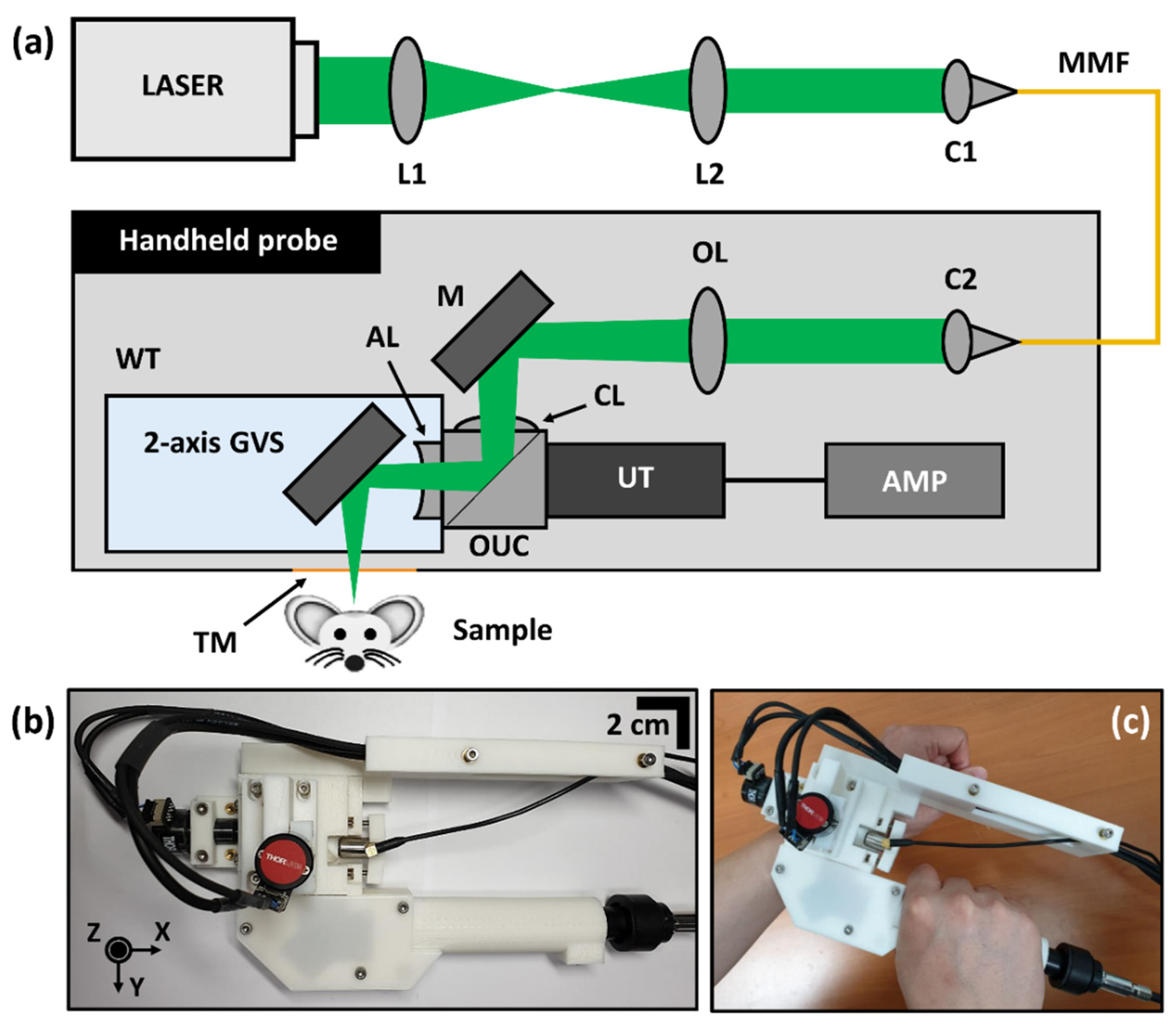
2.1. System Configuration of WP-GVS-HH-PAM

Figure 1 demonstrates the optical configuration and photograph of the developed WP-GVS-HH-PAM system. A Q-switched diode-pumped laser (SPOT-10-200-532, Elforlight Ltd., Daventry, UK), whose wavelength is 532 nm with tunable repetition rates from 1 to 50 kHz, was used for PA imaging (Figure 1a). L1 (AC254-075-A, Thorlabs Inc., Newton, NJ, USA) and L2 (AC254-030-A, Thorlabs Inc., USA) were used to reduce the size of beam diameter with collimation. In addition, the collimated beam was transmitted by C1 (TC12FC-532, Thorlabs Inc., USA) to multi-mode fiber (M64L02, Thorlabs Inc., USA) for beam delivery. At the end of the multi-mode fiber, C2 (TC25FC-532, Thorlabs Inc., USA) transferred the beam with an enlarged diameter than was larger than the incident beam of C1. The output beam from C2 was focused by an objective lens (AC254-100-AB, Thorlabs Inc., USA) and passed to a two-axis GVS through the laboratory-made opto-acoustic beam combiner. The custom opto-acoustic beam combiner consisted of an uncoated BK7 prism (PS910, Thorlabs Inc., USA), a dielectric-coated prism (MRA10-E02, Thorlabs Inc., USA), a correction lens with a 54 mm focal length (67–147, Edmund Optics Inc., Barrington, NJ, USA), and an acoustic lens with a 27 mm acoustic focal length (45–384, Edmund Optics Inc., USA). To minimize attenuation of the optical beam and acoustic signal in the opto-acoustic beam combiner, optical adhesive was applied to each junction of each component (37–322, Edmund Optics Inc., USA). The correction lens corrects optical aberration caused by the acoustic lens, and a dielectric coated film between two prisms was used to reflect the optical beam and transmit the acoustic signal. To implement the fully waterproof WP-GVS-HH-PAM probe, we modified the previously presented two-axis waterproof GVS with a 3D printing-based customized probe [31]. This fully waterproof probe enables free movement of WP-GVS-HH-PAM for wide-range scanning. The beam reflected by two-axis GVS (GVS102, Thorlabs Inc., USA) illuminates the sample through a window, which is sealed with a polyethylene membrane for transmission of the optical beam and PA signal. A photograph of the developed WP-GVS-HH-PAM probe is shown in Figure 1b.
As an aspect of PA signal processing, an ultrasound transducer (V214-BB-RM, Olympus NDT, Shinjuku, Tokyo, Japan) with a 50 MHz center frequency was utilized for converting the PA wave into electrical signals. The detected electrical signal was amplified by serially connecting two pre-amplifiers (ZFL-500LN+, Mini-Circuits, Brooklyn, NY, USA) with 52 dB gain. The amplified signal was transformed into a 12-bit digital signal by a digitizer (ATS9350, Alazar Technologies Inc., Pointe-Claire, QC, Canada) with a 500 MHz sampling rate and a 250 MHz full-power bandwidth. To precisely synchronize the scanning speed with data acquisition, a data acquisition board (DAQ, NI PCIe-6323, National Instrument Corporation, Austin, TX, USA) was implemented. At the rising edge of the main trigger from the DAQ, laser pulse generation, scanning of fast-axis scanner, and digitizer acquisition were simultaneously started, and PA imaging was successively conducted. In addition, the fast-axis of GVS was operated with a triangular waveform, which enhances the stability and durability of the scanner. Scanning was started according to the rising edge of the main trigger.

2.2. Animal Experiment Protocol

For in-vivo animal experiments, all experimental procedures were performed following the guidelines of the Institutional Animal Care and Use Committee (IACUC) of Kyungpook National University (No. KNU-2020-0025). The illumination laser beam for the tissues (mouse ear, iris, and brain) adhered to the American Standard Institute safety limit of 532 nm wavelength. A normal healthy Balb/c mouse (male, 12 weeks old) was used for in vivo study. We used an isoflurane machine to anesthetize the mouse with 1 L/min of oxygen and 0.75% isoflurane before PA imaging. An anesthetized mouse was placed on the imaging stage with an electronic heating pad to maintain the body temperature during the experiment and the state was checked by monitoring the movement of hands and feet. Ultrasound gel (Power sonic, Tamin Inc., Bloomfield, KY, USA) was applied to the region of interest (ROI) as an acoustic impedance-matching material between mouse and probe membrane. After the experiments, the mouse was sacrificed according to the approved techniques from the IACUC of KNU.

3. Results

3.1. Performance Evaluation of WP-GVS-HH-PAM

To quantitatively evaluate the system performance of the proposed WP-GVS-HH-PAM, we obtained both lateral and axial resolutions (Figure 2a–d). To measure the spatial resolution, a sharp blade was used to obtain the PA maximum amplitude projection (MAP) image (Figure 2a). Based on this result, extracted PA intensities from the selected line, along with the x-direction, were used to calculate the lateral resolution. In accordance with the extracted intensity values from the white dashed line (a–b) in Figure 2a, the obtained spatial resolution was 11.5 μm (Figure 2b), which was fitted using an edge-spread function and a line-spread function (LSF). To minimize the line-edge roughness of the sharp blade, we averaged 50 A-lines centered on line a–b. In addition, to measure the axial resolution, we imaged a carbon fiber of 7 μm diameter (Carbon Fiber Yarn, Zhongfu shenying carbon fiber Co.,Ltd, Lianyungang city, China) and extracted the PA intensities along with the depth direction in the B-scan image (white dashed line of c–d in Figure 2c). According to the full width at half maximum of LSF fitting from the Gaussian profile in Figure 2d, the measured axial resolution was 31.3 μm, which is close to the theoretical value of 33 μm. To reduce the oscillation effect and so obtain the time-resolved A-line signal, we averaged 50 B-scan images for the selected center position of cross-section images. In addition, as an aspect of the envelope-fitting function to minimize the time oscillatory problem, we applied the Hilbert transform-based ultrasound envelope detection method in our PA signal acquisition software. The reason for the occurrent difference between the theoretical value and measured one is the reduced time variant effect from applied averaging. The theoretical value was primarily determined by the specification of the ultrasound transducer, whose −6 dB bandwidth was 40.63 MHz with a 50 MHz center frequency, while the velocity of sound was 1540 m/s. The obtained lateral and axial resolutions were sufficient for vascular mapping in small animals in vivo, whose diameter varied from 4 to 50 μm according to the type of vessel [32,33].
To measure the effective imaging depth of WP-GVS-HH-PAM in the biological tissue, we prepared a black needle inserted at chicken breast tissue (Figure 2e). The black needle was diagonally inserted to generate the PA signal. The PA signals were detected well regardless of the depth of the needle from the surface of the chicken breast tissue (Figure 2f). The measured imaging depth in biological tissue was 788 μm, which was in the range of 128 pixels in the depth direction (6.16 μm per single pixel). Because a two-axis GVS was implemented in the probe, the scanning range varied from micro-scale (142 μm at 0.1 V of galvanometer scanner) to 14.5 × 9 mm2 (fast axis × slow axis) according to the voltage value applied to the scanners. Therefore, the possible maximum scanning volume was 14.5 × 9 × 0.78 mm3 (x × y × z). The upper limit in the depth direction is determined by the acoustic signal transmission time and acquisition rate of the digitizer. Moreover, the axial range was selected by the depth of focus range. In addition, with regard to the scanning speed, the B-scan (800 (fast-axis) × 512 (depth-direction)) and volumetric images (800 (fast-axis) × 800 (slow-axis) × 512 (depth-direction)) were obtained in 0.04 s and 32 s, respectively. Moreover, the SNR of our system was measured using carbon fiber for axial resolution measurement. The obtained averaged SNR is 37.8 dB and this value is sufficient to image a single red blood cell [34].

3.2. Phantom Images Using WP-GVS-HH-PAM

To verify the applicability of the developed system to in vivo imaging of microvasculature, we imaged carbon-fiber networks and a leaf skeleton target as vessel-mimicking phantom samples (Figure 3). Each phantom sample was used to demonstrate the versatility for imaging a narrow area with high-resolution (carbon fiber networks) and scanning a wide region (leaf skeleton target), respectively. We minimized the laser power enough to measure the structure since both phantom samples easily burn due to the high absorption rate. Similar to that done with carbon fiber networks, to prepare a bunch of fibers (7 μm diameter), we randomly placed them on the slide glass with distilled water and covered them with a cover glass. The role of the cover glass was maintaining the sample position for the microscope and PAM imaging. Although signal attenuation through cover glass is occurred, we nonetheless used it for exact matching of the sample position. The scanning range for the carbon fiber network was 1.7 × 1.4 mm for the ROI (red square in Figure 3a; this is a photograph obtained using a microscope). Figure 3c is the measured PA MAP image of ROI, which clearly identifies not only single fibers but also overlapped regions. In addition, we captured the PA MAP image of the leaf phantom shown in Figure 3d for the ROI (red square in Figure 3b), wherein the scanning range was 11.6 × 6.1 mm to cover the wide region. PA MAP yielded structural information identical to the photograph (Figure 3b) regardless of the thickness of the leaf veins. Based on the imaging results of a vessel-mimicking sample, the system was capable of in vivo imaging of microvasculature in a small animal.

3.3. WP-GVS-HH-PAM for In Vivo Experiments with a Mouse

As an in vivo experiment, the microvasculature of mouse ear, iris, and brain were imaged using WP-GVS-HH-PAM. The intensity-based PA MAP images captured for each target tissue are shown in Figure 4. The obtained image of the vasculature map in the mouse ear (Figure 4a) demonstrates the micro-vessel networks including single capillaries, an artery, and a vein. The FOV for imaging a mouse ear was 9.0 × 8.2 mm, which was sufficient to obtain complete structural information of the ear with a single scan. In addition, we captured the PA MAP image of the iris (Figure 4b) with a FOV of 3.1 × 2.6 mm. The resulting image showed the microvasculature of the iris; we have adjusted the focus by regulating the position of the objective lens to image the lateral region for this image. The PA MAP image of the mouse brain under an intact skull (Figure 4c) was also obtained. The FOV was 10.5 × 7.0 mm, and the distinctive blood vascular features, which are indicated as white arrow (e.g., sagittal sinus and coronal suture) were visualized. In addition, as an aspect of depth-encoded PA MAP images to provide 3D volume data-based quantitative information, the depth profile along with the z-axis direction was applied to in vivo PA images, as shown in Figure 4d–f. By using the wide FOV of WP-GVS-HH-PAM, we were able to measure the whole range of each target tissue without applying an additional imaging technique, such as a linear stage, to overcome the limited scanning range.

4. Discussions

Here, we presented a HH-PAM probe with an extended FOV for wide-range scanning regardless of sample shape. The previously presented GVS-based HH-PAM probe has a limited FOV, caused by the clear aperture or usable region of other optical components used after GVS (e.g., fiber bundles and objective lens) [27,28]. In contrast, the scanning range of the proposed system was relatively enlarged, given that the two-axis WP-GVS was located at the terminal end of the HH probe. Furthermore, the presented system provides comparably improved axial resolution, from 90 μm to 31.3 μm, compared to cylindrically-focused acoustic transducer-based systems [29,30]. In addition, although the MEMS-based HH-PAM system provides an enhanced scanning rate compared to GVS and miniaturized probe volume size, the FOV was limited because of the small size of the MEMS mirror. WP-GVS-HH-PAM, however, can capture a wide area in a single scan, owing to the relatively large scanning angle of the GVS mirror (±25°) compared to the MEMS scanner (±18° for fast-axis and ±11° for slow-axis) [21]. In addition, through triangular wave signal-based GVS scanning, the durability of the developed scanner is enhanced, and a high sensitivity for the scanning position was maintained even at high-speed scanning. WP-GVS-HH-PAM advances the previously reported system [31] as an aspect of the movement of the imaging probe, which enhances the applicability of PA imaging systems. By applying fiber coupling through the implementation of the multimode fiber and modified, 3D modeling-based probe construction, WP-GVS-HH-PAM provides unrestricted movement of the probe motion and enhances the convenience of PA imaging.
With regard to resolution, the measured lateral resolution of the proposed system was 11.5 μm. Although the obtained value was sufficient for in vivo microvascular mapping of small animals, the lateral resolution of the system can be further improved by adding a lens pair (i.e., beam expander) before the objective lens. In addition, the scanning time for volumetric imaging using WP-GVS-HH-PAM was 32 s for an 800 × 800 × 512 pixel image. This time can be adjusted by the number of pixels according to the experimental requirements. The scanning speed and the sensitivity of WP-GVS-HH-PAM for in vivo imaging can be improved by using another laser source with an enhanced pulse-repetition rate and high-power light. Moreover, the FOV can also be adjusted following the ROI from a micrometer scale to up to 14.5 × 9 mm2, which is sufficient to measure the whole region of the mouse brain.

5. Conclusions

In conclusion, we demonstrated the WP-GVS-HH-PAM with a laboratory customized two-axis WP-GVS that provides an extensive scanning range for a wide range in vivo 3D imaging. The developed HH-probe consisted of a two-axis WP-GVS for wide scanning and an opto-acoustic combiner for coaxial and confocal alignment of the optical beam and acoustic signal. Compared to the conventional HH-PAM systems, our proposed WP-GVS-HH-PAM provides an extended FOV (from micro-scale (142 μm at 0.1 V of galvanometer scanner) to 14.5 × 9 mm2) for in vivo imaging. The spatial and axial resolutions were 11.5 μm and 31.3 μm, respectively, which are sufficient for vascular mapping. We quantitatively evaluated the system performance using vessel-mimicking phantom samples (carbon fiber networks and leaf skeleton) and in vivo imaging in a small animal (mouse ear, iris, and brain). The obtained results of the implemented WP-GVS-HH-PAM demonstrate the feasibility of capturing a microvascular map of several animal tissues. Hence, the proposed system shows promising results encouraging the applications of HH-PAM to various biomedical applications including preclinical and clinical research with small animals in vivo.

Author Contributions

Conceptualization, M.J. and J.K.; methodology, D.S. and S.H.; software, S.H.; validation, D.S., J.L. (Jaeyul Lee) and Y.K.; formal analysis, D.S. and S.H; investigation, Y.K., E.L. and J.L. (Junsoo Lee); resources, M.J. and J.K.; data curation, D.S., S.H., Y.K. and E.L.; writing—original draft preparation, D.S.; writing—review and editing, S.H. and J.L. (Jaeyul Lee); visualization, D.S., S.H. and E.L.; supervision, M.J. and J.K.; project administration, M.J.; funding acquisition, M.J. and J.K. All authors have read and agreed to the published version of the manuscript.

Funding

This work was supported by LG Yonam Foundation (of Korea) and also supported by Basic Science Research Program through the National Research Foundation of Korea (NRF) funded by the Ministry of Education (2020R1I1A1A01072399), and supported by Basic Science Research Program through the National Research Foundation of Korea (NRF) funded by the Ministry of Education (2018R1D1A1B07043340).

Institutional Review Board Statement

The study was conducted according to the guidelines of the Declaration of Helsinki, and approved by the Institutional Review Board of the Institutional Animal and Human Care and Use Committee of Kyungpook National University (No. KNU-2020-0025).

Informed Consent Statement

Not applicable.

Data Availability Statement

The data presented in this study are available on request from the corresponding author.

Conflicts of Interest

The authors declare no conflict of interest.

References

  1. Wang, L.V.; Hu, S. Photoacoustic tomography: In vivo imaging from organelles to organs. Science 2012, 335, 1458–1462. [Google Scholar] [CrossRef] [PubMed] [Green Version]
  2. Xia, J.; Yao, J.; Wang, L.V. Photoacoustic tomography: Principles and advances. Electromagn. Waves (Camb. Mass) 2014, 147, 1. [Google Scholar] [CrossRef] [PubMed] [Green Version]
  3. Wang, L.V.; Yao, J. A practical guide to photoacoustic tomography in the life sciences. Nat. Methods 2016, 13, 627. [Google Scholar] [CrossRef]
  4. Jeon, M.; Kim, C. Multimodal photoacoustic tomography. IEEE Trans. Multimed. 2013, 15, 975–982. [Google Scholar] [CrossRef]
  5. Jeon, M.; Kim, J.; Kim, C. Multiplane spectroscopic whole-body photoacoustic imaging of small animals in vivo. Med. Biol. Eng. Comput. 2016, 54, 283–294. [Google Scholar] [CrossRef]
  6. Zhang, Y.; Jeon, M.; Rich, L.J.; Hong, H.; Geng, J.; Zhang, Y.; Shi, S.; Barnhart, T.E.; Alexandridis, P.; Huizinga, J.D. Non-invasive multimodal functional imaging of the intestine with frozen micellar naphthalocyanines. Nat. Nanotechnol. 2014, 9, 631–638. [Google Scholar] [CrossRef]
  7. Li, C.; Aguirre, A.; Gamelin, J.K.; Maurudis, A.; Zhu, Q.; Wang, L.V. Real-time photoacoustic tomography of cortical hemodynamics in small animals. J. Biomed. Opt. 2010, 15, 010509. [Google Scholar] [CrossRef] [PubMed]
  8. Xia, J.; Wang, L.V. Small-animal whole-body photoacoustic tomography: A review. IEEE Trans. Biomed. Eng. 2013, 61, 1380–1389. [Google Scholar] [CrossRef] [Green Version]
  9. Upputuri, P.K.; Pramanik, M. Recent advances toward preclinical and clinical translation of photoacoustic tomography: A review. J. Biomed. Opt. 2016, 22, 041006. [Google Scholar] [CrossRef]
  10. Upputuri, P.K.; Pramanik, M. Performance characterization of low-cost, high-speed, portable pulsed laser diode photoacoustic tomography (PLD-PAT) system. Biomed. Opt. Express 2015, 6, 4118–4129. [Google Scholar] [CrossRef] [Green Version]
  11. Yao, J.; Wang, L.V. Photoacoustic microscopy. Laser Photonics Rev. 2013, 7, 758–778. [Google Scholar] [CrossRef]
  12. Jeon, S.; Kim, J.; Lee, D.; Baik, J.W.; Kim, C. Review on practical photoacoustic microscopy. Photoacoustics 2019, 15, 100141. [Google Scholar] [CrossRef]
  13. Kim, C.; Park, S.-J.; Kim, J.; Lee, S.; Lee, C.; Jeon, M.; Kim, J.; Oh, K.K. Objective-free optical-resolution photoacoustic microscopy. J. Biomed. Opt. 2012, 18, 010501. [Google Scholar] [CrossRef] [Green Version]
  14. Maslov, K.; Zhang, H.F.; Hu, S.; Wang, L.V. Optical-resolution photoacoustic microscopy for in vivo imaging of single capillaries. Opt. Lett. 2008, 33, 929–931. [Google Scholar] [CrossRef] [PubMed]
  15. Park, S.; Lee, C.; Kim, J.; Kim, C. Acoustic resolution photoacoustic microscopy. Biomed. Eng. Lett. 2014, 4, 213–222. [Google Scholar] [CrossRef]
  16. Zhang, H.F.; Maslov, K.; Stoica, G.; Wang, L.V. Functional photoacoustic microscopy for high-resolution and noninvasive in vivo imaging. Nat. Biotechnol. 2006, 24, 848–851. [Google Scholar] [CrossRef] [PubMed]
  17. Wong, T.T.; Zhang, R.; Hai, P.; Zhang, C.; Pleitez, M.A.; Aft, R.L.; Novack, D.V.; Wang, L.V. Fast label-free multilayered histology-like imaging of human breast cancer by photoacoustic microscopy. Sci. Adv. 2017, 3, e1602168. [Google Scholar] [CrossRef] [PubMed] [Green Version]
  18. Shi, J.; Wong, T.T.; He, Y.; Li, L.; Zhang, R.; Yung, C.S.; Hwang, J.; Maslov, K.; Wang, L.V. High-resolution, high-contrast mid-infrared imaging of fresh biological samples with ultraviolet-localized photoacoustic microscopy. Nat. Photonics 2019, 13, 609–615. [Google Scholar] [CrossRef] [PubMed]
  19. Cao, R.; Li, J.; Ning, B.; Sun, N.; Wang, T.; Zuo, Z.; Hu, S. Functional and oxygen-metabolic photoacoustic microscopy of the awake mouse brain. Neuroimage 2017, 150, 77–87. [Google Scholar] [CrossRef] [PubMed] [Green Version]
  20. Lan, B.; Liu, W.; Wang, Y.-C.; Shi, J.; Li, Y.; Xu, S.; Sheng, H.; Zhou, Q.; Zou, J.; Hoffmann, U. High-speed widefield photoacoustic microscopy of small-animal hemodynamics. Biomed. Opt. Express 2018, 9, 4689–4701. [Google Scholar] [CrossRef]
  21. Park, K.; Kim, J.Y.; Lee, C.; Jeon, S.; Lim, G.; Kim, C. Handheld photoacoustic microscopy probe. Sci. Rep. 2017, 7, 1–15. [Google Scholar] [CrossRef] [PubMed]
  22. Lin, L.; Zhang, P.; Xu, S.; Shi, J.; Li, L.; Yao, J.; Wang, L.; Zou, J.; Wang, L.V. Handheld optical-resolution photoacoustic microscopy. J. Biomed. Opt. 2016, 22, 041002. [Google Scholar] [CrossRef]
  23. Xu, S.; Huang, C.-H.; Zou, J. Microfabricated water-immersible scanning mirror with a small form factor for handheld ultrasound and photoacoustic microscopy. J. Micro/Nanolithography MEMS MOEMS 2015, 14, 035004. [Google Scholar] [CrossRef]
  24. Chen, Q.; Guo, H.; Jin, T.; Qi, W.; Xie, H.; Xi, L. Ultracompact high-resolution photoacoustic microscopy. Opt. Lett. 2018, 43, 1615–1618. [Google Scholar] [CrossRef] [PubMed] [Green Version]
  25. Guo, H.; Song, C.; Xie, H.; Xi, L. Photoacoustic endomicroscopy based on a MEMS scanning mirror. Opt. Lett. 2017, 42, 4615–4618. [Google Scholar] [CrossRef] [PubMed]
  26. Qi, W.; Chen, Q.; Guo, H.; Xie, H.; Xi, L. Miniaturized optical resolution photoacoustic microscope based on a microelectromechanical systems scanning mirror. Micromachines 2018, 9, 288. [Google Scholar] [CrossRef] [Green Version]
  27. Hajireza, P.; Shi, W.; Zemp, R.J. Real-time handheld optical-resolution photoacoustic microscopy. Opt. Express 2011, 19, 20097–20102. [Google Scholar] [CrossRef]
  28. Zhang, W.; Ma, H.; Cheng, Z.; Wang, Z.; Zhang, L.; Yang, S. Miniaturized photoacoustic probe for in vivo imaging of subcutaneous microvessels within human skin. Quant. Imaging Med. Surg. 2019, 9, 807. [Google Scholar] [CrossRef]
  29. Jin, T.; Guo, H.; Jiang, H.; Ke, B.; Xi, L. Portable optical resolution photoacoustic microscopy (pORPAM) for human oral imaging. Opt. Lett. 2017, 42, 4434–4437. [Google Scholar] [CrossRef] [PubMed]
  30. Jin, T.; Guo, H.; Yao, L.; Xie, H.; Jiang, H.; Xi, L. Portable optical-resolution photoacoustic microscopy for volumetric imaging of multiscale organisms. J. Biophotonics 2018, 11, e201700250. [Google Scholar] [CrossRef]
  31. Lee, J.; Han, S.; Seong, D.; Lee, J.; Park, S.; Wijesinghe, R.E.; Jeon, M.; Kim, J. Fully waterproof two-axis galvanometer scanner for enhanced wide-field optical-resolution photoacoustic microscopy. Opt. Lett. 2020, 45, 865–868. [Google Scholar] [CrossRef]
  32. Tsai, P.S.; Kaufhold, J.P.; Blinder, P.; Friedman, B.; Drew, P.J.; Karten, H.J.; Lyden, P.D.; Kleinfeld, D. Correlations of neuronal and microvascular densities in murine cortex revealed by direct counting and colocalization of nuclei and vessels. J. Neurosci. 2009, 29, 14553–14570. [Google Scholar] [CrossRef] [PubMed] [Green Version]
  33. Joseph, A.; Guevara-Torres, A.; Schallek, J. Imaging single-cell blood flow in the smallest to largest vessels in the living retina. Elife 2019, 8, e45077. [Google Scholar] [CrossRef] [PubMed]
  34. Hu, S.; Maslov, K.; Wang, L.V. Second-generation optical-resolution photoacoustic microscopy with improved sensitivity and speed. Opt. Lett. 2011, 36, 1134–1136. [Google Scholar] [CrossRef] [PubMed] [Green Version]
Figure 1. Schematic representation of WP-GVS-HH-PAM. (a) Optical configuration of the system. (b) A photograph of WP-GVS-HH-PAM probe. (c) utilizing WP-WGS-HH-PAM probe for PA imaging. AL, acoustic lens; AMP, amplifier; C, collimator; CL, correction lens; L, lens; M, mirror; MMF, multi-mode fiber; OL, objective lens; OUC, opto-acoustic combiner; TM, transparent membrane; UT, ultrasound transducer; WT, water tank.
Photonics 08 00305 g001
Figure 2. Quantitative evaluations of WP-GVS-HH-PAM performance. (a) PA MAP image of a sharp blade. (b) ESF and LSF fitting graph of the PA MAP data across the line a–b in (a). (c) PA B-scan image of a 7 μm diameter carbon fiber. (d) LSF fitting graph with Gaussian profiling of the PA data across the line c−d in (c). (e) Photograph of the prepared chicken breast tissue inserted with the black need for measuring an imaging depth. (f) PA B-scan image for imaging depth measurement obtained with the prepared sample in (e). ESF, edge spread function; LSF, line spread function; MAP, maximum amplitude projection.
Photonics 08 00305 g002
Figure 3. Photographs and PA MAP images of carbon fiber networks and a leaf skeleton target. (a) Magnified photograph of carbon fiber networks. (b) Magnified photograph of leaf skeleton target. (c,d) PA MAP images of the region in (a,b), respectively. MAP, maximum amplitude projection.
Photonics 08 00305 g003
Figure 4. In vivo PA MAP images of micro-vascular maps using WP-GVS-HH-PAM in mouse ear, iris, and brain, respectively. (ac) PA signal intensity-based MAP images. (df) Depth-encoded PA MAP images.
Photonics 08 00305 g004
Publisher’s Note: MDPI stays neutral with regard to jurisdictional claims in published maps and institutional affiliations.

