Article

Optical See-through 2D/3D Compatible Display Using Variable-Focus Lens and Multiplexed Holographic Optical Elements

1
College of Electronics and Information Engineering, Sichuan University, Chengdu 610065, China
2
School of Instrumentation Science and Optoelectronics Engineering, Beihang University, Beijing 100191, China
*
Author to whom correspondence should be addressed.
Photonics 2021, 8(8), 297; https://doi.org/10.3390/photonics8080297
Submission received: 28 June 2021 / Revised: 21 July 2021 / Accepted: 23 July 2021 / Published: 27 July 2021
(This article belongs to the Special Issue Smart Pixels and Imaging)

Abstract

:
An optical see-through two-dimensional (2D)/three-dimensional (3D) compatible display using variable-focus lens and multiplexed holographic optical elements (MHOE) is presented. It mainly consists of a MHOE, a variable-focus lens and a projection display device. The customized MHOE, by using the angular multiplexing technology of volumetric holographic grating, records the scattering wavefront and spherical wavefront array required for 2D/3D compatible display. In particular, we proposed a feasible method to switch the 2D and 3D display modes by using a variable-focus lens in the reconstruction process. The proposed system solves the problem of bulky volume, and makes the MHOE more efficient to use. Based on the requirements of 2D and 3D displays, we calculated the liquid pumping volume of the variable-focus lens under two kinds of diopters.

1. Introduction

Augmented reality (AR) is a technology which allows computer generated virtual imagery to exactly overlay physical objects [1,2]. AR display mainly includes optical see-through type [3], video see-through type [4] and reflection type [5,6] display devices. At present, the optical see-through display device has become the mainstream technical solution, because it allows the user to directly watch the real environment light through an image combiner, and improves the user’s perception of the real world. As a kind of true three-dimensional (3D) display technology, integral imaging has a compact structure and can provide various physiological depth cues [7,8]. It is conductive for the natural integration of virtual 3D images and real scenes, and is suitable to be integrated into AR display devices [9,10]. However, due to optical modulation of the lens array, integral imaging is not compatible with two-dimensional (2D) display. Although 3D display can provide depth information that is absent in 2D display, the current 3D resolution is severely degraded. The 2D display has the advantage of high resolution and large viewing angle, but it can’t replace 3D display. Therefore, some researchers have proposed 2D/3D compatible displays, such as switching backlight units by using polarized pinhole array [11,12] and polymer dispersed liquid crystal (PDLC) [13], or using dynamic parallax grating technology [14], but these technologies cannot be applied to optical see-through AR display devices.
The technology that is key to realizing optical see-through AR display is the image combiner that overlaps the virtual images and the real scenes together. The image combiner can be further divided into two categories: reflection-type devices [15,16] and diffraction-type devices [17,18]. Compared with reflection-type devices, the diffraction-type devices have many advantages, such as unique angle selectivity and wavelength selectivity and flexibility of design, as well as high diffraction efficiency and transparency. It can replace one or several optical elements in the system and is an ideal image combiner [19]. Yeom et al. proposed a 2D/3D convertible projection system using see-through integral imaging based on HOE. The use of prism reduced the number of projectors and enabled a compact form factor, but the utilization of the HOE was only 50%, that is, one half of the HOE was used for 2D display and the other half for 3D display [20]. Chou. et al. proposed a 2D/3D hybrid integral imaging display based on a liquid crystal micro-lens array (LCMLA), in which the LCMLA has the focusing effect or no optical effect determined by the polarization state of the incident light. Therefore, the system added devices such as twisted nematic cell and polarizer to control the polarization state, and increased the redundancy [21]. In our previous work, we proposed attaching a PDLC film to the lens array HOE to constitute a 2D/3D projection screen. The lens array HOE and PDLC film were used to realize integral imaging 3D display and 2D display, respectively. However, the PDLC film degraded the transparency of the system, and the optical see-through properties could not be achieved in 2D mode [22].
In this paper, we propose an optical see-through 2D/3D compatible display by using variable-focus lens and multiplexed holographic optical elements (MHOE). Based on angular multiplexing technology, the MHOE records the scattering wavefront of a diffuser for 2D display and the spherical wavefront array of micro-lens array (MLA) for 3D display. The incident angles of the projected angles vary with the changes in the variable-focus lens to meet the two Bragg diffraction conditions of 2D and 3D displays. Therefore, our approach does not require polarization devices and reduces the systematic complexity, enhances the effective utilization of MHOE and maintains optical see-through properties for both 2D and 3D displays, all of which are highly beneficial for AR applications.

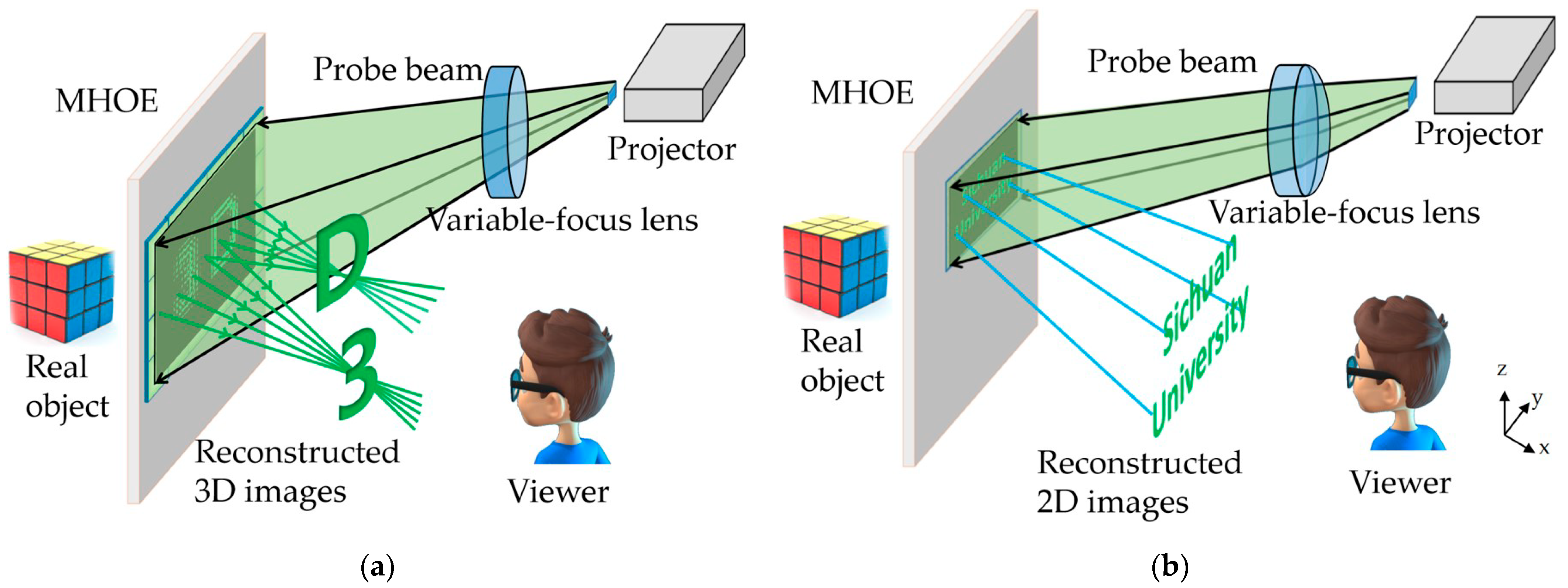
2. Structure and Principle

Figure 1 shows the structure of our proposed optical see-through 2D/3D compatible display system. It is mainly composed of a MHOE, a variable-focus lens and a projector. Essentially, the MHOE is a volumetric holographic grating. The scattering wavefront of a diffuser and the spherical wavefront array of MLA are recorded on the single volumetric holographic grating by two-step recording with angular multiplexing technology. The variable-focus lens has two optical states of diopter φ1 and φ2, and it modulates the light transmitted by the projector respectively to meet the two Bragg diffraction conditions of MHOE.
In Figure 1a, the probe beam from the projector contains the amplitude information of elemental image array, and illuminates the MHOE after passing through the variable-focus lens with the diopter of φ1. Then, the MHOE’s Bragg diffraction condition 1 is satisfied, and the spherical wavefront array is diffracted out. The elemental image aligns with the element of MHOE to reconstruct the 3D image based on the theory of integral imaging. In Figure 1b, the probe beam from the projector contains the 2D image, and illuminates the MHOE after passing through the variable-focus lens with the diopter of φ2. At this time, the MHOE’s Bragg diffraction condition 2 is satisfied, and the scattering wavefront is diffracted out to achieve 2D display. The light from the real scene whose wavelengths and incident angles don’t match the Bragg diffraction conditions, directly passes through the MHOE. Hence, the system shows good optical see-through properties.
In the reconstruction process, the variable-focus lens is the key component that plays a role in the angle selectivity of MHOE. It can accurately change the incident angles of the reconstructed beam under different diopter conditions in order to meet the Bragg matching angles. In the 3D mode, the divergent angle of projected beam is 2U1, and it doesn’t change after passing through the variable-focus lens with the diopter of φ1 = 0D. The conical beam still maintains the divergent angle of 2U1 when it arrives at the MHOE, the incident angles of the two boundary beams are θl1 and θr1, respectively, as shown in Figure 2a. The θl1 and θr1 can be expressed as
θ l 1 = 90 ° β + U 1 ,
θ r 1 = 90 ° β U 1 ,
where β is the complement angle between the MHOE surface and the optical axis of projector. On the 2D mode, the diopter of variable-focus lens is φ2. The divergent angle of projected beam turns into 2U2 after passing through the variable-focus lens. The incident angles of the two boundary beams onto the MHOE are θl2 and θr2, respectively, as shown in Figure 2b. The U2, θl2 and θr2 can be described as
U 2 = U 1 y φ n ,
θ l 2 = 90 ° β + U 2 ,
θ r 2 = 90 ° β U 2 ,
where y is the height of the projected beam formed onto the back surface of the variable-focus lens, n′ is the refractive index of the liquid in the variable-focus lens.
Compared with the conventional optical elements, the HOEs possess useful properties originating from their volumetric holographic grating structures, namely their selectivity and multiplex ability. The selectivity means HOEs have optical see-through properties, and it is easy to utilize the multiplex ability to superpose different functions of optical elements in the single volumetric holographic grating. Figure 3 illustrates the design and two-step recording process of MHOE used in this paper. Figure 3a shows the first recording process that records the spherical wavefront array generated by the MLA. The reference beam illuminates the holographic plate with the divergent angle of 2U1. The indent angles of the two boundary beams are θl1 and θr1. The signal beam illuminates the MLA vertically and generates spherical wavefront array. The spherical wavefront array is projected onto the other side of the holographic plate, and interferes with the reference beam in the region of L1. As a result, the spherical wavefront array is recorded. Figure 3b presents the second recording process that records the scattering wavefront of a diffuser. The reference beam illuminates the holographic plate with the divergent angle of 2U2. The indent angles of the two boundary beams are θl2 and θr2. Meanwhile, the signal beam illuminates the diffuser vertically and generates scattering wavefront. The scattering wavefront is projected onto the other side of the holographic plate, and interferes with the reference beam in the region of L2.

3. Experiments and Results

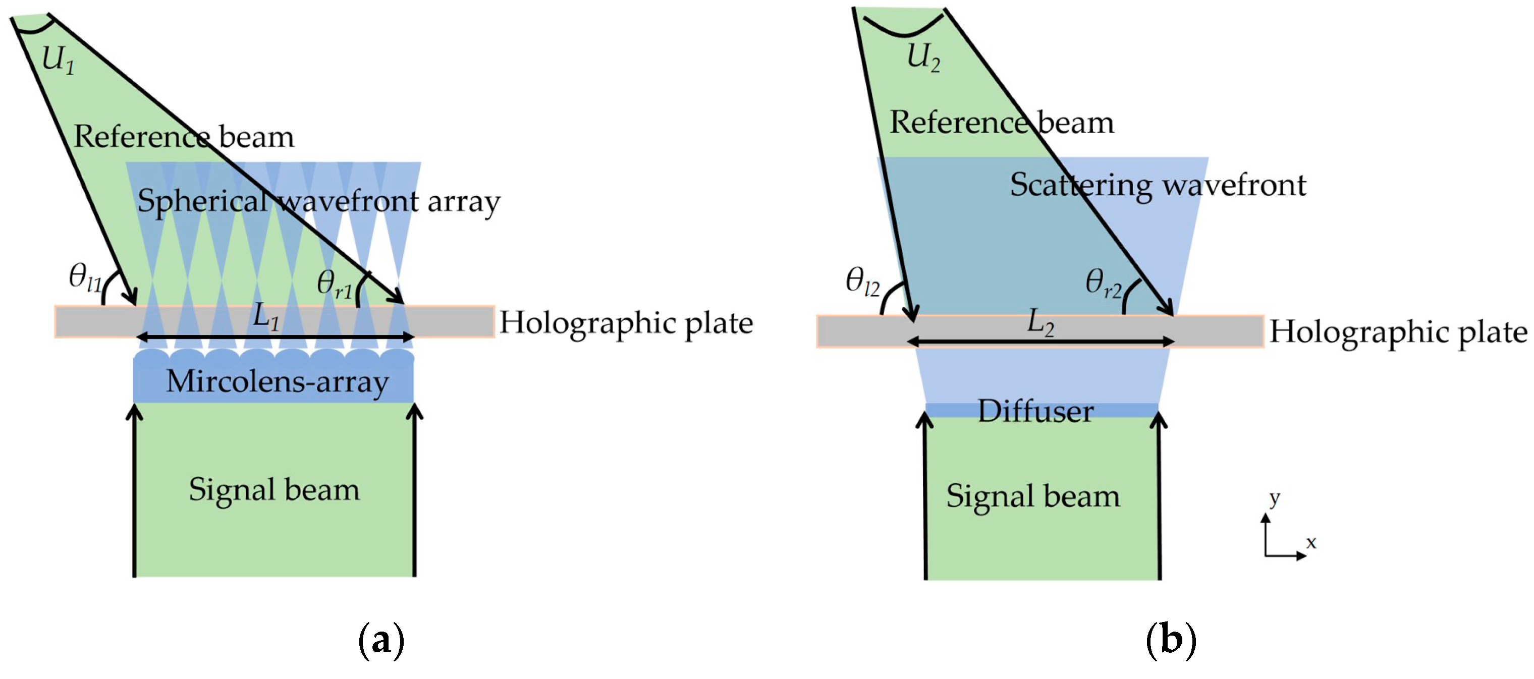
3.1. Fabrication of Variable-Focus Liquid Lens and MHOE

In experiments, we fabricated a variable-focus liquid lens. The operating mechanism of the liquid lens is that its focal length is controlled by pumping liquid in and out of the lens chamber, which, in turn, changes the curvature of the liquid profile. Therefore, the volume of pumping liquid is controlled to adjust the diopter of the liquid lens to satisfy two Bragg diffraction conditions. The radius of curvature (R) and volume change ΔV follow the relationship [23]:
Δ V = π 3 ( 2 R 2 d 2 4 2 R R 2 d 2 4 ) ( 2 R + R 2 d 2 4 ) ,
where d is the diameter of the lens aperture. The variable-focus liquid lens is considered as a thin lens, and its effective diopter (φ) can be calculated:
φ = ( n 1 ) R ,
where the refractive index of the liquid in the experiment is n′ = 1.33. Figure 4a shows the changes in the radius of curvature R and diopter φ with the variation in volume change ΔV. In the practical experiment, the φ was 14.29D and the R was 23 mm, which we chose while ΔV was 8.6 mL. Figure 4b,c show the lens effects with the lens diopter of 0D and 14.29D, respectively.
Figure 5a,b show the experimental setups for the two-step recording of MHOE. The fabricated variable-focus liquid lens was placed in the optical path of the reference beam to change the incident angles of the reference beam to match the Bragg diffraction conditions. The detailed parameters are shown in Table 1. The pitch and focal length of the recorded MLA are 1 mm and 3.3 mm, respectively, and the scattering angle of the diffuser is 20°.
In order to obtain high diffraction efficiency, we actually used two holographic plates and recorded each optical element independently. The MHOE was obtained by using a frame (GCM-1301M in Daheng Optics) to clip the two holographic plates together. The fabricated MHOE was tested with reference beams under the corresponding Bragg diffraction conditions. Figure 6a,b show the diffraction effects of the MLA and diffuser, respectively. The real-world scene behind the MHOE is clearly observed without visual obstruction, which verifies the see-through properties of MHOE, as shown in Figure 6c. Figure 6d shows the relation between normalized diffraction efficiency and angle deviation. The diffraction efficiency starts to decline sharply at about ±5°. The angular difference between the two Bragg matching angles is 12.2°, which is large enough to avoid the crosstalk between the two display modes.

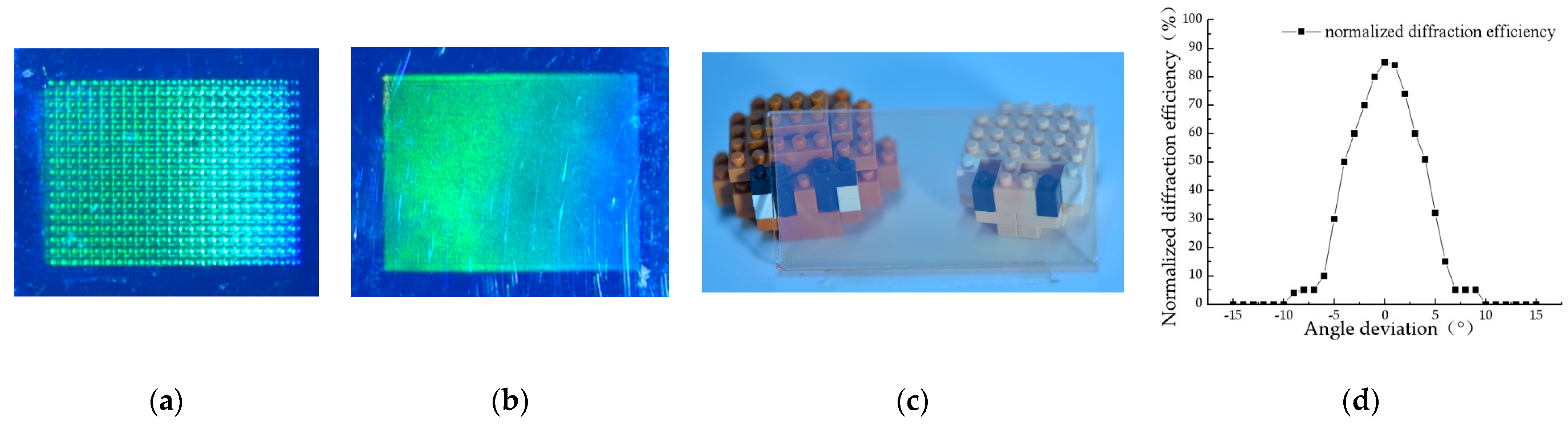
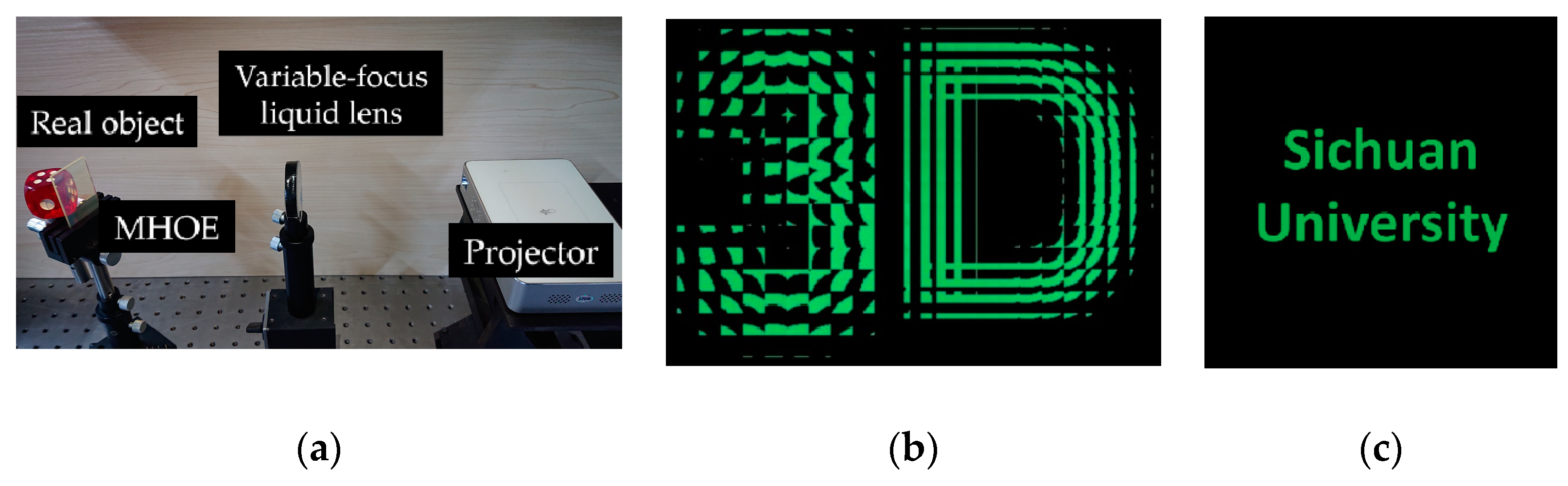
3.2. Experimental Results

We developed the experimental system based on the proposed scheme as shown in Figure 7a. The projector has the resolution of 1280 × 800. The projected image for the 3D mode is provided as shown in Figure 7b. The character “3” and letter “D” are in front of the MHOE with the depth of 35 mm and behind the MHOE with the depth of −35 mm, respectively. In addition, a 2D text “Sichuan University” is prepared for 2D display as shown in Figure 7c.
On the 3D display mode, the projected beam meets the Bragg diffraction condition 1. The 3D image is reconstructed, and four different perspectives from top left, top right, bottom left and bottom right viewing points are shown in Figure 8a. Obvious horizontal and vertical parallaxes can be clearly seen. Additionally, the character “3” is bigger than letter “D”, which demonstrates that “3” is reconstructed in front of the MHOE while “D” is behind the MHOE. On the 2D display mode, the projected beam satisfies the Bragg diffraction condition 2, and Figure 8b shows the displayed 2D image. The real object “dice” behind the MHOE is always visible on both 2D and 3D display modes, which verifies the good optical see-through properties of the system.

4. Conclusions

In this paper, an optical see-through 2D/3D compatible display system is proposed by using a variable-focus lens and a MHOE. The scattering wavefront and spherical wavefront array are recorded in the MHOE using angular multiplexing technology to achieve 2D/3D display, respectively. The variable-focus lens is used to adjust the incident angles of the projected beam. By analyzing the relationship between the liquid change and the radius of curvature of the variable-focus lens, the optimal diopter of the variable-focus lens is picked up to match the Bragg diffraction conditions. The incident angles of the projected beam are calculated and measured. When the MLA and diffuser were recorded on holographic plates based on angular multiplexing technology, the variable-focus lens is placed in the path of the reference beam to adjust the incident angles of the reference beam through the variation in the liquid pumping volume. During reconstruction, the incident angles of the projected beam satisfied the Bragg matching angles under the same amount of liquid pumping volume, and the spherical wavefront array of the MLA and the scattering wavefront of diffuser are reconstructed. As a result, 3D images with proper horizontal and vertical parallaxes are reconstructed on 3D display mode and 2D image is displayed on 2D display mode, and both modes show good optical see-through properties. The images; quality would be further improved if a variable-focus liquid lens with multi-chamber is used. The proposed system can be a good candidate in AR application.

Author Contributions

Conceptualization, Q.J.; methodology, H.D., H.Z. and W.J.; software, F.Z.; validation, Q.J. and F.R.; data curation and writing-original draft preparation, Q.J.; writing—review and editing, H.D. All authors have read and agreed to the published version of the manuscript.

Funding

This research was funded by the National Natural Science Foundation of China, grant numbers 61972147 and 61775151, and the China Postdoctoral Science Foundation, grant number 2021M690287.

Institutional Review Board Statement

Not applicable.

Informed Consent Statement

Not applicable.

Data Availability Statement

The data that support the findings of this study are available from the corresponding author upon reasonable request.

Conflicts of Interest

The authors declare no conflict of interest.

References

  1. Zhou, F.; Duh, H.B.L.; Billinghurst, M. Trends in augmented reality tracking, interaction and display: A review of ten years of ISMAR. In Proceedings of the 7th IEEE/ACM International Symposium on Mixed and Augmented Reality, Washington, DC, USA, 15–18 September 2018; pp. 193–202. [Google Scholar]
  2. Lee, Y.H.; Zhan, T.; Wu, S.T. Prospects and challenges in augmented reality displays. Virtual Real. Intell. Hardw. 2019, 1, 10–20. [Google Scholar] [CrossRef]
  3. Murdoch, M.J. Brightness matching in optical see-through augmented reality. J. Opt. Soc. Am. A 2020, 37, 1927–1936. [Google Scholar] [CrossRef] [PubMed]
  4. Xie, S.L.; Wang, P.; Sang, X.Z.; Li, C.Y. Augmented reality three-dimensional display with light field fusion. Opt. Express 2016, 24, 11483–11494. [Google Scholar] [CrossRef] [PubMed]
  5. Deng, H.; Li, Q.; He, W.; Li, X.W.; Ren, H.; Chen, C. 2D/3D mixed frontal projection system based on integral imaging. Opt. Express 2020, 28, 26385–26394. [Google Scholar] [CrossRef] [PubMed]
  6. Li, Q.; He, W.; Deng, H.; Zhong, F.Y.; Chen, Y. High-performance reflection-type augmented reality 3D display using a reflective polarizer. Opt. Express. 2021, 29, 9446–9453. [Google Scholar] [CrossRef]
  7. Martínez-Corral, M.; Javidi, B. Fundamentals of 3D imaging and displays: A tutorial on integral imaging, light-field, and plenoptic systems. Adv. Opt. Photonics 2018, 10, 512–566. [Google Scholar] [CrossRef] [Green Version]
  8. Javidi, B.; Moon, I.; Yeom, S. Three-dimensional identification of biological microorganism using integral imaging. Opt. Express 2006, 14, 12096–12108. [Google Scholar] [CrossRef]
  9. Hong, J.; Min, S.W.; Lee, B. Integral floating display systems for augmented reality. Appl. Opt. 2012, 51, 4201–4209. [Google Scholar] [CrossRef]
  10. Shen, X.; Javidi, B. Large depth of focus dynamic micro integral imaging for optical see-through augmented reality display using a focus-tunable lens. Appl. Opt. 2018, 57, B184–B189. [Google Scholar] [CrossRef]
  11. Deng, H.; Xiong, Z.L.; Xing, Y.; Zhang, H.L.; Wang, Q.H. A high optical efficiency 3D/2D convertible integral imaging display. J. Soc. Inf. Disp. 2016, 24, 85–89. [Google Scholar] [CrossRef]
  12. Choi, H.; Cho, S.W.; Kim, J.; Lee, B. A thin 3D-2D convertible integral imaging system using a pinhole array on a polarizer. Opt. Express 2006, 14, 5183–5190. [Google Scholar] [CrossRef] [PubMed]
  13. Ren, H.; Xing, Y.; Zhang, H.L.; Li, Q.; Wang, L.; Deng, H.; Wang, Q.H. 2D/3D mixed display based on integral imaging and a switchable diffuser element. Appl. Opt. 2019, 58, G276–G281. [Google Scholar] [CrossRef]
  14. Zhang, Y.A.; Jin, T.; He, L.C.; Chu, Z.H.; Guo, T.L.; Zhou, X.T.; Lin, Z.X. Controllable liquid crystal gratings for an adaptive 2D/3D auto-stereoscopic display. Opt. Commun. 2017, 384, 16–24. [Google Scholar] [CrossRef]
  15. Hua, H.; Javidi, B. A 3D integral imaging optical see-through head-mounted display. Opt. Express 2014, 22, 13484–13491. [Google Scholar] [CrossRef] [PubMed]
  16. Huang, H.; Hua, H. High-performance integral-imaging-based light field augmented reality display using freeform optics. Opt. Express 2018, 26, 17578–17590. [Google Scholar] [CrossRef] [PubMed] [Green Version]
  17. Deng, H.; Chen, C.; He, M.Y.; Li, J.J.; Zhang, H.L.; Wang, Q.H. High-resolution augmented reality 3D display with use of a lenticular lens array holographic optical element. J. Opt. Soc. Am. A 2019, 36, 588–593. [Google Scholar] [CrossRef] [PubMed]
  18. Kim, S.B.; Park, J.H. Optical see-through Maxwellian near-to-eye display with an enlarged eyebox. Opt. Lett. 2018, 43, 767–770. [Google Scholar] [CrossRef] [PubMed]
  19. Jang, C.; Lee, C.K.; Jeong, J.; Li, G.; Lee, S.; Yeom, J.; Hong, K.; Lee, B. Recent progress in see-through three-dimensional displays using holographic optical elements. Appl. Opt. 2016, 55, A71–A85. [Google Scholar] [CrossRef] [PubMed]
  20. Yeom, J.; Jeong, J.; Jang, C.; Li, G.; Hong, K.; Lee, B. Three-dimensional/two-dimensional convertible projection screen using see-through integral imaging based on holographic optical element. Appl. Opt. 2015, 54, 8856–8862. [Google Scholar] [CrossRef]
  21. Chou, P.Y.; Wu, J.Y.; Huang, S.H.; Wang, C.P.; Qin, Z.; Huang, C.T.; Hsieh, P.Y.; Lee, H.H.; Lin, T.H.; Huang, Y.P. Hybrid light field head-mounted display using time-multiplexed liquid crystal lens array for resolution enhancement. Opt. Express 2019, 27, 1164–1177. [Google Scholar] [CrossRef]
  22. Zhang, H.L.; Deng, H.; Li, J.J.; He, M.Y.; Li, D.H.; Wang, Q.H. Integral imaging-based 2D/3D convertible display system by using holographic optical element and polymer dispersed liquid crystal. Opt. Lett. 2019, 44, 387–390. [Google Scholar] [CrossRef] [PubMed]
  23. Ren, H.; Fox, D.; Andrew Anderson, P.; Wu, B.; Wu, S.T. Tunable-focus liquid lens controlled using a servo motor. Opt. Express 2006, 14, 8031–8136. [Google Scholar] [CrossRef] [PubMed]
Figure 1. Schematic diagrams of system structure: (a) 3D image reconstruction when the probe beam satisfies the Bragg diffraction condition 1; (b) 2D image display when the probe beam satisfies the Bragg diffraction condition 2.
Photonics 08 00297 g001
Figure 2. The projected beam matching with the Bragg matching angles under different diopters of the variable-focus lens: (a) 3D mode; (b) 2D mode.
Photonics 08 00297 g002
Figure 3. Two-step recording process of MHOE: (a) First recording with the MLA; (b) second recording with the diffuser.
Photonics 08 00297 g003
Figure 4. Variable-focus liquid lens: (a) Curves of the radius of curvature and the diopter of liquid lens with the variation in the volume change; (b) imaging effect at 0D; (c) Imaging effect at 14.29D.
Photonics 08 00297 g004
Figure 5. Experimental setups for the two-step recording of MHOE: (a) Recording of MLA, (b) recording of a diffuser. ES, electronic shutter; SF, spatial filter; CL, collimating lens; BS, beam splitter; M1, M2, mirror; HP, holographic plate.
Photonics 08 00297 g005
Figure 6. Performance testing of MHOE: (a) Diffraction effect of the MLA; (b) diffraction effect of the diffuser; (c) optical see-through properties of MHOE; (d) relationship between normalized diffraction efficiency and angle deviation.
Photonics 08 00297 g006
Figure 7. (a) Experimental system; (b) elemental image array; (c) 2D image.
Photonics 08 00297 g007
Figure 8. Experimental results of 2D/3D compatible display with optical see-through properties: (a) 3D images display captured from four different viewing directions; (b) 2D image display.
Photonics 08 00297 g008
Table 1. Parameters of the experiment for recording process.
ComponentsParametersValues
Bragg diffraction conditionsBragg matching angles 1θl157.2°
θr132.8°
Bragg matching angles 2θl245°
θr245°
Recording regionWidth L123 mm
Width L218 mm
MLAPitch1 mm
Focal length3.3 mm
DiffuserScattering angle20°
Photopolymer plateThickness15 ± 1 µm
Sensitive wavelength532 nm
Sensitivity10 mJ/cm²
Averaged refractive index1.47
Refractive index modulation>0.02
Publisher’s Note: MDPI stays neutral with regard to jurisdictional claims in published maps and institutional affiliations.

