Review

Magnetic Holography and Its Application to Data Storage

Department of Electrical and Electronic Information Engineering, Toyohashi University of Technology, Toyohashi 441-8580, Japan
Photonics 2021, 8(6), 187; https://doi.org/10.3390/photonics8060187
Submission received: 30 April 2021 / Revised: 19 May 2021 / Accepted: 22 May 2021 / Published: 25 May 2021
(This article belongs to the Special Issue Holography)

Abstract

:
The principle of magnetic holograms and its application to holographic memory are reviewed. A magnetic hologram was recorded through a thermomagnetic recording as a difference in magnetization direction and reconstructed with the magneto-optical effect. To achieve a bright reconstruction image, it is important to record deep magnetic fringes on the materials with large Faraday rotation coefficients. This technique was applied to the holographic memory using transparent magnetic garnets as a recording material. The first reconstruction image was dark and noisy, but improvements in the recording conditions resulted in error-free recording and reconstruction of the magnetic hologram. To form deep magnetic fringes, insertion of heat dissipation (HD) layers into recording layer was proposed. It was found that this HD multilayer medium showed diffraction efficiency higher than that of a single layer medium, and error-free recording and reconstruction were also achieved, using magnetic assisted recording. These results suggest that HD multilayer media have potential applications in recording media of magnetic holographic data storage. In future, a high recording density technique, such as multiple recording, should be developed.

1. Introduction

Holography is a technology that records and reconstructs light from an object (object or signal light), using interference and diffraction. The light from the object and the reference light interfere with each other, and this interference pattern, recorded on a recording medium, is called a hologram. When only the reference light is irradiated on this hologram, the waveform of the original light from the object is reconstructed as it is through diffraction by the interference fringes. Therefore, holography is an ideal three-dimensional image reconstruction technique because the image reconstructed from the hologram can be seen as it is, even if the viewing angle is changed. In holography, the interference fringes are recorded volumetrically, and the signal light can be reconstructed one by one from the holograms recorded in the same place with slightly different conditions, for example, by changing the angle or phase of the reference and signal lights because the interference conditions are strict. Holographic technology is expected to be applied to holographic data storage with large capacity and a high data transfer rate since a large amount of data can be recorded in the same place and reconstructed at once by showing two-dimensional data as the signal light [1,2,3,4,5,6,7,8,9,10,11,12,13,14,15,16,17].
There are various types of holography, but two methods are mainly used as optical interference systems for the recording and reconstruction of holographic memory; one is the two-beam interference method in which signal and reference lights are irradiated from different angles and interfered (Figure 1a), and the other is the collinear (or coaxial) holographic interference method in which signal and reference lights are formed in a spatial light modulator (SLM) and interfered in the same axis (Figure 1b) [12,13,14,15,16,17]. In general, the former is widely used, while the latter can use a similar optical system to that of the conventional Digital Versatile Disc and the Blu-ray Disc and has an advantage against vibration.
A photoreactive photopolymer is generally used for hologram recording material, and a hologram is formed as a difference in the refractive index of the material, in general. This shows large diffraction efficiency, which is an index of the brightness of the reconstruction image, while there are issues with the volume change associated with the photoreaction and material stability. Contrastingly, a magnetic hologram that is formed as the difference in the magnetization direction of a recording magnetic material was proposed by Mezrich [18] in 1969. Magnetic holograms are recorded by a thermomagnetic recording (Curie point writing) method [18,19,20,21,22] and reconstructed using the rotation of the polarization plane through a magneto-optical effect [18,20,21,22,23].
We developed magnetic holograms and their application technologies, using transparent bismuth substituted rare earth iron garnet (Bi:RIG) as the recording material [24,25,26,27,28,29,30,31,32,33,34]. Since magnetic garnet is an oxide, it is substantially a very stable recording material, and by recording on a magnetic material with appropriate translucency, it is possible to record volumetric holograms. Holographic memory using this as a recording material is also expected to realize a rewritable (reformattable) hologram memory, and there are no issues of volume change and shading that may occur with photopolymers. In this paper, the principle of magnetic holograms and its application to magnetic hologram memory are reviewed.

2. Principles of Recording and Reconstruction of Magnetic Holography

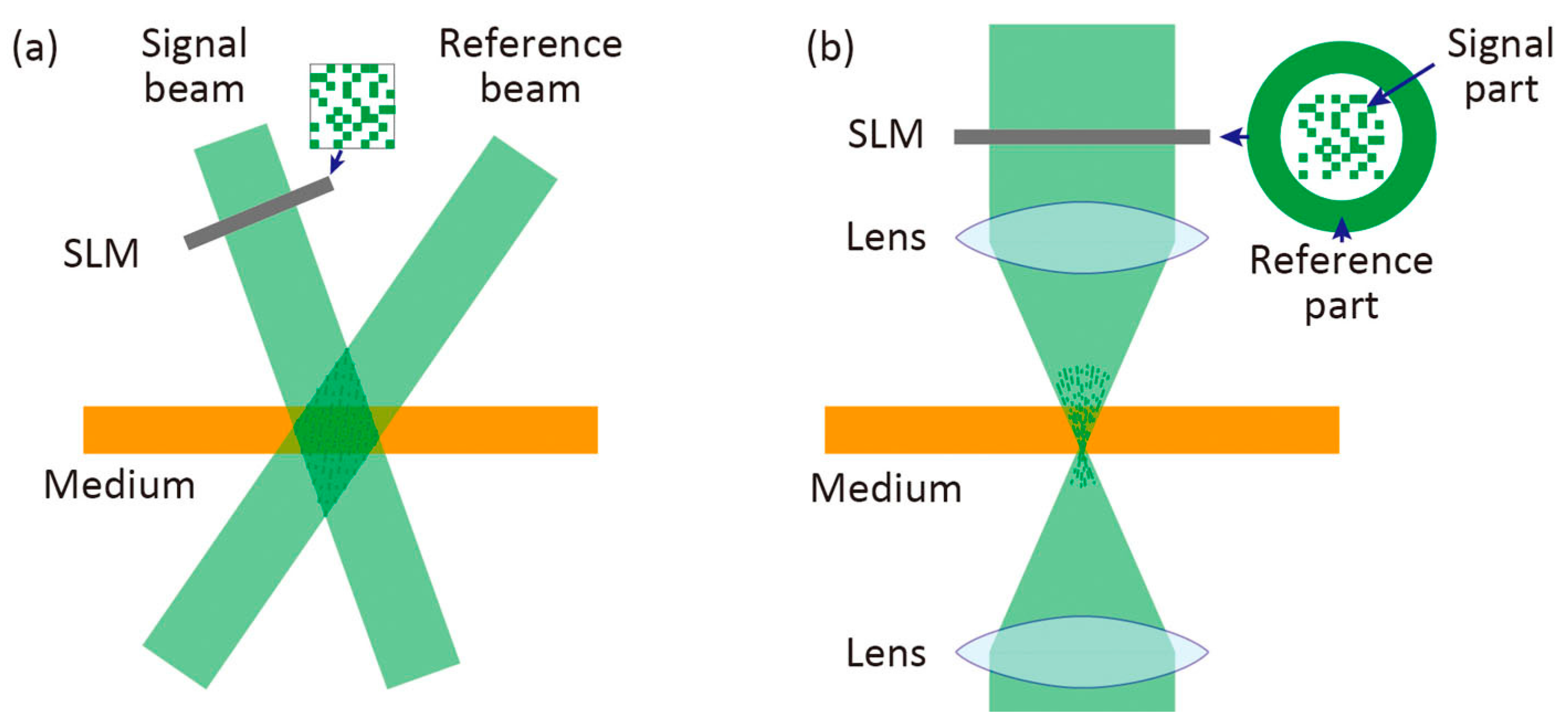
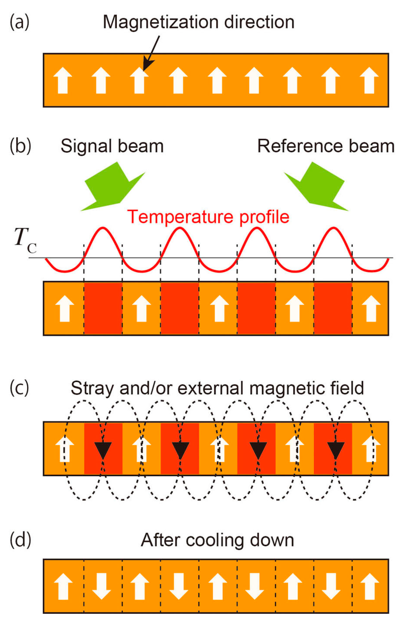
2.1. Recording of Magnetic Hologram

The thermomagnetic recording method is used for recording magnetic holograms. Figure 2 schematically shows the recording process of a magnetic hologram. Reference and signal beams are irradiated on a perpendicularly magnetized film, and the intensity distribution of light is formed due to light interference. The temperature distribution is formed corresponding to the light intensity distribution through the absorption of light, and the magnetization of the regions exceeding the Curie temperature, TC, disappears. In the subsequent cooling process, the direction of magnetization is reversed by stray magnetic fields from the surrounding magnetization, so that a magnetic hologram is formed as the difference in the direction of magnetization.
The effect of heat generated by the absorption of light is important to form clear magnetic fringes by thermomagnetic recording. The magnetic hologram is formed by the thermally demagnetized regions where the temperature exceeds the Curie temperature due to the absorption of light, while this heat diffuses to the low temperature regions in the magnetic film. This heat diffusion effect becomes greater in the case of recording on the materials with large heat conduction, especially in the metal film. In this case, if the energy density for recording is small, the generated heat diffuses before the temperature rises to the Curie temperature, and the temperature of the entire film rises; therefore, we cannot obtain a clear magnetic fringe. Chen et al. reported that the pulse width of the laser should be on the order of 10 ns or less to form magnetic fringes on MnBi films [35]. Nakamura et al. [25] also reported the effect of the period of the interference fringe and the pulse width of the laser radiation on the shape of the magnetic fringe in a magnetic garnet film with low thermal conductivity with a numerical simulation. They reported that the depth of the magnetic fringe of 500 line-pair/mm, in which the period of the interference fringe is 2 µm, is deeper than that of 1500 line-pair/mm in which the period of the interference fringe is 0.667 µm; a laser pulse of 50 ps is desirable for recording clear and deep magnetic fringes of 1500 line-pair/mm, compared to 25 ns. These results show that lateral thermal diffusion during thermomagnetic recording is important for the formation of magnetic fringes, that is, the wider the distance between fringes, the smaller the effect of thermal diffusion; the effect of thermal diffusion during irradiation can be reduced, using the high energy and short pulse laser. In addition, Lee et al. [36] reported that when the average temperature in the film during thermomagnetic recording exceeds the Curie temperature, the magnetization of the entire region disappears. Therefore, the total recording energy should not be too large. This heat diffusion effect is discussed later in Section 3.3, and a method reducing this effect to form deep magnetic fringes is proposed.

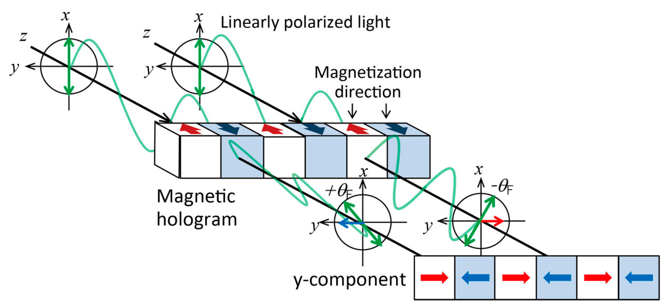
2.2. Reconstruction from Magnetic Hologram

The magneto-optical effect is used for reconstruction of a magnetic hologram. The magneto-optical effect is a phenomenon in which the polarization plane rotates depending on the direction and strength of magnetization when linearly polarized light is incident on a magnetic material. The magneto-optical effect on transmitted light is called the Faraday effect, and that on reflected light is called the Kerr effect. Figure 3 schematically shows the reconstruction principle for transmitted light. When linearly polarized light is incident on the magnetic grating, the polarization plane rotates in the opposite direction depending on the direction of magnetization. At this time, when we see the component in the direction orthogonal to the polarization plane of incident light, the light has a phase difference of 180°. When the reference light is incident on the magnetic hologram, this component of the diffracted light interferes with each other, so that the signal light is reconstructed by the principle of the phase hologram [21,22,23]. The S/N ratio of the reconstructed light can be improved, therefore, by separating only the component orthogonal to the incident light polarization plane, using the analyzer [18].
Hascal [23] discussed in detail the reconstruction principle and diffraction efficiency of magnetic holograms. In a binary magnetic hologram, the polarization plane of diffracted light is orthogonal to that of the incident light. On the other hand, in a magnetic hologram with magnetization distribution, such as a trigonometric function, an even order diffracted light, including the 0th order transparent light, has a polarization plane that is the same as that of the incident light, while the polarization plane of the odd order diffracted light is orthogonal to that of the incident light. In either case, the strength of the diffracted light of the second order or higher is sufficiently weak, so the first order diffraction light that has a polarized plane orthogonal to the incident light is used. Theoretically, the diffraction efficiency η of the first-order diffracted light is described as follows:
η = sin2(θF) ~ θF2 = (Ft)2
with the rotation angle θF of the magnetic hologram as θF = Ft, where F is the Faraday rotation coefficient representing the rotation angle per unit thickness, and t is the depth of the magnetic hologram, respectively. This diffraction efficiency η is an index of the brightness of the reconstructed image, and a bright reconstructed image can be obtained by forming a deep volumetric magnetic hologram on the recording material with a large rotation angle per unit thickness. Equation (1) shows that the diffraction efficiency decreases when the Faraday rotation angle exceeds 90 degrees. However, for example, the Faraday rotation angle of a typical bismuth-substituted rare earth iron garnet is about several deg./µm at a wavelength of 532 nm, and, as will be described later, the recording depth by thermomagnetic recording is about 1 to 2 µm. On the other hand, magnetic metal films, such as MnBi, show a rotation angle of several tens of deg./µm, while the recording depth is only 100 nm or less due to large light absorption. Hence, we need not worry that the rotation angle becomes too large since the rotation angle of the magnetic hologram will be less than 10 degrees. Therefore, the recording conditions for recording the magnetic hologram as deeply as possible are desirable.
Tanaka et al. [37] recorded interference fringes on the Bi–Mn film by the two-beam interference method and experimentally showed that the diffraction efficiency was proportional to the 2.3rd power of the Faraday rotation angle, which is in good agreement with the theory. In addition, Chen et al. [35,38] recorded and reconstructed a two-dimensional dot pattern on the Bi–Mn film and proved that complex two-dimensional patterns can be recorded and constructed with magnetic holograms. Nakamura et al. [25] reported that the diffraction efficiency of the magnetic fringe with 500 line-pair/mm was larger than that with 1500 line-pair/mm. The diffraction efficiency is theoretically independent of the fringe spacing, but the depth of the magnetic fringe with 500 line-pair/mm was deeper than that with 1500 line-pair/mm from the numerical simulation as mentioned in Section 2.1. Therefore, this large diffraction efficiency was thought to be attributed to the deep magnetic fringe from Equation (1).

3. Magnetic Holographic Memory

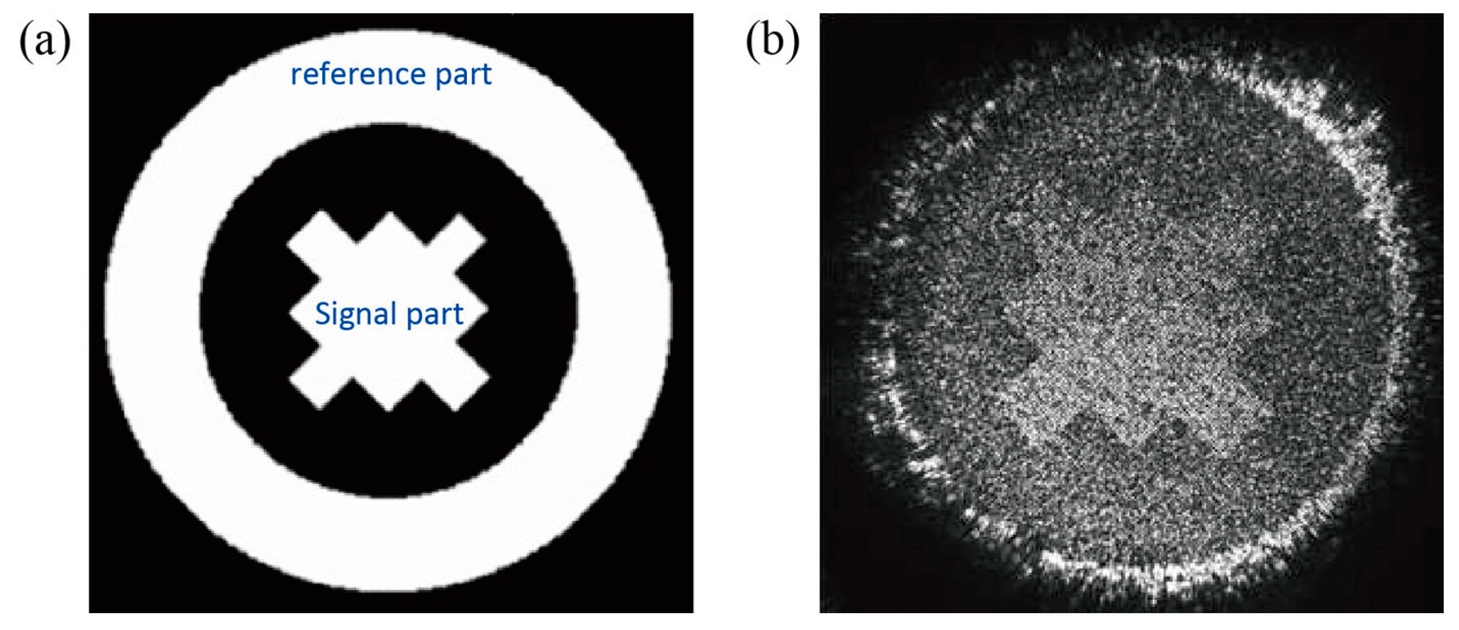
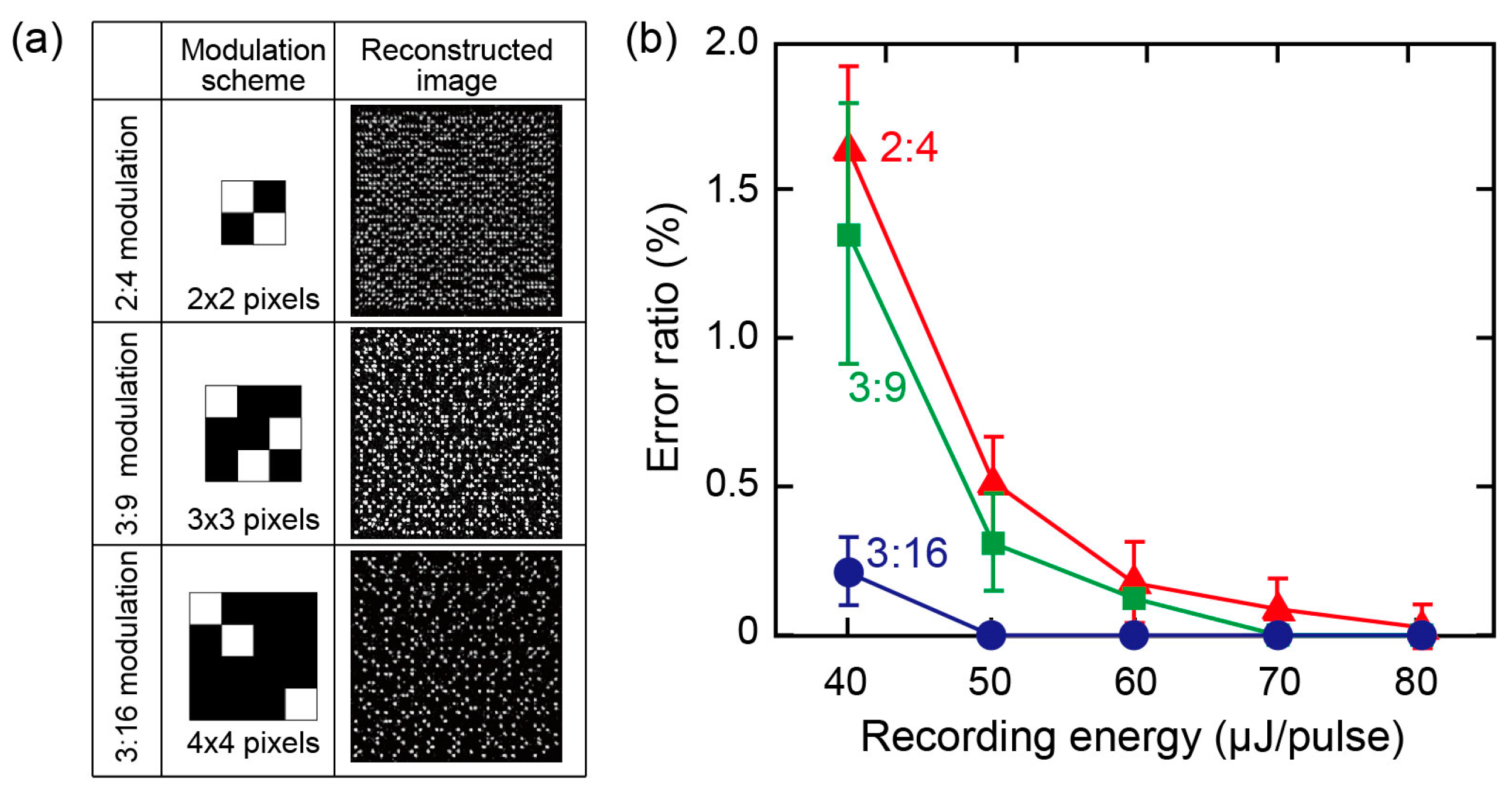
3.1. Reconstructed Image and Error Ratio of Magnetic Holography
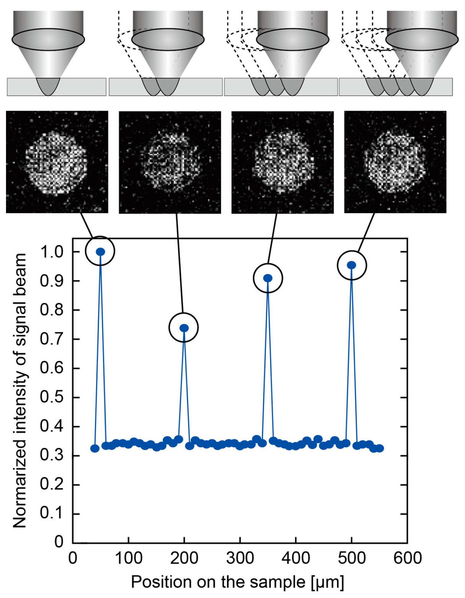
Nakamura et al. [24] reported the recording and reconstruction of magnetic holograms on bismuth-substituted rare earth iron garnet (Bi:RIG) film, using the collinear interference method for the first time. The reconstruction image is shown in Figure 4. As shown in this figure, the first reported reconstruction image of the collinear magnetic holography was dark and noisy with large background noise. In order to improve this reconstruction image, the recording conditions, including the optical system and the recording material, were investigated.
This early collinear optical system used an optical diffuser to avoid excessive concentration of recording energy. However, since the pixels of the reconstruction image were blurred by inserting the diffuser, the diffuser was removed, and the recording conditions were changed. The effects of the signal and reference light shapes and recording position for recording were investigated, and the suitable conditions to give a clear reproduction image were found at the position away from the focus position [30]. As a result, the suitable defocused recoding condition was found desirable for obtaining a clear reconstruction image.
In addition, readout errors during reconstruction are reduced by limiting 2D signal patterns to specific ones, using appropriate data modulation schemes [12,39]. Since the interference pattern in recording is affected by the data pattern, the modulation method is important for magnetic holograms recorded by thermomagnetic recording. Among the various modulation methods, Nakamura et al. [30] reported the effect of the 2:4, 3:9, and 3:16 modulations of signal data on the pixel error ratio. As a result, error-free reconstruction could be achieved in these three modulation methods as shown in Figure 5, and the 3:16 modulation method, using 3 out of 16 pixels, which has the smallest white ratio in these modulation patterns, was found suitable for achieving stable, error-free recording under low recording energy conditions.

3.2. Multiplexity

In holographic memory, multiple recording is an important technique for achieving high recording density. Several multiplexing techniques are proposed, such as shift multiplexing, angular multiplexing, and phase multiplexing [8,40,41,42,43,44,45,46,47,48,49,50,51,52,53,54,55,56,57]. Nakamura et al. reported the results of shift multiplexing recorded on the magnetic garnet film in collinear magnetic holograms [24]. Figure 6 shows the reconstructed images of four circular signal light spots recorded with a shift pitch of 150 µm, and the intensity of the reconstructed signal light measured at 10 µm intervals. The diameter of each hologram was about 330 µm, so the second and third holograms completely overlapped with the adjacent ones as schematically shown in Figure 6. The intensities of reconstructed light at the positions where the signal lights were recorded were sufficiently high despite the background noise, and the recorded signal light could be reconstructed separately. Although the recording density was not high, this demonstrated that multiple recording is possible, even in magnetic hologram memory.

3.3. Recording Media

3.3.1. Properties of Single Layer and Magnetic Microcavity Media

An increase in the Faraday rotation angle of the magnetic hologram is required to obtain bright reconstruction images, so it is needed to form a deep hologram in the recording media with a large Faraday rotation coefficient as shown in Equation (1). In the early research on magnetic holography [18,19,20,21,22,23], magnetic metal films, such as Bi–Mn, were used. However, the depth of the hologram was only several 100 nm, and deep holograms cannot be formed with such metals because of poor transparency. So, the transparent magnetic rare earth iron garnets, which have a Faraday rotation coefficient of about 2 deg./µm or higher depending on the composition, are favorable [58,59,60,61].
Improvement in the recording material is usually needed to increase the Faraday rotation coefficient, but even if the same material is used, the rotation angle can be increased by using magneto photonic microcavities (MPMs) [26,27,28,29,62,63,64]. The MPM is a stacked medium in which a transparent magnetic film is sandwiched between two Bragg mirrors and this structure acts as an optical cavity for enhancing the Faraday rotation angle. Isogai et al. reported the relationship between the MPM structure and the diffraction efficiency with numerical simulation [26,27] and showed that the use of MPM recording media is effective in achieving high diffraction efficiency. Furthermore, recording and reconstruction on the MPM recording medium with 1 µm thick garnet cavity was performed, using the collinear optical system, and a reconstruction image brighter than that of the single-layer medium with the same thickness was shown experimentally [28].
On the other hand, a simple way for recording a deep magnetic hologram is to record with large recording energies. To see the effect of the recording energy on the diffraction efficiency, a numerical simulation of the two-beam interferometry with 1500 line-pairs/mm was carried out [25,33], and the results are shown in Figure 7. As shown in Figure 7a, the diffraction efficiency was not improved much, even when recording on a thick magnetic film was performed with high recording energy. This is attributed to the effect of the heat diffusion generated during thermomagnetic recording as mentioned in Section 2.1. Thermomagnetic recording is performed by local heating above the Curie temperature through the absorption of light. At this time, the excess heat diffuses to the places below the Curie temperature. When the average temperature in the recording region exceeds to about twice the Curie temperature, the entire temperature in that region rises above the Curie temperature, resulting in the disappearance of the information of interference patterns. Figure 7b shows the calculated temperature change around the 3.1 µm thick Bi:RIG medium after laser radiation from the air by two-beam interferometry with the energy of 81 mJ/cm2 for 50 ps. As shown in this figure, immediately after the laser radiation, the shape of the parts above the Curie temperature (150 °C) has a shape corresponding to the interference fringes, while the maximum temperature at the film surface reaches 400 °C, which is higher than twice the Curie temperature. With the passage of time, the heat of these high temperature regions diffuses laterally, and the temperature near the surface rises to higher than 150 °C. Hence, the fringes grow wider and merge with adjacent ones near the surface. After 20 ns, the temperature near the surface within 1 µm becomes higher than the Curie temperature as expected. Consequently, the fringes are completely merged near the surface as shown in Figure 7c, while the tip of the fringe reaches the bottom of the film. The effective magnetic fringe depth finally formed is limited to about 1.4 µm and is found almost constant regardless of the high recording energy, so the diffraction efficiency cannot be improved by simply increasing the recording energy [33].

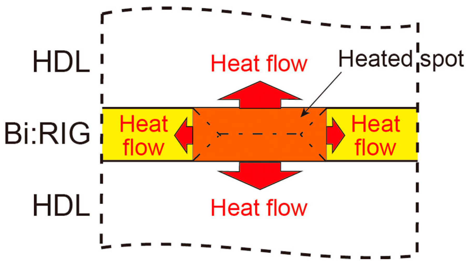
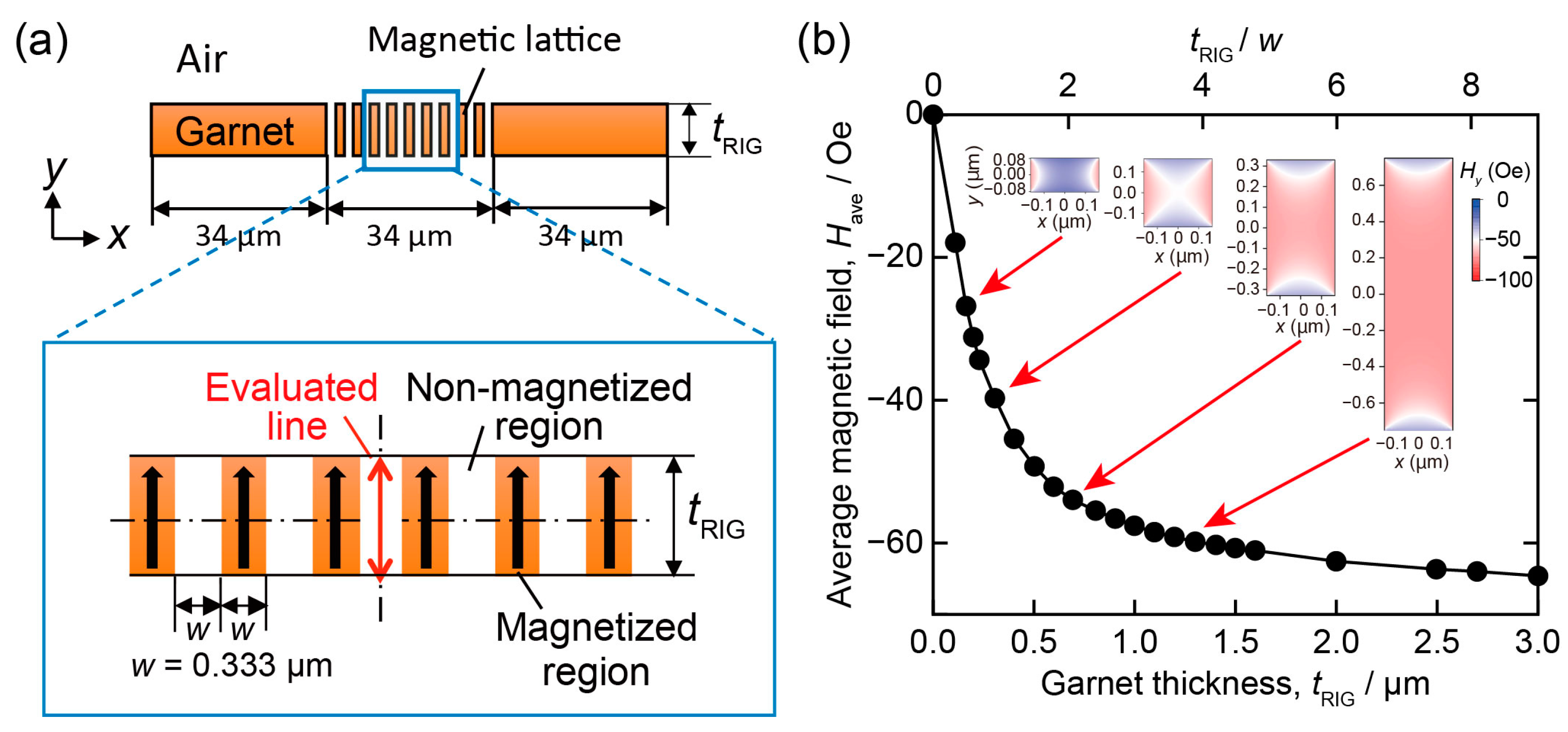
3.3.2. Concept and Properties of Heat Dissipation Multilayer Media

To reduce the effect of the heat diffusion and to form deep magnetic fringes, Isogai et al. [29] and Nakamura et al. [32,33,34] proposed multilayer media in which heat dissipation layers (HDLs) with no light absorption are introduced between the magnetic layers. The basic concept is shown in Figure 8. By diffusing the excess heat generated in the magnetic film to the HDLs, the heat diffusing into the magnetic layer decreases, and the increase in the region where the magnetization is disappeared by heat diffusion is suppressed. When inserting HDLs, it is necessary to consider, optically, the effect of multiple reflections due to the difference in refractive index between the HDLs and Bi:RIG layers. Ideally, no difference in the refractive index between them is desirable, but it is difficult to select such materials. Hence, Isogai et al. [29] proposed that the optical thickness of each HDL is set to an integral multiple of a half wavelength. In this case, the electric field distribution in the magnetic layer is expected to be identical to those before the insertion of HDLs, except for the sign. The numerical simulations [33] suggested that the clear magnetic fringes can be formed up to the entire thickness of the, in total, 3.1 µm thick Bi:RIG layers by introducing the appropriate HDLs. As the result, the diffraction efficiency became approximately four times larger than that of the single layer medium, which is the same as the theoretically expected one.
In the HD multilayer media, since the thickness of the magnetic layer becomes thin, it may affect the magnetic reversal by stray magnetic field during thermomagnetic recording. Shirakashi et al. [31,32] investigated the effect of magnetic layer thickness on the stray magnetic field with numerical simulation. In this simulation, the magnetization of the garnet film was set to be 135 G perpendicular to the surface, and the magnetic field distribution was calculated for various garnet film thicknesses, tRIG, for the same fringe period of 2w = 0.667 µm, and the result is shown in Figure 9. When the ratio of garnet thickness to demagnetized region width, tRIG/w, decreased, the average stray magnetic field in the center of demagnetized region was found to become small. This small stray magnetic field led to the insufficient magnetic reversal and reduction in diffraction efficiency. The magnetic assisted recording in which the magnetic hologram is recorded under applying an external magnetic field in the direction opposite to the initial magnetization, is effective to overcome this issue. Shirakashi et al. [31] reported that clear reconstruction images can be obtained, using the magnetic assisted recording technique, and that recording and reconstruction without error are possible even under relatively low recording energy recording condition. The diffraction efficiency of HD multilayer medium tends to be lower than that of the single layer film without the magnetic assist, but it became equal to or higher than that of the single layer film under proper magnetic assisted recording conditions [32].
To determine the thickness of each layer in the HD multilayer medium, Nakamura et al. [33,34] proposed a designing method based on a simple energy conservation law. In this model, the ratio of thermal diffusivities of the magnetic layer to HDL, expressed as Equation (2), is an important parameter.
α Mag α HDL = k Mag C HDL k HDL C Mag
The smaller this ratio is, the smaller the widening of the demagnetized parts in the magnetic layer due to heat diffusion. Here, αMag and αHDL are the thermal diffusivities of the magnetic layer and HDL, and kMag, kHDL, CMag, and CHDL are the thermal conductivities and volume-specific heats of the magnetic layer and HDL, respectively. From this relation, the HDL material having a thermal diffusivity larger than that of the magnetic layer is desirable, that is, the HDL material with large thermal conductivity and large volume-specific heat is desirable based on the thermal properties.
Based on this simple model, Nakamura et al. [33,34] designed and fabricated the multilayer medium, using Tb3Ga5O12 (TGG) as HDLs as shown in Figure 10a, and evaluated its properties. The Faraday rotation coefficient of this fabricated HD multilayer medium was slightly lower than the expected value probably due to the diffusion of Ga in HDL into Bi:RIG. This means that the selection of DHL material should be considered from the point of reactivity of Bi:RIG. However, the diffraction efficiency of the fabricated multilayer medium was about 1.6 times that of the single layer film by recording under the assisted magnetic field of 80 Oe (Figure 10b). This increase in diffraction efficiency despite the reduction in the Faraday rotation coefficient is thought to be due to the formation of deep magnetic fringes. Figure 10c shows the reconstructed image from a hologram recorded on this HD multilayer medium at 120 µJ under the assisted magnetic field of 120 Oe using the collinear interferometry, and Figure 10d shows the pixel error ratios of the reconstructed images, with and without the assisted magnetic field. The pixel error ratio was not zero in the case of recording without the magnetic assist, probably due to insufficient magnetic reversal. However, the same signal pattern as the original signal pattern was obtained as shown in Figure 10c, and the error-free reconstruction could be achieved by using magnetic assisted recording. This means that error-free recording and reconstruction are possible, using the HD multilayer medium with discrete magnetic layers in the range of approximately 12 μm. From these results, the properly designed HD multilayer media are expected to be applicable for recording a magnetic hologram memory.

4. Conclusions

The principle of magnetic holography and the development of the magnetic hologram memory were reviewed. The magnetic hologram is recorded by the thermomagnetic recording method and reconstructed with the magneto-optical effect. Therefore, a bright reconstruction image is achieved by recording a deep magnetic hologram in the recording material with a large Faraday rotation coefficient. Although the first reconstruction image was dark and noisy, the improvement in the recording conditions resulted in error-free recording and reconstruction of the magnetic hologram. In addition, HD multilayer media were proposed to avoid the merging of the magnetic fringes and to form a deep magnetic hologram. The properly designed HD multilayer medium showed that the diffraction efficiency is larger than that of the usual single-layer film. Error-free recording and reconstruction were also achieved, using the magnetic assisted recording technique. This suggests that the HD multilayer media have potential applications in the recording media of magnetic holographic data storage and are suitable for volumetric hologram recording, which is advantageous for multiple recordings. In future, the development of a high recording density technique, such as multiple recording, is expected.

Funding

This research was partially funded by Japan Society for the Promotion of Science [A 15H02240] and [S 26220902].

Institutional Review Board Statement

Not applicable.

Informed Consent Statement

Not applicable.

Data Availability Statement

No new data were created or analyzed in this study. Data sharing is not applicable to this article.

Acknowledgments

The author gratefully acknowledges Isogai, R.; Nakamura, K.; Sagara, N.; Suzuki, S.; Kawazu, K.; Shirakashi, Z.; and Hoshiba, N. for their experimental support, and also greatly appreciate Takagi, H.; Lim, P.B. and Inoue, M. for the fruitful discussion.

Conflicts of Interest

The author declares no conflict of interest.

References

  1. Mikaeliane, A.L.; Bobrinev, V.I. Holographic memory devices. Opto Electron. 1970, 2, 193–199. [Google Scholar] [CrossRef]
  2. Rajchman, J.A. An Optical Read-Write Mass Memory. Appl. Opt. 1970, 9, 2269–2271. [Google Scholar] [CrossRef] [PubMed]
  3. Sakaguchi, M.; Nishida, N.; Nemoto, T. A New Associative Memory System Utilizing Holography. IEEE Trans. Comput. 1970, C-19, 1174–1181. [Google Scholar] [CrossRef]
  4. Takeda, Y. Hologram memory with high quality and high information storage density. Jpn. J. Appl. Phys. 1972, 11, 656–665. [Google Scholar] [CrossRef]
  5. D’auria, L.; Huignard, J.; Spitz, E. Holographic read-write memory and capacity enhancement by 3-Dstorage. IEEE Trans. Magn. 1973, 9, 83–94. [Google Scholar] [CrossRef]
  6. Nomura, H.; Okoshi, T. Storage density limitation of a volume-type hologram memory: Theory. Appl. Opt. 1976, 15, 550–555. [Google Scholar] [CrossRef] [PubMed]
  7. Hong, J.H.; McMichael, I.; Chang, T.V.; Christian, Q.; Paek, E.G. Volume holographic memory systems: Techniques and architectures. Opt. Eng. 1995, 34, 2193–2203. [Google Scholar] [CrossRef]
  8. Rakuljic, G.A.; Leyva, V.; Yariv, A. Optical data storage using orthogonal wavelength multiplexed volume holograms. Opt. Lett. 1992, 17, 1471–1473. [Google Scholar]
  9. Li, H.-Y.S.; Psaltis, D. Three-dimensional holographic disks. Appl. Opt. 1994, 33, 3764–3774. [Google Scholar] [CrossRef]
  10. Pu, A.; Psaltis, D. High-density recording in photopolymer-based holographic three-dimensional disks. Appl. Opt. 1996, 35, 2389–2398. [Google Scholar] [CrossRef] [Green Version]
  11. Orlov, S.S.; Phillips, W.; Bjornson, E.; Takashima, Y.; Sundaram, P.; Hesselink, L.; Okas, R.; Kwan, D.; Snyder, R. High-transfer-rate high-capacity holographic disk data-storage system. Appl. Opt. 2004, 43, 4902–4914. [Google Scholar] [CrossRef] [PubMed]
  12. Horimai, H.; Tan, X. Holographic versatile disc system. Proc. SPIE 2005, 5939, 593901. [Google Scholar]
  13. Horimai, H.; Tan, X.; Li, J.; Suzuki, K. Wavelength margin analysis in advanced collinear holography. Jpn. J. Appl. Phys. 2005, 44, 3493–3494. [Google Scholar] [CrossRef]
  14. Horimai, H.; Tan, X.; Li, J. Collinear holography. Appl. Opt. 2005, 44, 2575–2579. [Google Scholar] [CrossRef] [PubMed]
  15. Horimai, H.; Tan, X. Advanced collinear holography. Opt. Rev. 2005, 12, 90–92. [Google Scholar] [CrossRef]
  16. Horimai, H.; Tan, X. Collinear technology for a holographic versatile disk. Appl. Opt. 2006, 45, 910–914. [Google Scholar] [CrossRef]
  17. Horimai, H.; Tan, X. Holographic information storage system: Today and future. IEEE Trans. Magn. 2007, 43, 943–947. [Google Scholar] [CrossRef]
  18. Mezrich, R.S. Curie-point writing of magnetic holograms on MnBi. Appl. Phys. Lett. 1969, 14, 132–134. [Google Scholar] [CrossRef]
  19. Mayer, L. Curie-Point Writing on Magnetic films. J. Appl. Phys. 1958, 29, 1003. [Google Scholar] [CrossRef]
  20. Fan, G.; Pennington, K.; Greiner, J.H. Magneto-Optic Hologram. J. Appl. Phys. 1969, 40, 974–975. [Google Scholar] [CrossRef]
  21. Mezrich, R.S. Magnetic Holography. Appl. Opt. 1970, 9, 2275–2279. [Google Scholar] [CrossRef]
  22. Mezrich, R.S. Reconstruction Effects in Magnetic Holography. IEEE Trans. Magn. 1970, 6, 537–541. [Google Scholar] [CrossRef]
  23. Hascal, H.M. Polarization and Efficiency in Magnetic Holography. IEEE Trans. Magn. 1970, 6, 542–545. [Google Scholar] [CrossRef]
  24. Nakamura, Y.; Takagi, H.; Lim, P.B.; Inoue, M. Magnetic volumetric hologram memory with magnetic garnet. Opt. Express 2014, 22, 16439–16444. [Google Scholar] [CrossRef] [PubMed]
  25. Nakamura, Y.; Takagi, H.; Lim, P.B.; Inoue, M. Effect of recording condition on the diffraction efficiency of magnetic hologram with magnetic garnet films. J. Appl. Phys. 2014, 116, 103106. [Google Scholar] [CrossRef]
  26. Isogai, R.; Sagara, N.; Goto, T.; Nakamura, Y.; Lim, P.B.; Inoue, M. Diffraction efficiency of volumetric magnetic holograms with Magnetophotonic crystals. J. Mag. Soc. Jpn. 2014, 38, 119–122. [Google Scholar] [CrossRef] [Green Version]
  27. Isogai, R.; Goto, T.; Takagi, H.; Nakamura, Y.; Lim, P.B.; Inoue, M. Effect of structure and properties of magnetic material on diffraction efficiency of magnetophotonic crystal media for magnetic volumetric holography. J. Mag. Soc. Jpn. 2015, 39, 33–36. [Google Scholar] [CrossRef] [Green Version]
  28. Isogai, R.; Suzuki, S.; Nakamura, K.; Nakamura, Y.; Takagi, H.; Goto, T.; Lim, P.B.; Inoue, M. Collinear volumetric magnetic holography with magnetophotonic microcavities. Opt. Express 2015, 23, 13153–13158. [Google Scholar] [CrossRef]
  29. Isogai, R.; Nakamura, Y.; Takagi, H.; Goto, T.; Lim, P.B.; Inoue, M. Thermomagnetic writing into magnetophotonic microcavities controlling thermal diffusion for volumetric magnetic holography. Opt. Express 2016, 24, 522–527. [Google Scholar] [CrossRef]
  30. Nakamura, Y.; Shirakashi, Z.; Takagi, H.; Lim, P.B.; Goto, T.; Uchida, H.; Inoue, M. Error-free reconstruction of magnetic hologram via improvement of recording conditions in collinear optical system. Opt. Express 2017, 25, 15349–15357. [Google Scholar] [CrossRef]
  31. Shirakashi, Z.; Goto, T.; Takagi, H.; Nakamura, Y.; Lim, P.B.; Uchida, H.; Inoue, M. Reconstruction of non-error magnetic hologram data by magnetic assist recording. Sci. Rep. 2017, 7, 12835. [Google Scholar] [CrossRef] [PubMed]
  32. Nakamura, Y.; Lim, P.B.; Goto, T.; Uchida, H.; Inoue, M. Recording and reconstruction of volumetric magnetic hologram using multilayer medium with heat dissipation layers. Opt. Express 2019, 27, 27573–27579. [Google Scholar] [CrossRef] [PubMed]
  33. Nakamura, Y.; Lim, P.B.; Goto, T.; Uchida, H.; Inoue, M. Development of Heat Dissipation Multilayer Media for Volumetric Magnetic Hologram Memory. Appl. Sci. 2019, 9, 1738. [Google Scholar] [CrossRef] [Green Version]
  34. Nakamura, Y.; Lim, P.B.; Goto, T.; Uchida, H.; Inoue, M. Development of heat dissipation multilayer media for magnetic hologram memory. Electron. Comm. Jpn. 2020, 103, 22–29. [Google Scholar] [CrossRef]
  35. Chen, D.; Otto, G.N.; Schmit, F.M. MnBi Films for Magnetooptic Recording. IEEE Trans. Magn. 1973, 9, 66–83. [Google Scholar] [CrossRef]
  36. Lee, T.C.; Chen, D. Writing characteristics of MnBi films for Holographic recording. Appl. Phys. Lett. 1971, 19, 62–65. [Google Scholar] [CrossRef]
  37. Tanaka, M.; Ito, T.; Nishimura, Y. Diffraction Efficiency of Magnetic Hologram. IEEE Trans. Magn. 1972, 8, 523–525. [Google Scholar] [CrossRef]
  38. Aagard, R.L.; Lee, T.C.; Chen, D. Advanced optical storage techniques for computers. Appl. Opt. 1972, 11, 2133–2139. [Google Scholar] [CrossRef]
  39. Marcus, B. Modulation Codes for Holographic Recording. In Holographic Data Storage; Coufal, H., Psaltis, D., Sinterbox, G.T., Eds.; Springer: Berlin/Heidelberg, Germany, 2000; pp. 283–291. [Google Scholar]
  40. Breuckmann, B.; Thieme, W. Computer-aided analysis of holographic interferograms using the phase-shift method. Appl. Opt. 1985, 24, 2145–2149. [Google Scholar] [CrossRef] [PubMed]
  41. Psaltis, D.; Levene, M.; Pu, A.; Barbastathis, G. Holographic storage using shift multiplexing. Opt. Lett. 1995, 20, 782–784. [Google Scholar] [CrossRef] [Green Version]
  42. Barbastathis, G.; Psaltis, D. Shift-multiplexed holographic memory using the two-lambda method. Opt. Lett. 1996, 21, 432–433. [Google Scholar] [CrossRef] [Green Version]
  43. Barbastathis, G.; Levene, M.; Psaltis, D. Shift multiplexing with spherical reference waves. Appl. Opt. 1996, 35, 2403–2417. [Google Scholar] [CrossRef] [Green Version]
  44. Yoshida, S.; Matsubara, T.; Kurata, H.; Horiuchi, S.; Yamamoto, M. Multi-dimensional shift multiplexing technique with spherical reference waves. IEICE Trans. Electron. 2013, E96-C, 1520–1524. [Google Scholar] [CrossRef]
  45. Yoshida, S.; Kurata, H.; Ozawa, S.; Okubo, K.; Horiuchi, S.; Ushiyama, Z.; Yamamoto, M.; Koga, S.; Tanaka, A. High-density holographic data storage using three-dimensional shift multiplexing with spherical reference wave. Jpn. J. Appl. Phys. 2013, 52, LD07–LD1. [Google Scholar] [CrossRef]
  46. Takabayashi, M.; Okamoto, A.; Eto, T.; Okamoto, T. Shift-multiplexed self-referential holographic data storage. Appl. Opt. 2014, 53, 4375–4381. [Google Scholar] [CrossRef] [PubMed]
  47. Ushiyama, Z.; Kurata, H.; Tsukamoto, Y.; Yoshida, S.; Yamamoto, M. Shift-peristrophic multiplexing for high density holographic data storage. Appl. Sci. 2014, 4, 148–157. [Google Scholar] [CrossRef] [Green Version]
  48. Denz, C.; Pauliat, G.; Roosen, G.; Tschudi, T. Volume hologram multiplexing using a deterministic phase encoding method. Opt. Commun. 1991, 85, 171–176. [Google Scholar] [CrossRef]
  49. Denz, C.; Pauliat, G.; Roosen, G.; Tschudi, T. Potentialities and limitations of hologram multiplexing by using the phase-encoding technique. Appl. Opt. 1992, 31, 5700–5705. [Google Scholar] [CrossRef] [Green Version]
  50. Curtis, K.; Pu, A.; Psaltis, D. Method for holographic storage using peristrophic multiplexing. Opt. Lett. 1994, 19, 993–994. [Google Scholar] [CrossRef] [Green Version]
  51. Heanue, J.F.; Bashaw, M.C.; Hesselink, L. Encrypted holographic data storage based on orthogonal-phase-code multiplexing. Appl. Opt. 1995, 34, 6012–6015. [Google Scholar] [CrossRef]
  52. Bashaw, M.C.; Heanue, J.F.; Aharoni, A.; Walkup, J.F.; Hesselink, L. Cross-talk considerations for angular and phase-encoded multiplexing in volume holography. J. Opt. Soc. Am. B 1994, 11, 1820–1836. [Google Scholar] [CrossRef]
  53. Denz, C.; Muller, K.O.; Heimann, T.; Theo, T. Volume Holographic Storage Demonstrator Based on Phase-Coded Multiplexing. IEEE J. Sel. Top. Quantum Elrctron. 1998, 4, 832–839. [Google Scholar] [CrossRef]
  54. Kinoshita, N.; Muroi, T.; Ishii, N.; Kamijo, K.; Shimidzu, N. Control of angular intervals for angle-multiplexed holographic memory. Jpn. J. Appl. Phys. 2009, 48, 03A029. [Google Scholar] [CrossRef]
  55. Yoshida, S.; Saitoh, M.; Yoshida, N.; Yamamoto, M. Analysis of Multiplexed Holograms Recording by Using a Two-Dimensional Beam Propagation Method. IEEE Trans. Magn. 2009, 45, 2264–2267. [Google Scholar] [CrossRef]
  56. Hoshizawa, T.; Shimada, K.; Fujita, K.; Tada, Y. Practical angular-multiplexing holographic data storage system with 2 terabyte capacity and 1 gigabit transfer rate. Jpn. J. Appl. Phys. 2016, 55, 09SA06. [Google Scholar] [CrossRef]
  57. Barbastathis, G.; Psaltis, D. Volume holographic multiplexing method. In Holographic Data Storage; Coufal, H., Psaltis, D., Sinterbox, G.T., Eds.; Springer: Berlin/Heidelberg, Germany, 2000; pp. 21–62. [Google Scholar]
  58. Geller, S.; Williams, H.J.; Espinosa, G.P.; Sherwood, R.C. Importance of intrasublattice magnetic interactions and of substitutional ion type in the behavior of substituted yttrium ion garnets. Bell Syst. Tech. J. 1964, 43, 565–623. [Google Scholar] [CrossRef]
  59. Hansen, P.; Witter, K.; Tolksdorf, W. Magnetic and magneto-optical properties of bismuth-substituted gadolinium iron garnet films. Phys. Rev. B 1983, 27, 4375–4383. [Google Scholar] [CrossRef]
  60. Hansen, P.; Krumme, J.-P. Magnetic and magneto-optical properties of garnet films. Thin Solid Films 1984, 114, 69–107. [Google Scholar] [CrossRef]
  61. Ishibashi, T. Magneto-optical imaging bismuth-substituted iron garnet films prepared by metal-organic decomposition. J. Magn. Soc. Jpn. 2020, 44, 108–116. [Google Scholar] [CrossRef]
  62. Inoue, M.; Fujikawa, R.; Baryshev, A.; Khanikaev, A.; Lim, P.B.; Uchida, H.; Aktsipetrov, O.; Fedyanin, A.; Murzina, T.; Granovsky, A. Magnetophotonic crystals. J. Phys. D 2006, 39, R151–R161. [Google Scholar] [CrossRef]
  63. Levy, M. Normal modes and birefringent magnetophotonic crystals. J. Appl. Phys. 2006, 99, 073104. [Google Scholar] [CrossRef]
  64. Grishin, A.M.; Khartsev, S.I.; Kawasaki, H. 980 nm Bi3Fe5O12/ Sm3Ga5O12 magneto-optical photonic crystal. Appl. Phys. Lett. 2007, 90, 191113. [Google Scholar] [CrossRef]
Figure 1. Schematics of (a) two-beam interference method and (b) collinear interference method.
Photonics 08 00187 g001
Figure 2. Schematics of recording process of magnetic hologram. (a) Perpendicularly magnetized recording medium. (b) As the result of interference, the medium is locally heated up higher than Curie temperature, TC, by the absorption of light. (c) The magnetization of the heated region is reversed by stray and/or external magnetic fields during cooling. (d) The interference pattern of light can be recorded as the difference in the direction of magnetization.
Photonics 08 00187 g002
Figure 3. Principle of the reconstruction of magnetic hologram.
Photonics 08 00187 g003
Figure 4. The signal image of magnetic hologram. (a) Recording pattern of the collinear hologram and (b) reconstruction of the signal image [24].
Photonics 08 00187 g004
Figure 5. (a) Modulation schemes and example of reconstructed images recorded at 80 μJ encoded with 2:4, 3:9, and 3:16 modulation schemes. Each reconstructed signal pattern consists of 64 × 64 pixels. (b) The error ratio in reconstructed images for the three modulation schemes [30].
Photonics 08 00187 g005
Figure 6. Results of shift multiplex recording of a magnetic collinear hologram showing schematic recording positions of the shift multiplex recording, and the intensity of the signal light and the corresponding reconstructed image plotted against the position on the sample [24].
Photonics 08 00187 g006
Figure 7. (a) Calculated diffraction efficiency at 1500 line-pairs/mm. (b) Calculated variation in temperature distribution around the garnet layer after laser irradiation with 81 mJ/cm2. The shape of the regions with a temperature higher than the Curie temperature (150 °C) is surrounded by green line. (c) Calculated shapes of obtained magnetic fringes in garnet recorded at 61 mJ/cm2, and 102 mJ/cm2 [33].
Photonics 08 00187 g007
Figure 8. Concept of heat dissipation layer. Most of excess heat in Bi:RIG magnetic layer is diffused into HDLs to reduce heat diffusion in Bi:RIG.
Photonics 08 00187 g008
Figure 9. Calculated stray magnetic field in the magnetic fringe: (a) Calculation model and (b) the calculated average stray magnetic field along the center of a non-magnetized region and the stray magnetic field distributions in a non-magnetized region at several aspect ratios (inset). Negative values of magnetic field mean that the direction of the magnetic field is opposite to the initial direction [32].
Photonics 08 00187 g009
Figure 10. (a) Designed structure of HD multilayer medium; (b) diffraction efficiency of HD multilayer and single layer media; (c) original signal pattern and reconstructed image from HD multilayer medium. The signal pattern consists of 64 × 64 pixels; (d) pixel error ratio of the reconstructed signal with and without the assisted magnetic field [33].
Photonics 08 00187 g010
Publisher’s Note: MDPI stays neutral with regard to jurisdictional claims in published maps and institutional affiliations.

