Article

Electron Dynamics and Thomson Scattering for Ultra-Intense Lasers: Elliptically Polarized and OAM Beams

1
Laboratorio Nacional de Fusión, CIEMAT, Avenida Complutense 40, E-28040 Madrid, Spain
2
Departamento de Física Teórica, Facultad de Ciencias Físicas, Universidad Complutense, E-28040 Madrid, Spain
3
Centro de Láseres Pulsados, CLPU, Scientific Park, E-37185 Villamayor, Spain
*
Author to whom correspondence should be addressed.
Current address: Consejo de Seguridad Nuclear, C/Pedro Justo Dorado Dellmans 11, E-28040 Madrid, Spain.
Photonics 2021, 8(6), 182; https://doi.org/10.3390/photonics8060182
Submission received: 8 April 2021 / Revised: 17 May 2021 / Accepted: 18 May 2021 / Published: 24 May 2021
(This article belongs to the Special Issue Quantum Optics in Strong Laser Fields)

Abstract

:
We investigated the classical nonlinear Thomson scattering (TS), from a single relativistic electron, generated by either: (a) an incoming plane wave monochromatic laser radiation and general elliptical polarization or (b) incoming radiations with intrinsic orbital angular momentum (OAM). Both (a) and (b) propagate along the z direction, with wave vector k 0 , frequency ω 0 , and initial phase φ 0 0 and have any intensity. Item (a) enables obtaining general electron TS Doppler frequencies and other quantities, for fusion plasmas. We explored the possibility of approximating nonlinear TS with OAM beams (Item (b)) by means of nonlinear TS with plane wave beams (Item (a)). For Item (a), a general explicit solution of the Lorentz relativistic equation and the subsequent TS are given in terms of ζ = ω 0 t k 0 z (t denoting time). In particular, it includes the cases for linear and circular polarizations and φ 0 0 for fusion plasmas, thereby extending previous studies for φ 0 = 0 . The explicit solutions give rise to very efficient computations of electron TS Doppler frequencies, periods of trajectories, and drift velocities, and the comparisons with ab initio numerical solutions (for Item (a)) yield an excellent match. The approximate approach, using explicit solutions for Item (a), towards TS OAM (employing ab initio numerical computations for Item (b)), extending previously reported ones) yields a quite satisfactory agreement over time spans including several optical cycles, for a wide range of laser intensities, polarizations, and electron energies. The role of φ 0 0 was analyzed. A simple quantitative criterion to predict whether the agreement between the two approaches (a) and (b) would be observed over a given time span is discussed.

1. Introduction

The scattering of electromagnetic radiation by free charges is a standard diagnostic of their distribution functions (see for example [1,2] for applications in fusion plasmas) and also for the diagnosis of intense or ultra-intense laser beams. The diagnoses in both cases are based on the properties (spectrum, polarization, etc.) of the scattered radiation.
Ultra-intense pulsed lasers have been developed dramatically with the invention of CPA technology [3]. Intensities in the 10 22 W/cm 2 range are now feasible with near-infrared petawatt or multipetawatt lasers [4]. Such laser intensities ionize and accelerate the released electrons to relativistic speeds, the threshold for that being about 10 18 W/cm 2 . Hence, at 10 22 W/cm 2 , electron motion is highly relativistic. At those limits, the radiation reaction starts playing a role, and the electron dynamics has to be calculated according to that [5]. New realms for light–matter interactions have been opened by these developments that were simply not available at lower laser peak powers.
Laser transverse patterns and/or polarization states can have a very rich structure, the simplest one being the well-known Gaussian (or TEM 00 ) mode. Laser polarization is often associated with the spin angular momentum of the photon. Laser beams may also have orbital angular momentum (OAM); see for example [6], the chapter by Allen and Padgett [7], and also [8,9,10,11,12,13] for some experiments with light in states having OAM. Those beams have remarkable properties because of their structure so different from the ordinary plane wave ones. For example, it is now clear that the photoelectric effect selection rules are valid for OAM photons provided that the photon orbital angular momentum is added in the selection rules [14], so the typical dipole transition rules are violated, and an exchange of more that one unit angular momentum per photon in that process is allowed.
In modern petawatt laser sources, it seems possible to include a variety of transverse structures, having a strong influence on the laser–atom or laser–electron interaction. It seems worthwhile to study a general Laguerre–Gauss mode (with a step, or other, function to describe its time-pulsed structure). Although it is difficult to obtain such OAM pulses at the multi-joule level, it seems very reasonable to consider various possible physical processes generated by the former, one of them being the motion of a fully relativistic electron in such OAM pulses. In this paper, we considered two cases that are of growing interest: amplifying mechanisms leading to petawatt peak powers generate linearly polarized laser fields in most cases. That explains why so far, most of the research has been on such a polarization state or in the other situation of circular polarization; although, at ultrahigh intensities, circular polarization is difficult to achieve. However, in many cases, the mirrors of the beam transport from compressor to target can induce some degree of elliptical polarization (intentional or not). Therefore, the present model describing an arbitrary degree of polarization can be of broad interest to model future experiments. On the other hand, there is a growing interest in OAM beams because of the new possibilities they bring. Until recently, ultra-intense OAM beams were considered very difficult to achieve; however, in a recent paper [15], it was shown that off axis spiral phase mirrors can produce vortex beams of extremely high intensity, so the interest in those beams in the ultrahigh frontier is growing quickly, and the present model can be of relevance for the understanding of some features of those experiments as well.
The pulse diagnostic is in itself a challenge: at extreme powers, atoms are ionized during the turn on of the pulse; therefore, the only remaining particles are electrons and positive ions (protons or other ions). Ions move much slower than electrons due to the mass/charge difference. Thus, the acceleration of the electrons is the dominant process for light scattering: laser-driven electrons move relativistically and radiate due to Thomson scattering (TS), and in turn, this scattering can be used to obtain information on the laser field itself.
Recently, the authors extended the computation of the electron dynamics and its TS radiation to the case of ultra-intense beams with net orbital angular momentum [16]. In that work, the study of TS in OAM beams (heavily) relied on numerical computations. Analytical tools that contribute to an understanding of these numerical results are worth investigating. Accordingly, we considered TS with incoming monochromatic plane waves in the most general state of polarization, i.e., elliptical polarization, and with OAM, both with a nontrivial initial phase dependence. In the particular case of initial phase dependence, our results extend previous ones (see for example [17] and the references therein) where it was clearly shown that in the ultra-intense domain, such an influence has to be taken into account to fully understand electron dynamics. As shown in this paper, the results for elliptically polarized plane-wave radiation, besides their own interest, provide an excellent approximation to the OAM dynamics for short time spans (typically covering a few tens of optical cycles). We also discuss the conditions for the approximations to hold.
Besides generalizing previous results, another reason to study such plane-wave solutions is to compute TS quantities (Doppler frequencies, spectral or spatial intensity distribution, etc.), with potential interest for fusion plasmas/laser beam diagnostics. In plasma physics, classical incoherent Thomson scattering (TS) is the standard diagnostic technique for electron temperature and density measurement; see for instance [2,18,19,20,21,22,23,24].
Our interest here focused exclusively on incoherent TS by relativistic electrons (which behave independently of each other). For collective scattering of laser radiation by electron-density fluctuations with relativistic phase velocities, see [25] for experimental observations and [26] for a fully relativistic theoretical analysis.
There is a difference in emphasis when TS is used for diagnostic purposes (for example in plasma physics) and TS as issued from the interaction with ultra-intense lasers; in plasma fusion diagnosis, the change of the scattering frequency at the detector is mainly (or nearly completely) due to the initial distribution of velocities in the electron population and the scattering angle via the Doppler effect (the laser being important in setting the expected position of scattered frequencies). In TS enacted by an ultra-intense laser, however, the properties of the scattered radiation should include its effect as well, because it substantially and nonlinearly perturbs the electron motion. Providing theoretical and/or numerical tools for a unified understanding of Thomson scattering, either as a diagnostic of the electron distribution or as a diagnostic of the laser state, could contribute to exploiting to the limits the application of a technique with a long and fruitful history.
The classical equations of motion for a relativistic electron subject to an incoming (non-necessarily monochromatic) electromagnetic plane wave have been solved exactly in an analytical (although implicit) way [27], which provided the basis for subsequent approximate studies of incoherent TS [28,29,30,31,32,33], by using the asymptotic Liénard–Wiechert retarded radiated fields [34]. For further extensions of those researches, see [35,36].
The present paper is organized as follows. Section 2 is devoted to the dynamical equations of motion, the asymptotic Liénard–Wiechert retarded radiation fields, and the spectral representation of the latter, in general. In Section 3, incoming elliptically polarized monochromatic plane-wave radiation is considered: the full solution of the dynamical equations of motion and several physically interesting quantities. Section 4 deals with the TS spectral representation of the asymptotic Liénard–Wiechert retarded radiation fields. For the same incoming radiation as in Section 3, the TS spectral representation of the Liénard–Wiechert fields and Doppler frequencies are given in Section 4. Section 5 deals with TS for incoming radiation with OAM and detailed comparisons of it with TS for incoming plane-wave radiations. Section 6 contains the conclusions and discussions. Appendix A collects certain useful coefficients that are defined and employed in Section 3. Appendix B discusses in outline form a new generalization of the Bessel functions, appearing in the spectral representation of the asymptotic Liénard–Wiechert retarded radiation fields for elliptic polarization. Appendix C summarizes the essentials of the spectral representation of the asymptotic Liénard–Wiechert retarded radiation fields with an initial phase dependence, for linear and circular polarizations. Appendix D summarizes the Gauss–Laguerre polynomials and electric and magnetic fields for incoming radiation with OAM.

2. General Formulation

2.1. Classical Equations of Motion for the Electron

We used the MKS system of units (see, for instance, [34]) throughout the paper. We considered a classical relativistic electron in R 3 with position x ( t ) and momentum p ( t ) at time t. The electron interacts with a classical electromagnetic field in vacuum. The incoming electric and magnetic fields are E i and B i , which by assumption, correspond to a (in general, non-monochromatic) radiation. The total electric and magnetic fields are, in general, the sums of the incoming ones and the dynamical fields radiated by the electron itself (after it interacts with the input beam field).
In order to solve the dynamical problem, an approximation method was used throughout this work, based on the assumption that the total electric and magnetic fields be replaced, respectively, by E i and B i . Then, the equations of motion of the relativistic electron, subject to the Lorentz force of the incoming electric and magnetic fields E i = E i ( y = x ( t ) , t ) and B i = B i ( y = x ( t ) , t ) , read [27] ( γ ( t ) = [ 1 c 2 ( d x / d t ) 2 ] 1 / 2 ):
p = m γ ( t ) d x d t , d p d t = e E i + e d x d t × B i .
e is the charge of the electron. c is the velocity of light in vacuum. Notice that d x / d t = c 2 p / [ m 2 c 4 + c 2 p 2 ] 1 / 2 . With the above understanding of E i ( y = x ( t ) , t ) and B i ( y = x ( t ) , t ) , the dynamical problem boils down to solving the nonlinear Equation (1) for the electron position x ( t ) and momentum p ( t ) at time t. Six suitable variables related to the initial position and momentum of the electron give the initial conditions to solve Equation (1). Let β 0 = v 0 / c be the normalized initial velocity of the electron before being affected by the laser. The detailed solution (analytical or numerical) is used later in the radiated Liénard–Wiechert fields. In the above approximation scheme, the effect of the radiation reaction (becoming increasingly appreciable, for a near-infrared intense laser pulse, beyond 10 23 W/cm 2 ) and the controversial possibility of runaway solutions (a feature associated with the Abraham–Lorentz equation) [27,34,37] were disregarded from the outset.

2.2. Asymptotic Liénard–Wiechert Retarded Radiation Fields

Let E ( y , t ) r r , and B ( y , t ) r r , be the asymptotic Liénard–Wiechert retarded radiation fields (subscripts r r and ∞) at the position y at (“detection”) time t [34,35] for any incoming (in general, non-monochromatic) radiation. Both E ( y , t ) r r , and B ( y , t ) r r , depend nonlinearly on x ( t ) , the solution of Equation (1) at the “radiation” time t , and hence, on the input beam fields. For the TS situations treated here, it is a good approximation to consider that the observation point (the point where the detector lies) is located far away from the radiating electron. In other words, the electron is not far from the origin of the coordinates initially and does not separate too much from it in the course of its interaction with the laser. The asymptotic fields read:
E ( y , t ) r r , = e n × [ ( n β ) × ( d 2 x / d t 2 ) ] 4 π ϵ 0 c 2 R [ 1 n · β ] 3 ,
B ( y , t ) r r , = n c × E ( y , t ) r r , ,
with R = y , n = R 1 y and β c 1 ( d x / d t ) = ( β 1 , β 2 , β 3 ) . ϵ 0 is the dielectric permittivity of the vacuum. n (the scattering unit vector) indicates the direction at which a detector is located at y . Both β and the acceleration of the relativistic electron d 2 x / d t 2 in Equations (2) and (3) are taken at time t . For given detector position y and “detection” time t, for the asymptotic fields, the time t is obtained from t c 1 n · x ( t ) = t c 1 R and R x ( t ) .
One has: n = ( n 1 , n 2 , n 3 ) with n 1 2 + n 2 2 + n 3 2 = 1 . With standard unit vectors i , j , k , n is typically chosen to be orthogonal to j : n = n 0 = sin θ 0 i + cos θ 0 k (hence, the scattering vector lies in the ( y 1 , y 3 ) plane). A general scattering vector n will also be considered later.

2.3. Spectral Asymptotic Liénard–Wiechert Retarded Radiation Fields: Integral Representations

In what follows, we considered B ( y , t ) r r , only. We introduced the spectral or frequency Fourier transform of B ( y , t ) r r , , given in (3):
B ˜ ( y , ω ) = + d t ( 2 π ) 1 / 2 exp ( i ω t ) B ( y , t ) r r , .
We dealt with a general non-monochromatic incoming wave. We employed the following notations involving Cartesian components: x = ( x 1 , x 2 , x 3 ) = ( x ¯ , x 3 ) and p = ( p 1 , p 2 , p 3 ) = ( p ¯ , p 3 ) . Let ξ = t ( x 3 / c ) be the “wave” coordinate ξ .
One carries out several successive transformations and changes of variables [31,32,37,38]: from t (“detection” time) to t (“radiation” time), with t c 1 n · x ( t ) = t c 1 R and, then, from t to ξ . See [36]. Thus, one arrives at:
B ˜ ( y , ω ) = i ω e exp ( i ω R / c ) 4 π ϵ 0 c 2 γ 1 R [ n × p ˜ ( y , ω ) ] ,
p ˜ ( y , ω ) = + d ξ ( 2 π ) 1 / 2 p ( ξ ) exp [ i ω Λ ( ξ ) ] ,
Λ ( ξ ) = t c 1 n · x ( t ) = ξ + x 3 ( t ) n · x ( t ) c ,
Λ ( ξ ) = ξ + ( 1 cos θ 0 ) x 3 ( ξ ) sin θ 0 x 1 ( ξ ) c .
Equation (8), to be employed later, holds if n lies in the ( y 1 , y 3 ) plane, so that n = n 0 = ( sin θ 0 , 0 , cos θ 0 ) .
Once the solution of Equation (1) for an incoming (in general, non-monochromatic) radiation has been obtained (analytically or numerically), the computation of B ( y , t ) r r , in Equation (3) requires solving t c 1 n · x ( t ) = t c 1 R with R x ( t ) numerically, as was done in [35]. On the other hand, Equations (5)–(8) enable computing the spectral field B ˜ ( y , ω ) just by evaluating those integrals over ξ (numerically or analytically), without needing to solve for the implicit equation t c 1 n · x ( t ) = t c 1 R . We carried out exact analytic computations with Equations (5)–(8) for incoming elliptically, linearly, and circularly polarized plane-wave radiation in Section 3, Section 4 and Appendix C, respectively. Some numerical computations for them will also be carried out there, in order to check the feasibility of the latter. Numerical computations for Equations (5)–(8) with incoming radiation with OAM, for which no analytical solution of Equation (1) is available, will be considered in Section 5.

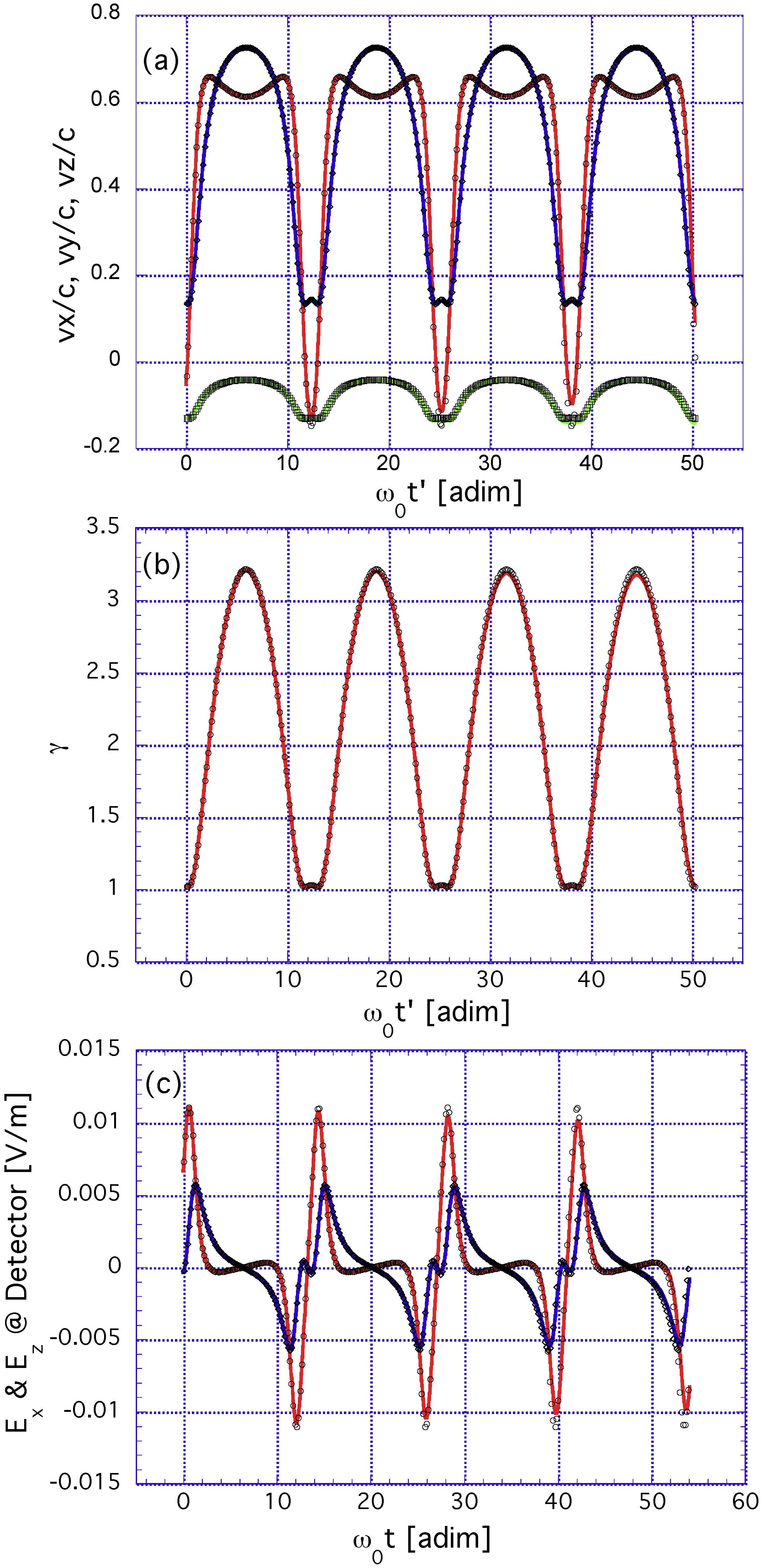
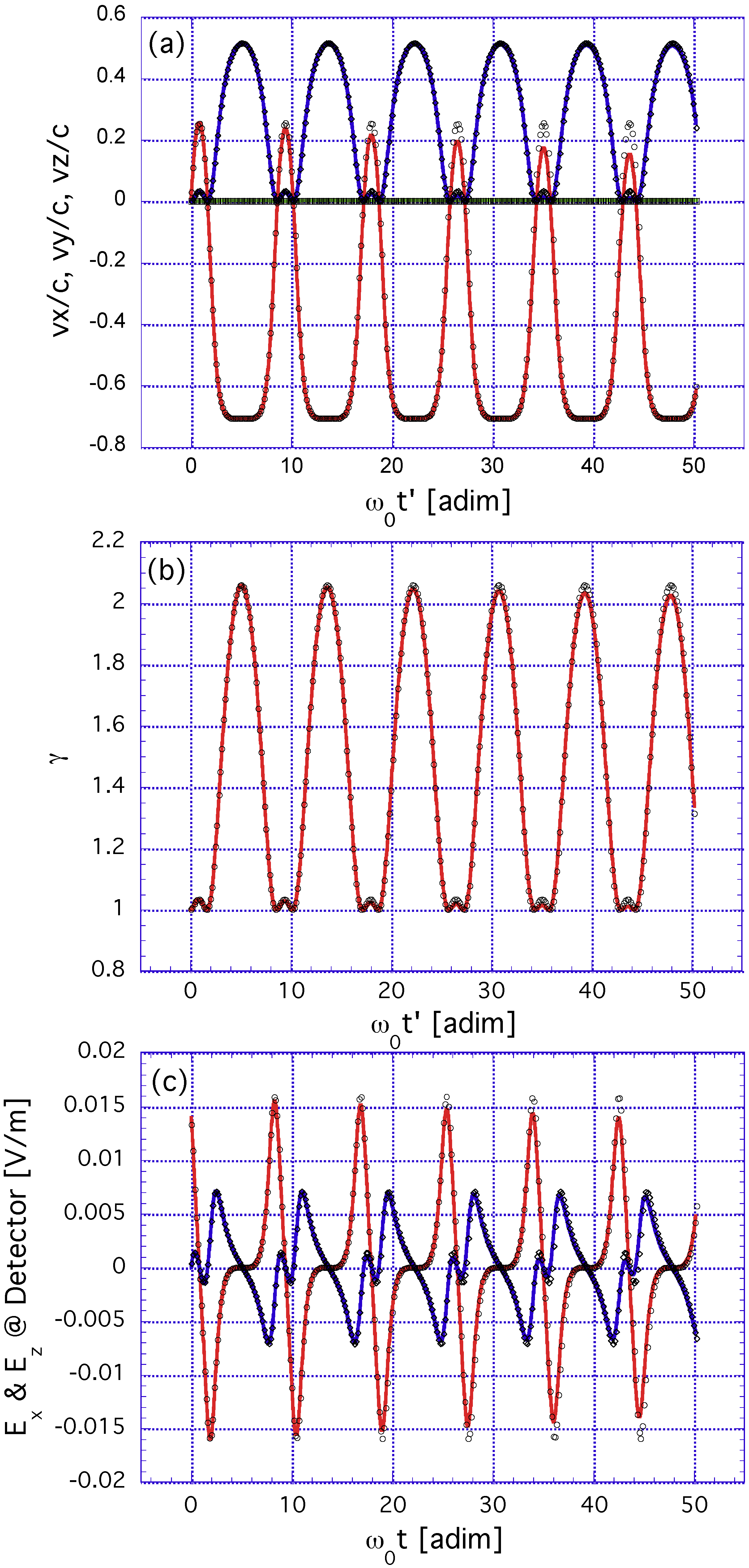
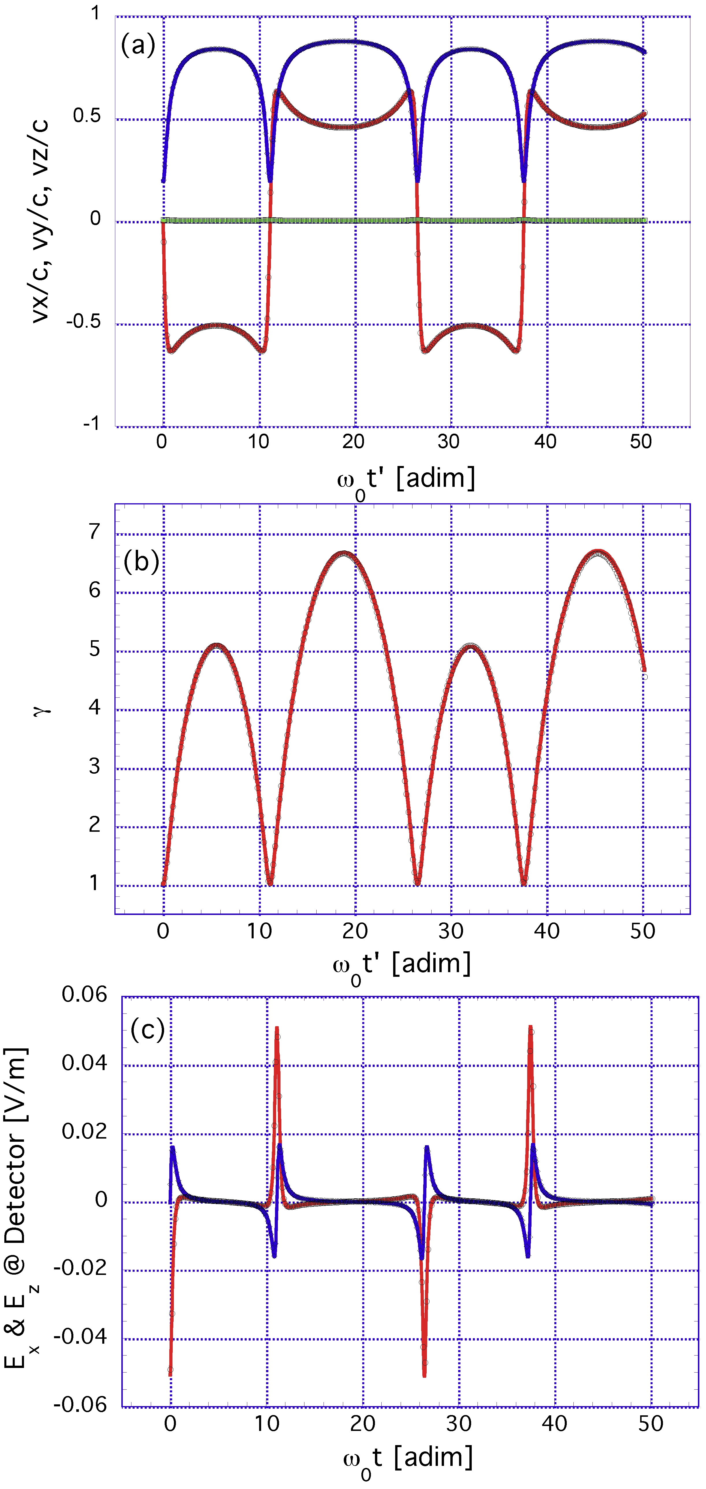
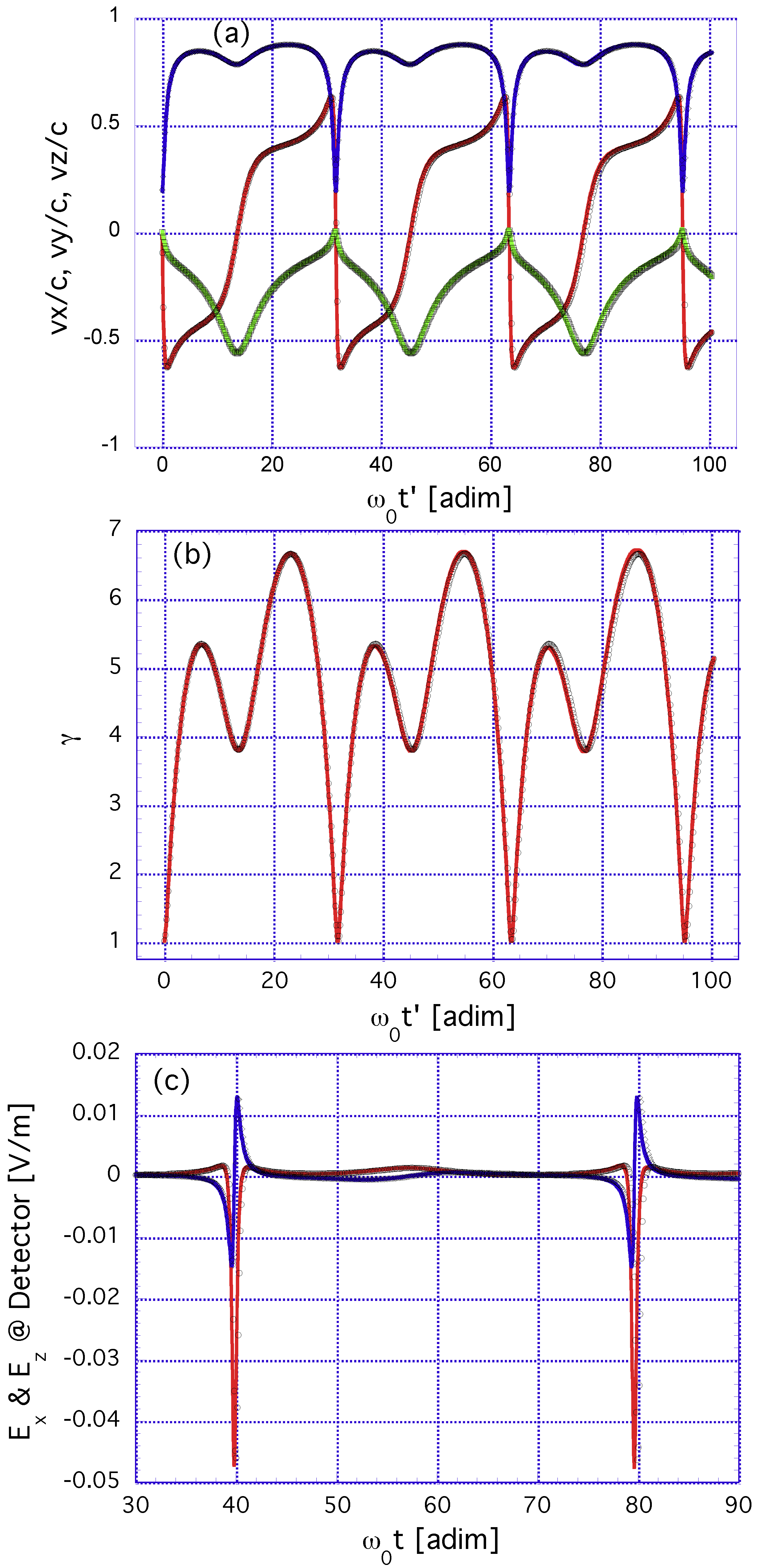
3. Elliptically Polarized Radiation: Parametric Representation of Dynamical Variables

3.1. Representation of an Arbitrary Non-Monochromatic Plane Wave through the Vector Potential  A i ( ξ )

The radiation (or Coulomb) gauge was employed. Let A i be the transverse vector potential of the incoming electric and magnetic fields E i and B i . E i , B i , and A i depend on a three-dimensional position y = ( y 1 , y 2 , y 3 ) and on time (t). One has in the radiation gauge:
y A i = 0 , E i = A i t , B i = y × A i .
Let the input beam field, corresponding to an arbitrary non-monochromatic plane wave and fulfilling the charge-free Maxwell equations in vacuum, propagate along the y 3 axis, from towards + . Then, A i ( y ; t ) = A i ( ξ ) , where ξ t y 3 / c , lies in the ( y 1 , y 2 ) -plane:
A i = ( A ¯ i , 0 ) , A ¯ i = A ¯ i ( ξ ) = ( A i 1 , A i 2 ) , E i = A i , B i = c 1 k × E i
with A i d A i / d ξ and k being the standard vector along the y 3 axis. Variables with overbars always denote two-dimensional vectors in the ( y 1 , y 2 ) -plane. A general case was considered in which β 0 is not necessarily orthogonal to A i , that is β 0 · A i = 0 was not imposed.
The exact analytical solution of Equation (1), with E i and B i describing a general non-monochromatic plane wave, was given in [27,28,29,30,31,32,33,35,36]. The general solutions of Equation (1), with those E i and B i , are x = ( x ¯ , x 3 ) = ( x 1 , x 2 , x 3 ) and p = ( p ¯ , p 3 ) = ( p 1 , p 2 , p 3 ) , which contain six suitable integration constants. The latter are: x ¯ 0 = ( x 10 , x 20 ) and x 30 (the three-dimensional vector determining the position of the electron at ξ = 0 ) and the other three variables ( f ¯ = ( f 1 , f 2 ) and γ 1 ) related to the initial momentum of the electron: [35,36]. The dimensionless γ ( t ) appearing in Equation (1) should not be confused with γ 1 .
The incoming electromagnetic field is described by unique electric and magnetic fields ( E i and B i ), and the dynamics and trajectory of the relativistic electron are also uniquely determined. On the other hand, the vector potential A i or A ¯ i is not unique: the transformation A ¯ i ( ξ ) A ¯ i ( ξ ) = A ¯ i ( ξ ) + δ A ¯ i , δ A ¯ i being ξ -independent, gives rise to the same E i and B i (gauge invariance of the electromagnetic field). The electron trajectory is independent of δ A ¯ i . See [36].

3.2. The Vector Potential and the Solution of the Electron Dynamics for Monochromatic Elliptically Polarized Radiation

The (real) electric field for a plane wave with elliptic polarization is given by:
E i = R e [ ( E 0 ϵ 1 + i E 1 ϵ 2 ) × exp i ( k 0 x 3 ω 0 t + φ 0 ) ] ,
where R e denotes the real part; the amplitudes E 0 , E 1 , the unit vectors ϵ 1 and ϵ 2 , and the phase φ 0 are all real. ϵ 1 and ϵ 2 are:
ϵ 1 = cos θ d i + sin θ d j , ϵ 2 = sin θ d i + cos θ d j .
θ d is a real angle that gives the orientation of the principal axes of the polarization ellipse with respect to the ( x , y ) axes. ω 0 (real and > 0 ) is the frequency. The vector potential, with ζ = ω 0 ξ , reads:
A i = A ¯ 0 1 ω 0 [ a ¯ c o sin ( ζ φ 0 ) + a ¯ s i cos ( ζ φ 0 ) ] ,
where a ¯ c o = E 0 ϵ 1 , a ¯ s i = E 1 ϵ 2 . Let:
c 1 = a ¯ c o 2 + a ¯ s i 2 = E 0 2 + E 1 2 ,
c 2 = a ¯ c o 2 a ¯ s i 2 = E 0 2 E 1 2 .
As an initial condition for A i , we always imposed that A i = 0 at ζ = ζ 0 (typically and without loss of generality, ζ 0 = 0 ). Then:
A ¯ 0 = 1 ω 0 [ a ¯ c o sin ( ζ 0 φ 0 ) + a ¯ s i cos ( ζ 0 φ 0 ) ] .
Notice that this is a particular choice of gauge; see [36]. The phase φ 0 has a physical meaning, and it is gauge-independent. Recall that the physical (gauge-independent) time-dependent momentum is p ¯ ( ξ ) = f ¯ e A ¯ i . Then, with the present gauge choice, the constant of motion f ¯ (gauge-dependent) coincides with the physical p ¯ ( ξ = 0 ) . x ¯ ( ξ ) , x 3 ( ξ ) , Λ ( ξ ) are gauge-independent.
We solved the equations of motion for the vector potential given by A i ( ξ ) by following [27]. The initial conditions for the electron coordinates are x 10 , x 20 , x 30 . The initial conditions for the electron momentum p 10 , p 20 , p 30 follow from the three integration constants f ¯ = ( f 1 , f 2 ) and γ 1 ; see [36]. Introducing ( x ˜ 1 = k 0 x 1 , and so on) and ( p ˜ 1 = p 1 / m c , and so on), we obtained:
x ˜ 1 ( ζ ) = x ˜ 10 + λ 1 l ( ζ ζ 0 ) + λ 1 c [ cos ( ζ φ 0 ) cos ( ζ 0 φ 0 ) ] + λ 1 s [ sin ( ζ φ 0 ) sin ( ζ 0 φ 0 ) ] ,
x ˜ 2 ( ζ ) = x ˜ 20 + λ 2 l ( ζ ζ 0 ) + λ 2 c [ cos ( ζ φ 0 ) cos ( ζ 0 φ 0 ) ] + λ 2 s [ sin ( ζ φ 0 ) sin ( ζ 0 φ 0 ) ] ,
x ˜ 3 ( ζ ) = x ˜ 30 + λ 3 l ( ζ ζ 0 ) + λ 3 c [ cos ( ζ φ 0 ) cos ( ζ 0 φ 0 ) ] + λ 3 s [ sin ( ζ φ 0 ) sin ( ζ 0 φ 0 ) ] + λ 3 s 2 [ sin ( 2 ( ζ φ 0 ) ) sin ( 2 ( ζ 0 φ 0 ) ) ] ,
and:
p ˜ 1 ( ζ ) = ( p ˜ 10 α A 01 ) + α E 0 cos θ d sin ( ζ φ 0 ) + α E 1 sin θ d cos ( ζ φ 0 ) ,
p ˜ 2 ( ζ ) = ( p ˜ 20 α A 02 ) + α E 0 sin θ d sin ( ζ φ 0 ) α E 1 cos θ d cos ( ζ φ 0 ) ,
p ˜ 3 ( ζ ) = ( 1 γ 1 n 2 + p ˜ 1 2 ( ζ ) + p ˜ 2 2 ( ζ ) ) / 2 γ 1 n .
The parameters appearing in the formulas above are given in Appendix A.
The Lorentz factor γ , the normalized velocity β = ( β 1 , β 2 , β 3 ) = v / c , and the acceleration a = ( a 1 , a 2 , a 3 ) = d v / d t can also be computed in closed form in terms of the parameter ζ , namely:
γ ( ζ ) = 1 + p ˜ 1 2 ( ζ ) + p ˜ 2 2 ( ζ ) + p ˜ 3 2 ( ζ ) ,
β 1 ( ζ ) = p ˜ 1 ( ζ ) / γ ( ζ ) ,
β 2 ( ζ ) = p ˜ 2 ( ζ ) / γ ( ζ ) ,
β 3 ( ζ ) = p ˜ 3 ( ζ ) / γ ( ζ ) .
a 1 = d v 1 / d t = c ( d β 1 / d ζ ) ( d ζ / d t ) = ω 0 c ( 1 β 3 ( ζ ) ) d β 1 / d ζ ,
a 2 = d v 2 / d t = c ( d β 2 / d ζ ) ( d ζ / d t ) = ω 0 c ( 1 β 3 ( ζ ) ) d β 2 / d ζ ,
a 3 = d v 3 / d t = c ( d β 3 / d ζ ) ( d ζ / d t ) = ω 0 c ( 1 β 3 ( ζ ) ) d β 3 / d ζ .
Coordinate time ( t ) and also the time at the detector (t) admit closed (although involved) expressions in terms of ζ : from:
ζ = ω 0 t k 0 x 3 ,
d ζ 1 β 3 ( ζ ) = ω 0 d t ,
m c γ ( ζ ) d ζ = ( γ 1 + p 3 ( ζ ) ) d ζ = γ 1 ω 0 d t ,
and performing the integration of the left-hand side of the last equation (which involves only elementary functions), t is obtained as an explicit function of ζ , namely:
ω 0 ( t t 0 ) = τ l ( ζ ζ 0 ) + τ c ( cos ( ζ φ 0 ) cos ( ζ 0 φ 0 ) ) + τ s ( sin ( ζ φ 0 ) sin ( ζ 0 φ 0 ) ) + τ 2 s ( sin ( 2 ( ζ φ 0 ) ) sin ( 2 ( ζ 0 φ 0 ) ) ) .
The differential relationship that connects trajectory time t and the time at the detector t (“detection” time) is given by d t = ( 1 n ) · β ) d t ; see [32,36]. Taking into account that in radiation problems, it is (in general) a very good approximation to put n = c o n s t a n t , n being a constant scattering vector, and making use of the differential relationship between d t and d ζ , one obtains after elementary transformations that:
( γ 1 + p 3 ( ζ ) n · p ( ζ ) ) d ζ = γ 1 ω 0 d t .
In this case, we considered a unit scattering vector n ( = ( n 1 , n 2 , n 3 ) = ( n ¯ , n 3 ) ) that is not lying necessarily in the ( y 1 , y 3 ) -plane, that being a generalization of the treatment presented in our previous paper [36]. The integration of the left-hand side of Equation (34) can also be carried out using elementary functions, and t is also an explicit function of ζ :
ω 0 ( t t 0 ) = τ l ( ζ ζ 0 ) + τ c ( cos ( ζ φ 0 ) cos ( ζ 0 φ 0 ) ) + τ s ( sin ( ζ φ 0 ) sin ( ζ 0 φ 0 ) ) + τ 2 s ( sin ( 2 ( ζ φ 0 ) ) sin ( 2 ( ζ 0 φ 0 ) ) ) .
The coefficients τ l , τ c , τ s , τ 2 s , τ l , τ c , τ s , τ 2 s are given in Appendix A. t 0 and t 0 are integration constants that satisfy t = t 0 and t = t 0 at ζ = ζ 0 .
All this algebraic machinery allows also obtaining explicit formulas for the Liénard–Wiechert radiated fields at the detector, using their definition from Equations (2) and (3), with all the variables as functions of the parameter ζ . The parametric formulas, together with the relationship between ζ and t already mentioned, allow for a complete description of Liénard–Wiechert fields in the time domain in a computationally very efficient way. This representation is the counterpart to the frequency domain representation that will be dealt with in the next section and contains, of course, the same information.

3.3. Magnitudes Derived from the Parametric Representation of Trajectories

The parametric representation of dynamics obtained in the previous subsection allows for an analytical computation of several quantities of interest associated with the trajectory in a rather straightforward manner, namely the fundamental period/frequency of the trajectory, the fundamental period/frequency at detector position, the drift velocity (defined as the velocity at which the particle is at rest on average), the extremal values for the momentum components and the γ factor. From (33) and (35) and taking two ζ values 2 π apart from each other, one obtains for the fundamental period of the trajectory, the fundamental period, and the fundamental frequency ( ω f = 2 π / T f ) at the detector the expressions:
τ f = ω 0 T f = 2 π τ l ,
Ω f = ( ω f / ω 0 ) = 1 / τ l .
Due to the relevance of Ω f in nonlinear TS problems, let us write it down explicitly as:
Ω f = 1 1 n ¯ ( f ¯ e A ¯ 0 ) γ 1 + ( 1 n 3 ) ( s c + e 2 c 1 4 ω 0 2 γ 1 2 e f ¯ A ¯ 0 γ 1 2 + e 2 A ¯ 0 2 2 γ 1 2 ) .
In this form, the dependencies of Ω f on the initial momentum (through f ¯ , s / c , γ 1 ), the scattering vector (through n ), and the parameters characterizing the laser ( c 1 , A ¯ 0 ) are apparent. Since A ¯ 0 depends on the initial phase of the laser field φ 0 , the fundamental Thomson scattering frequency also depends on it in the high intensity regime. It is clear that this dependency on the phase is absent if A ¯ 0 vanishes; moreover, if c 1 and A ¯ 0 vanish or are very small (the case of a low-intensity laser), one recovers the standard Doppler frequency. The dependency of Ω f on several kinematical (i.e., associated with the initial position and the initial momentum of electron) and laser parameters (intensity, polarization, helicity) makes it possible (to some extent) to select the frequency at an specific detection point, that is an engineering of the radiated spectrum seems feasible by a judicious choice of the control parameters. Let us illustrate this in Figure 1 with a simple example with the following setup. In the upper panel, the electron is initially at the origin of the coordinates with E k i n 0 = 0 . The reference electric field of the incoming laser is chosen E r = 5.0 × 10 12 V/m. E 0 , E 1 are defined from E r and the angle θ s as E 0 = E r cos θ s , E 1 = E r sin θ s . In the lower panel, E k i n 0 = 200.0 keV, and the angles giving the orientation of the initial momentum are θ = π / 2 , φ = π / 4 ; the laser parameters are the same. The point at which the scattered radiation is measured was assumed to lie 0.5 m along the positive direction of the y axis. The opportunities for scattered frequency engineering are clearly displayed in the two panels, by playing with either kinematical or laser parameters, including, in a non-trivial way, the dependency on the initial phase ( φ 0 ) and the polarization/helicity of the laser beam. Please, note that in the figures of the paper, “adim.” stands for “adimensional”, meaning a magnitude with no dimensions, i.e., a pure number.
The fundamental period ( T f u n d ) of the trajectory (and hence, its fundamental frequency) also has a non-trivial dependency on φ 0 and the laser polarization state, inherited from the parameters τ l , τ c , τ s and τ 2 s . This is shown (Figure 2) in a case where the laser has a reference peak electric field of E r = 4.257 × 10 12 V/m, E 0 = E r cos θ s , E 1 = E r sin θ s , and the electron has an initial kinetic energy of E k i n 0 = 10.0 keV, its initial velocity being oriented with respect to the laser propagation direction ( z axis) at angles θ = 0.807433 , φ = 4.32799 . Three different polarizations corresponding to θ s = 0 , θ s = ± π / 4 , θ s = ± π / 8 are displayed. The vertical axis of this figure, labeled as “Fundamental Period (adim.)”, is defined as ω 0 × T f u n d .
The important question of the field amplitudes (and hence, the power) associated with the different frequency components at the detector, i.e., the Thomson scattering spectrum, is perhaps more conveniently addressed in the frequency domain and shall be dealt with in the next section.
The drift velocity, defined as the average velocity over a fundamental period of trajectory, β 1 , a v = < β 1 ( t ) > = 1 T f t 0 t 0 + T f β 1 ( t ) d t , etc., is obtained after an elementary change of variables from t to ζ as:
β 1 , a v = 1 2 π γ 1 τ l ζ 0 ζ 0 + 2 π p 1 ( ζ ) d ζ ,
β 2 , a v = 1 2 π γ 1 τ l ζ 0 ζ 0 + 2 π p 2 ( ζ ) d ζ ,
β 3 , a v = 1 2 π γ 1 τ l ζ 0 ζ 0 + 2 π p 3 ( ζ ) d ζ .
Explicit formulas for β 1 , a v , β 2 , a v , β 3 , a v are given in Appendix A. Figure 3 shows (in an exemplary case) how a transformation to the Lorentz frame with the drift velocity allows obtaining for x 1 vs. x 3 a shape reminiscent of the “figure of eight” shape as mentioned for example in [27,28]. x 1 and x 3 are the Lorentz-transformed coordinates corresponding to x 1 , x 3 under the boost with the drift velocity ( c β 1 , a v , c β 2 , a v , c β 3 , a v ) . The parameters used in this case are E r = 4.257 × 10 12 V/m, θ s = 0 , φ 0 = 3.57517 , E k i n 0 = 10.0 keV, θ = 0.807433 , φ = 4.32799 .
Extremal values for momentum and relativistic γ factor can easily be obtained from d p / d t = ( d p / d ζ ) ( d ζ / d t ) = ω 0 ( 1 β 3 ) d p / d ζ = 0 , d γ / d t = ( d γ / d ζ ) ( d ζ / d t ) = ω 0 ( 1 β 3 ) d γ / d ζ = 0 and the fact that ( 1 β 3 ) is never equal to zero. Hence, extremal values for momentum components are obtained from:
d p 1 / d ζ = 0 α E 0 cos θ d cos ( ζ e ζ 0 ) = α E 1 sin θ d sin ( ζ e ζ 0 ) ,
d p 2 / d ζ = 0 α E 0 sin θ d cos ( ζ e ζ 0 ) = α E 1 cos θ d sin ( ζ e ζ 0 ) ,
d p 3 / d ζ = 0 p 1 d p 1 / d ζ + p 2 d p 2 / d ζ = 0 .
The equations for p 1 , p 2 extremal values are easily solved; the one for the extremal values of p 3 or γ (which are the same due to the relationship m c γ = γ 1 + p 3 , γ 1 constant) is slightly more involved, but it is nevertheless amenable to efficient numerical computation. As an example, the non-trivial dependency of the maximum of γ factor on φ 0 is shown in Figure 4, where, for the same conditions as mentioned for Figure 2, the initial phase of the laser beam is systematically varied in the interval [ π , π ] .

4. Spectral Representation for Elliptically Polarized Incoming Radiation: The Integrand and Doppler Frequencies

We replaced the general solution in Equations (17)–(19) for elliptic polarization into Λ ( ξ ) = Λ ( ξ ) E (which is gauge-independent). We kept the same integration constants f 1 , f 2 , γ 1 , x 10 , x 20 , and x 30 . Let φ 0 + 3 π / 2 = φ 1 and n = ( n ¯ , n 3 ) .
We omitted a lengthy analytical computation. We found for Λ ( ξ ) E :
Λ ( ξ ) E = 1 ω 0 [ g 0 , E + g 1 , E ω 0 ξ + g 2 , E sin ( ω 0 ξ φ 1 + φ 1 s , E ) g 3 , E sin 2 ( ω 0 ξ φ 1 + φ 2 s , E ) ]
g 0 , E ω 0 = g 0 , 1 ω 0 + g 0 , 2 ω 0 + g 0 , 3 ω 0 + g 0 , 4 ω 0
g 0 , 1 ω 0 = 1 n 3 c [ x 30 c e γ 1 2 ω 0 2 f ¯ ( a ¯ c o sin φ 1 a ¯ s i cos φ 1 ) ]
g 0 , 2 ω 0 = ( 1 n 3 ) e 2 c 2 sin 2 φ 1 8 γ 1 2 ω 0 3
g 0 , 3 ω 0 = n ¯ c [ x ¯ 0 c e γ 1 ω 0 2 ( a ¯ c o sin φ 1 a ¯ s i cos φ 1 ) ]
g 0 , 4 ω 0 = ( 1 n 3 ) e 2 γ 1 2 ω 0 2 A ¯ 0 ( a ¯ c o sin φ 1 a ¯ s i cos φ 1 )
g 1 , E = 1 n ¯ ( f ¯ e A ¯ 0 ) γ 1 + ( 1 n 3 ) ( s c + e 2 c 1 4 ω 0 2 γ 1 2 e f ¯ A ¯ 0 γ 1 2 + e 2 A ¯ 0 2 2 γ 1 2 )
g 2 , E cos φ 1 s , E ω 0 = ( 1 n 3 ) ( e f ¯ a ¯ c o + e 2 A ¯ 0 a ¯ c o ) γ 1 2 ω 0 2 + e n ¯ a ¯ c o γ 1 ω 0 2
g 2 , E sin φ 1 s , E ω 0 = ( 1 n 3 ) ( e f ¯ a ¯ s i + e 2 A ¯ 0 a ¯ s i ) γ 1 2 ω 0 2 + e n ¯ a ¯ s i γ 1 ω 0 2
g 3 , E cos 2 φ 2 s , E ω 0 = ( 1 n 3 ) e 2 c 2 8 γ 1 2 ω 0 3
g 3 , E sin 2 φ 2 s , E ω 0 = 0
All g n , E ’s are gauge-independent. The parameter s was defined in [36]. With the definitions given above, the coefficients g n , E , n = 0 , 1 , 2 , 3 are dimensionless. The treatment given here includes the cases in which β 0 · A i may be = 0 or 0 .
In order to compute p ˜ ( y , ω ) for elliptic polarization, let us introduce the following scalar functions ( n = 0 , ± 1 , ± 2 ):
b n , E = + d ξ ( 2 π ) 1 / 2 exp [ i ω Λ ( ξ ) E + i n ω 0 ξ ] .
Notice that b n , E ( ω ) = [ b n , E ( ω ) ] * , where ∗ denotes the complex conjugate. p ˜ ( y , ω ) = p ˜ ( y , ω ) = ( p ˜ 1 , p ˜ 2 , p ˜ 3 ) can be expressed in terms of the scalar b n , E ’s.
Let:
x = ω g 2 , E ω 0 , y = ω g 3 , E ω 0 .
We considered the generating function:
exp ( i [ x sin ( ω 0 ξ φ 1 + φ 1 s , E ) y sin 2 ( ω 0 ξ φ 1 + φ 2 s , E ) ] ) = l = + J G , l ( x , y ; φ 2 s , E φ 1 s , E ) exp [ i l ( ω 0 ξ φ 1 + φ 2 s , E ) ] .
J G , l ( x , y ; φ 2 s , E φ 1 s , E ) is a generalization of the generalized Bessel functions J l ( x , y ) . For an account of the latter, see [36,39] and the references therein. Some properties of J G , l ( x , y ; φ 2 s , E φ 1 s , E ) will be given in Appendix B. J G , l ( x , y ; φ 2 s , E φ 1 s , E ) is a complex function.
By plugging Equation (59) into b n , E , one finds ( ω r = ω / ω 0 ):
b n , E = ( 2 π ) 1 / 2 ω 0 exp ( i ω r g 0 , E ) × l = + J G , l n ( ω r g 2 , E , ω r g 3 , E ; φ 2 s , E φ 1 s , E ) × exp [ i ( l + n ) ( φ 1 φ 2 s , E ) ] δ ( ω r g 1 , E l ) ,
δ denoting now the Dirac delta function.
The generalized Doppler-like formula for elliptic polarization reads:
ω l = l ω 0 g 1 , E = l ω 0 1 n ¯ ( f ¯ e A ¯ 0 ) γ 1 + ( 1 n 3 ) ( s c + e 2 c 1 4 ω 0 2 γ 1 2 + e 2 A ¯ 0 2 2 γ 1 2 e f ¯ A ¯ 0 γ 1 2 ) ,
for the given g 1 , E and for all the integers l ( = 0 , ± 1 , ± 2 , ± 3 , ). Of course, ω l / ω 0 for l = 1 from Equation (61) (treatment in the frequency domain) equals Ω f in Equation (39) (treatment in the time domain).

5. TS for an Incoming Laser Beam with OAM

5.1. Incoming Laser Beam with OAM: Vector Potential and Electromagnetic Fields

The input beam field was chosen to be an electromagnetic wave in vacuum that propagates along the z axis, from towards + , and corresponds to a Gauss–Laguerre mode in the ( x , y ) -plane and, so, having some given orbital angular momentum (OAM). The fields of the OAM mode are not strictly transverse: they have small components in the direction of propagation (namely, the z axis). See [6,16,40]. The radiation (or Coulomb) gauge will be employed. Let A i be the vector potential of the incoming electric ( E i ) and magnetic ( B i ) fields. E i , B i , and A i depend on a three-dimensional position y = ( x , y , z ) and on time (t). Equation (9) continues to hold in the radiation gauge. By assumption, the (real) vector potential A i lies in the ( x , y ) -plane (namely, the ( y 1 , y 2 ) -plane): A i ( y ; t ) = A x i + A y j , with:
A x = η 0 A 0 L G l , p ( ρ , z ) exp i ψ + c . c .
A y = η 1 A 0 L G l , p ( ρ , z ) exp i ψ + c . c .
As usual, c.c. denotes the complex conjugate of the preceding term. A 0 is a real amplitude, ρ = ( x 2 + y 2 ) 1 / 2 . η 0 and η 1 are complex numbers, with η 0 2 + η 1 2 = 1 . We write:
η 0 = π 0 + i π 1 ,
η 1 = σ 0 + i σ 1 .
π 0 , π 1 , σ 0 , and σ 1 are real constants fulfilling the condition π 0 2 + π 1 2 + σ 0 2 + σ 1 2 = 1 and describing the polarization state of the field. Although we concentrated on the case of an incoming laser beam linearly polarized along the x axis, other polarization states can be treated as well by a suitable selection of π 0 , π 1 , σ 0 , and σ 1 . The Laguerre–Gauss (LG) functions L G l , p ( ρ , z ) are given in Appendix D. On the other hand:
ψ = k 0 z ω 0 t + χ 0 + l ϕ + k 0 ρ 2 2 R ( z ) + ϕ G ( z ) ,
1 R ( z ) = r ( z ) = z z 2 + z 0 2 ,
ϕ G ( z ) = ( 2 p + l + 1 ) arctan ( z / z 0 ) ,
with ϕ = arctan ( y / x ) . χ 0 is a constant phase. w 0 is the beam-waist parameter. z 0 is the Rayleigh range, defined by z 0 = k 0 w 0 2 / 2 with k 0 = 2 π / λ 0 . ω 0 (real and > 0 ) is the frequency, and ω 0 = k 0 c .
For an incoming laser beam linearly polarized along the x axis, one has π 1 = σ 0 = σ 1 = 0 and E y = 0 for any t, ( x , y , z ) . Then, A y = 0 , B x = 0 , while E x , B y , and B z are non-vanishing.

5.2. Approximating the Electron Dynamics in OAM Beams by the Plane-Wave Solution: Numerical Computations

One of the reasons to study in depth the plane-wave solution, as performed in previous sections, is of course to generalize previous results, including the most general state of polarization for this type of wave (i.e., elliptical polarization) and the non-trivial initial phase dependency of dynamical variables. Another important reason is to provide a tool for the approximate analytical (or semi-analytical) treatment of more complex laser beams, like the ones with OAM, where one has to (heavily) rely on numerical computations to obtain an understanding of their dynamics. See [16] for a description and implementation of the numerical methods used to characterize the electron dynamics and the ensuing Thomson scattering emission in laser beams with OAM.
The rule that has been found to apply to obtain a good fit between OAM and plane-wave solution is as follows. From the characteristics of the OAM beam and the initial position of the electron, compute the local values of the laser parameter and phase, namely α l o c a l = 2 A 0 L G l , p ( x 10 , x 20 , x 30 ) / ( m c ) and ψ l o c a l = ψ ( x 10 , x 20 , x 30 , t 0 ) . Introduce these values in the plane-wave solution with the same polarization state as the OAM wave and use the same initial electron kinetic energy and the same values for the angles θ , φ .
By means of the examples to follow, we claimed here that the plane-wave solutions for the dynamics of the electron can be, in some instances to be described, a very good fit to the actual dynamics in beams with OAM. The conditions to be met for the fitting are basically (i) that local values for the adimensional laser parameter and phase are chosen in OAM, and put into the plane-wave solution, (ii) that the transverse excursion of the electron is not too large, and (iii) that the dynamics is studied for a limited number of optical cycles. If these conditions are met, the plane-wave solution can fit OAM solutions to a high degree of precision for a wide range of parameters in electron energy, laser intensity, or polarization.
The electron dynamics was computed in an OAM laser beam having the following parameters: λ 0 = 800 nm, w 0 = 100 m, χ 0 = 0 , ( l , p ) = ( 1 , 0 ) , A 0 ranging from 2.5 × 10 3 V·s/m to 7.5 × 10 3 V·s/m. Polarization, if not otherwise stated, was linear along the x axis. Electrons with initial kinetic energy ranging from zero to 100 keV were studied; their initial positions were randomly chosen in the intervals x 10 [ w 0 , w 0 ] , x 20 [ w 0 , w 0 ] , x 30 [ λ 0 / 2 , λ 0 / 2 ] . Polar ( θ ) and azimuthal ( φ ) angles giving the initial momentum direction (with respect to the z axis or laser propagation direction) were randomly chosen in the intervals [ 0 , π ] , [ 0 , 2 π ] . In Figure 5, Figure 6, Figure 7, Figure 8 and Figure 9, the color code is as follows: red, green, and blue colors are assigned to the x-, y-, or z-component of the corresponding magnitude (in the case of vector quantities). For example, the x-component of velocity will be assigned red color in the figures or the z-component of the radiated electric field will be assigned blue color, etc.
Figure 5 shows the comparison of normalized velocity components, the γ factor, and the radiated E field at the detector (two orthogonal quadratures along the x and z axes). The parameters were A 0 = 2.5 × 10 3 V·s/m (OAM beam), E k i n 0 = 10.0 keV, x 10 = 98.4242 μm, x 20 = 52.9688 μm, x 30 = 3.57517 μm; θ = 0.807433 , φ = 4.32799 . It can be seen that the fitting was quite good in this example, and a simple measure of it can be obtained if maximum values of the γ factor are compared: the maximum of γ O A M = 3.213 vs. the maximum of γ p l a n e = 3.216 , i.e., a relative difference of less than 10 3 . It is clear that radiated spectra will be very similar due to the similarity of radiated fields at the detector in the time domain, although no systematic comparison is this connection was attempted in this paper.
A second example is shown (Figure 6) in which A 0 = 2.5 × 10 3 V·s/m (OAM beam), E k i n 0 = 0.0 keV, x 10 = 28.0601 μm, x 20 = 1.38741 μm, x 30 = 0.108658 μm. In this case, some drift was apparent in the velocity of the OAM solution; hence, the fitting was not perfect, since the plane-wave solution simply cannot capture the changes induced by large variations in the transverse profile of the OAM mode. It was nevertheless an overall good fit for a limited section of the trajectory, some of its main characteristics being captured by the more simple plane-wave solution.
Figure 7 shows a case in which A 0 = 5.0 × 10 3 V·s/m (OAM beam), E k i n 0 = 10.0 keV, x 10 = 71.0055 μm, x 20 = 30.9694 μm, x 30 = 0.262421 μm, θ = 0.0433 , φ = 0.6058 . The plane-wave solution closely fits the OAM solution in this case, which showed a large excursion of the relativistic γ factor, up to nearly seven. The maximum value of γ O A M = 6.70 should be compared with the maximum of γ p l a n e = 6.66 , i.e., a relative difference of less than 6.0 × 10 3 .
To end this relation of comparative studies between the dynamics and radiated fields in laser beams with OAM and the corresponding analytical solution, let us present a case in which the OAM beam has a genuine elliptical polarization state, characterized by ( π 0 , π 1 , σ 0 , σ 1 ) = ( cos π / 8 , 0 , 0 , sin π / 8 ) , and compare it with the corresponding elliptically polarized analytical solution (Figure 8). The rest of the parameters in the comparison were the same as in Figure 7. The match of OAM vs. the analytical solution was also very good here, showing the ability of these extended solutions to also cover the case of complex OAM beams with arbitrary (in particular, genuine elliptical) polarization.
A simple quantitative estimation of the conditions in which a good match between OAM and plane-wave solutions is expected is as follows: if the transverse excursion of the electron during the integration time for a particular trajectory is much less than the size of the OAM laser beam w 0 , a good match is expected. The reason would be that in that case, the transverse variation of the laser intensity is less important than the fact that the local OAM laser field can always be faithfully fitted by a plane wave of adequate intensity, phase, and polarization. In formulas:
c β 1 , a v 2 + β 2 , a v 2 T i n t < < w 0 ,
c β 1 , a v 2 + β 2 , a v 2 2 π N c y c l e s / ω 0 < < w 0 ,
N c y c l e s β 1 , a v 2 + β 2 , a v 2 < < w 0 / λ 0 ,
where T i n t = 2 π N c y c l e s / ω 0 means the integration time of the trajectory, β 1 , a v and β 2 , a v are the transverse components of the drift velocity (as obtained from the plane-wave solution), w 0 sets the transverse spatial scale of the OAM beam ( w 0 = 100.0 μm is used throughout this section), and λ 0 is the laser wavelength, equal to 800.0 nm in our case.
In the course of the investigations reported here, a new feature was noticed in very long integrations (involving several hundreds of optical cycles). In such a case and for OAM beams with ( l , p ) = ( 1 , 0 ) , we observed trajectories that perform a finite, i.e., not drifting, movement in the transverse X-Y plane, while they acquired some net drift velocity in the Z-direction. We provisionally named them as trapped trajectories or solutions. They typically appeared if the initial conditions in the transverse direction were close to the beam center and were found not only for E k i n 0 = 0 , but also for a substantial range of initial kinetic energy. The character of the dynamics was not easy to ascertain, but evidence from Fourier analysis was compatible with a quasi-periodic motion involving combinations of close, but incommensurate frequencies. A specific challenge to study these solutions is that the integration must cope with both fast and slow time scales, the finite transverse motion being typically 100 times slower than the optical frequency. Figure 9 shows an example in which 512 optical cycles were integrated with the following initial conditions for the electron and the OAM beam: x 10 = 1.03196 μm, x 20 = −4.82347 μm, x 30 = −0.107291 μm, E k i n 0 = 2.5 keV, initial velocity along the positive x axis direction; ( l , p ) = ( 1 , 0 ) , λ 0 = 800.0 nm, w 0 = 100.0 μm, χ 0 = 0, A 0 = 5.0 × 10 3 V·s/m, the laser beam linearly polarized along the x axis. Please note that Figure 9 represents just a particular case and that the relative amplitude and phase of the X and Y components and the z axis drift shown in it can substantially change with the initial condition, the initial velocity, and the laser parameters. There is ongoing research to more fully characterize this kind of solution, which seems to go beyond the theoretical framework developed in this paper and which poses some numerical and theoretical challenges to their understanding.

6. Conclusions and Final Comments

Regarding the interrelated research Items (a) and (b) stated in the Abstract, the following results were obtained.
(a) The classical nonlinear incoherent TS from a single relativistic electron with an incoming plane wave monochromatic laser radiation with frequency ω 0 , wave vector k 0 , initial phase φ 0 , elliptical polarization, and any intensity was investigated analytically and numerically. A complete explicit solution in terms of the parameter ζ = ω 0 t k 0 z and with full account of the non-trivial influence of φ 0 0 in dynamical variables, and hence in the scattered spectrum, was given. In particular, the cases of TS with linear and circular polarizations and φ 0 0 were treated, thereby extending previous studies [36] for φ 0 = 0 .
In so doing, we also carried out a detailed comparison in the TS framework between the analytical solution and ab initio numerical solutions of the Lorentz relativistic equation. Specifically, in Equations (5)–(7), we used successively the analytical solution and the numerical solution: an excellent match was found between both approaches. This contributes to confirming the reliability of Equations (5)–(7) when ab initio numerical solutions are fed in.
Detailed formulas were provided for the fundamental TS (Doppler) frequency for a general scattering vector, with full account of the influence of the laser intensity, polarization, and initial phase φ 0 . The dependences of TS frequency on the kinematical and laser parameters (in particular, on φ 0 ) were displayed as a means to engineer the scattered spectrum. The explicit solutions for general elliptic polarization gave rise to very efficient computations of the electron TS Doppler frequencies, the period of trajectories, the drift velocities and relativistic factors for electrons, etc., with potential interest for TS in fusion plasmas. The dependences on φ 0 are displayed in Figure 1 (electron TS Doppler frequencies for linear, circular, and elliptical polarizations), Figure 2 (periods of electron trajectories for linear, circular, and elliptical polarizations), Figure 3 (electron drift velocities), and Figure 4 (electron relativistic factor).
(b) The analytical results for incoming plane-wave radiations obtained in this paper were successfully employed to approximate (for the sake of a tentative understanding) TS for the more complex laser beams with intrinsic orbital angular momentum (OAM). Previous numerical TS results for such beams [16] and new and extended numerical computations for them were used. The results were compared with the ones for the analytical solutions with plane waves presented here. They were found to be in very good agreement with each other for time spans of several optical cycles, provided that the local laser parameter and the local phase read from the OAM beam were used in the analytical solution. This agreement was shown to hold for a wide range of laser intensities, electron energies, and for several polarization states (Figure 5, Figure 6 and Figure 7), in particular and specifically for genuine elliptical polarization (Figure 8). We also analyzed and stressed the non-trivial role played by the initial phase φ 0 on several dynamical variables and in the scattered spectrum. According to the results presented in the paper, the local phase of the OAM laser beams and the local (transverse) variation of the laser intensity explained to a large extent the scattering spectra computed and discussed in [16].
The two cases considered in the paper are of growing current interest: amplifying mechanisms leading to petawatt peak powers generate linearly polarized laser fields in most cases. That explains why, so far, most of the research has been on such a polarization state or in the case of circular polarization, although at ultrahigh intensities, circular polarization is difficult to achieve. However, in many cases, the mirrors of the beam transport from compressor to target can induce some degree of elliptical polarization (intentional or not). Therefore, the present model describing an arbitrary degree of polarization can be of broad interest to model future experiments. On the other hand, there is a growing interest in OAM beams because of the new possibilities they bring. Until recently, ultra-intense OAM beams were considered very difficult to achieve; however, it has been shown that off-axis spiral phase mirrors can produce vortex beams of extremely high intensity, so the interest in those beams in the ultrahigh frontier is growing quickly, and the present model can be of relevance for the understanding of some features of those experiments as well.
A new feature was observed, for OAM beams with ( l , p ) = ( 1 , 0 ) , in very long integrations (involving several hundreds of optical cycles). Specifically, we found trajectories that perform a finite, i.e., not drifting, movement in the transverse X-Y plane, while they acquire some net drift velocity in the Z-direction. See Figure 9. Such trajectories typically appeared if the initial conditions in the transverse direction were close to the beam center and were found not only for E k i n 0 = 0 , but for a substantial range of initial kinetic energy.
For TS with an incoming plane-wave radiation with elliptical polarization, the analytical expressions obtained for the scattered spectrum were given in terms of infinite series of new generalizations of the standard Bessel function. Such new generalizations (so far unknown and, hence, not previously reported, to the best of our knowledge) constitute an extension of the already known generalized Bessel functions [39].
Finally, it is perhaps worth saying that petawatt lasers are a reality (both for shot pulses, femtoseconds, and for long pulses, picoseconds) and that multi-petawatt lasers are expected to be fully operative in a few years. Therefore, the results of the paper dealt with a realistic experimental situation. OAM beams are easily obtained from those lasers, using for example off-axis spiral phase mirrors; see for example [15]. Off-axis spiral mirrors of more than 10 cm in diameter and with high precision in the phase exist now. The technique is quite promising, and larger spiral phase mirrors are in construction; therefore, the study of the dynamics of electrons driven by such intense OAM beams can be of high interest.

Author Contributions

Conceptualization, I.P., R.F.Á.-E., L.R.; methodology, I.P., R.F.Á.-E., L.R., J.G. and F.C.; software, I.P.; validation, I.P., R.F.Á.-E., L.R.; formal analysis, R.F.Á.-E.; investigation, I.P., R.F.Á.-E., L.R., J.G. and F.C.; writing—original draft preparation, I.P., R.F.Á.-E., L.R.; writing—review and editing, I.P. All authors have read and agreed to the published version of the manuscript.

Funding

This research received no external funding.

Institutional Review Board Statement

Not applicable.

Informed Consent Statement

Not applicable.

Data Availability Statement

Numerical data supporting this research can be obtained from the corresponding author upon reasonable request.

Acknowledgments

I.P. acknowledges support from Ministerio de Ciencia, Innovación y Universidades (Spain) under Projects RTI2018-100835-B-I00 and RTI2018-096967-B-I00. R.F.Á.-E. acknowledges support from Ministerio de Ciencia, Innovación y Universidades (Spain) under Project PGC2018-094684-B-C21 (contract partially funded by FEDER). L.R. acknowledges support from Ministerio de Ciencia, Innovación y Universidades (Spain) through the PALMA Grant No. FIS2016-81056-R, from LaserLab Europe V Grant No. 871124, and from Junta de Castilla y León Grant No. CLP087U16. R.F.Á.-E. and F.C. are associate members of Instituto de Biocomputación y Física de los Sistemas Complejos, Universidad de Zaragoza, Zaragoza, Spain.

Conflicts of Interest

The authors declare no conflict of interest.

Appendix A. Miscellaneous Symbol Definitions and Formulas

We introduce the following definitions:
x ˜ 1 = k 0 x 1 ,
x ˜ 2 = k 0 x 2 ,
x ˜ 3 = k 0 x 3 ,
x ˜ 10 = k 0 x 10 ,
x ˜ 20 = k 0 x 20 ,
x ˜ 30 = k 0 x 30 ,
p ˜ 1 = p 1 / m c ,
p ˜ 2 = p 2 / m c ,
p ˜ 3 = p 3 / m c ,
p ˜ 10 = p 10 / m c ,
p ˜ 20 = p 20 / m c ,
p ˜ 30 = p 30 / m c ,
f 1 n = f 1 / m c = p ˜ 10 ,
f 2 n = f 2 / m c = p ˜ 20 ,
s = c p 30 / γ 1 ,
s n = s / c ,
γ 1 n = γ 1 / m c ,
α A 01 = q A 01 / m c ,
α A 02 = q A 02 / m c ,
E 0 = E r cos θ s ,
E 1 = E r sin θ s ,
α E 0 = q E 0 / ω 0 m c ,
α E 1 = q E 1 / ω 0 m c .
λ 1 l = ( p ˜ 10 α A 01 ) / γ 1 n ,
λ 1 c = α E 0 cos θ d / γ 1 n ,
λ 1 s = α E 1 sin θ d / γ 1 n ,
λ 2 l = ( p ˜ 20 α A 02 ) / γ 1 n ,
λ 2 c = α E 0 sin θ d / γ 1 n ,
λ 2 s = α E 1 cos θ d / γ 1 n ,
λ 3 l = s n ( f 1 n α A 01 + f 2 n α A 02 ) / γ 1 n 2 + ( α E 0 2 + α E 1 2 + 2 [ α A 01 2 + α A 02 2 ] ) / 4 γ 1 n 2 ,
λ 3 c = α E 0 ( [ p ˜ 10 α A 01 ] cos θ d + [ p ˜ 20 α A 02 ] sin θ d ) / γ 1 n 2 ,
λ 3 s = α E 1 ( [ p ˜ 10 α A 01 ] sin θ d [ p ˜ 20 α A 02 ] cos θ d ) / γ 1 n 2 ,
λ 3 s 2 = ( α E 0 2 α E 1 2 ) / 8 γ 1 n 2 .
τ l = ( 1 + p ˜ 10 2 + p ˜ 20 2 + α A 01 2 + α A 02 2 + γ 1 n 2 ) / 2 γ 1 n 2 + ( α E 0 2 + α E 1 2 ) / 4 γ 1 n 2 ( p ˜ 10 α A 01 + p ˜ 20 α A 02 ) / γ 1 n 2 ,
τ c = α E 0 ( [ p ˜ 10 α A 01 ] cos θ d + [ p ˜ 20 α A 02 ] sin θ d ) / γ 1 n 2 ,
τ s = α E 1 ( [ p ˜ 10 α A 01 ] sin θ d [ p ˜ 20 α A 02 ] cos θ d ) / γ 1 n 2 ,
τ 2 s = ( α E 0 2 α E 1 2 ) / 8 γ 1 n 2 ,
τ l = ( 1 n 3 ) τ l ( n 1 [ p ˜ 10 α A 01 ] + n 2 [ p ˜ 20 α A 02 ] ) / γ 1 n ,
τ c = α E 0 γ 1 n 2 ( [ ( 1 n 3 ) ( p ˜ 10 α A 01 ) n 1 γ 1 n ] cos θ d + [ ( 1 n 3 ) ( p ˜ 20 α A 02 ) n 2 γ 1 n ] sin θ d ) ,
τ s = α E 1 γ 1 n 2 ( [ ( 1 n 3 ) ( p ˜ 10 α A 01 ) n 1 γ 1 n ] sin θ d [ ( 1 n 3 ) ( p ˜ 20 α A 02 ) n 2 γ 1 n ] cos θ d ) ,
τ 2 s = ( 1 n 3 ) ( α E 0 2 α E 1 2 ) / 8 γ 1 n 2 .
β 1 , a v = ( p ˜ 10 α A 01 ) / 2 π τ l γ 1 n ,
β 2 , a v = ( p ˜ 20 α A 02 ) / 2 π τ l γ 1 n ,
β 3 , a v = λ 3 l / τ l .

Appendix B. The Function J G , l ( x , y ; φ 2 s , E φ 1 s , E ) and Some Properties

We set ψ = ω 0 ξ φ 1 + φ 2 s , E . By multiplying both sides of Equation (59) by exp ( i m ψ ) (m being an integer), integrating over ψ in π σ 2 π , and using π + π d ψ exp [ i ( l m ) ψ ] = 2 π δ l m , δ l m being the Kronecker delta, one finds:
J G , l ( x , y ; φ 2 s , E φ 1 s , E ) = π π d ψ 2 π exp [ i l ψ ] × exp [ i ( x sin ( ψ ( φ 2 s , E φ 1 s , E ) ) y sin 2 ψ ] .
This representation for J G , l ( x , y ; φ 2 s , E φ 1 s , E ) explicitly shows that, in general, it has a non-vanishing imaginary part.
Equation (A45) can also be used to obtain an expression for J G , l ( x , y ; φ 2 s , E φ 1 s , E ) in terms of ordinary Bessel functions J l ( x ) [41]. In fact, we start from Equation (59), expand both factors in its left-hand side by using Equation (A64), multiply by exp [ i l ψ ] (l being an integer), and integrate over ψ in π ψ π . The desired result reads:
J G , l ( x , y ; φ 2 s , E φ 1 s , E ) = m = + ( 1 ) m J l 2 m ( x ) J m ( y ) × exp i ( 2 m l ) ( φ 2 s , E φ 1 s , E ) .
One readily obtains: J G , l ( x , y ; φ 2 s , E φ 1 s , E ) = ( 1 ) l J G , l ( x , y ; φ 2 s , E φ 1 s , E ) .
J G , l ( x , y ; φ 2 s , E φ 1 s , E ) is a natural generalization, arising in our present study of TS for an incoming elliptically polarized plane wave, of the generalized Bessel function J l ( x , y ) [39], which, in turn, has appeared upon treating TS for an incoming linearly polarized plane wave. The above properties of J G , l ( x , y ; φ 2 s , E φ 1 s , E ) generalize those of the generalized Bessel function J l ( x , y ) [39].

Appendix C. Monochromatic Polarized Radiation with φ0 ≠ 0: Linearly and Circularly

Appendix C.1. Linear Polarization

We shall consider a linearly polarized plane wave including a non-vanishing initial phase φ 0 ( φ 0 = 0 was chosen in [36]):
E i = j E 0 cos ( ω 0 ξ φ 0 ) .
The vector potential is:
A i ( ξ ) = j E 0 ω 0 [ sin ( ω 0 ξ φ 0 ) + sin φ 0 ] .
In this gauge choice: A i ( ξ = 0 ) = 0 . We chose n = n 0 = ( sin θ 0 , 0 , cos θ 0 ) . One has ( φ 1 s , L = 2 π , φ 2 s , L = π / 2 ):
Λ ( ξ ) L = 1 ω 0 [ g 0 , L + g 1 , L ω 0 ξ + g 2 , L sin ( ω 0 ξ φ 0 3 π / 2 + φ 1 s , L ) g 3 , L sin 2 ( ω 0 ξ φ 0 3 π / 2 + φ 2 s , L ) ] ,
g 0 , L = sin θ 0 ω 0 x 10 c + ( 1 cos θ 0 ) ( ω 0 x 30 c + 3 [ e E 0 ] 2 sin 2 φ 0 8 γ 1 2 ω 0 2 + e E 0 f 2 cos φ 0 γ 1 2 ω 0 ) ,
g 1 , L = 1 f 1 sin θ 0 γ 1 + ( 1 cos θ 0 ) ( s c + [ e E 0 ] 2 [ 1 + 2 sin 2 φ 0 ] 4 γ 1 2 ω 0 2 + e E 0 f 2 sin φ 0 γ 1 2 ω 0 ) ,
g 2 , L = ( 1 cos θ 0 ) e E 0 f 2 ω 0 + ( e E 0 ) 2 sin φ 0 γ 1 2 ω 0 2 ,
g 3 , L = ( 1 cos θ 0 ) ( e E 0 ) 2 8 γ 1 2 ω 0 2 .
Use will be made of the generalized Bessel functions J l ( x , y ) . For an account of the latter, see [36,39] and the references therein. In agreement with [39], the J l ( x , y ) ’s will be defined through the generating expression:
exp [ i ( x sin ( θ φ ) y sin 2 ( θ φ ) ) ] = l = + J l ( x , y ) × exp [ i l ( θ φ ) ] ,
in particular, J l ( x , y ) is real. One finds ( ω r = ω / ω 0 ):
b n , L = ( 2 π ) 1 / 2 ω 0 exp [ i ω r g 0 , L ] l = + J l + n ( ω r g 2 , L , ω r g 3 , L ) × exp [ i ( l + n ) ( φ 0 + 3 π 2 ) ] δ ( ω r g 1 , L l ) .
The generalized Doppler-like formula is:
ω L , l = l ω 0 g 1 , L
for the given g 1 , L (see (A51)) and for all the integers l ( = 0 , ± 1 , ± 2 , ± 3 , ). If ω varies in a finite interval, then only a discrete set of values for l contributes.
The inclusion of the initial phase φ 0 makes the coefficients g 1 , L and g 2 , L depend on it, and since they account, respectively, for the scattered frequency and the amplitude of the scattered spectrum, the latter two quantities acquire a non-trivial dependence on φ 0 as well. Such an effect was not accounted for in our previous work [36].

Appendix C.2. Circular Polarization

We shall consider a circularly polarized plane wave including a non-vanishing initial phase φ 0 ( φ 0 = 0 was chosen in [36]):
E i = E 0 [ i cos ( ω 0 ξ φ 0 ) + j sin ( ω 0 ξ φ 0 ) ] .
We chose:
A i ( ξ ) = E 0 ω 0 [ ( sin ( ω 0 ξ φ 0 ) sin φ 0 ) i + ( cos ( ω 0 ξ φ 0 ) cos φ 0 ) j ] ,
so that A i ( ξ = 0 ) = 0 . The scattering vector is n = n 0 = ( sin θ 0 , 0 , cos θ 0 ) . We obtain, with g 3 , C = 0 :
Λ ( ξ ) C = 1 ω 0 [ g 0 , C + g 1 , C ω 0 ξ + g 2 , C sin ( ω 0 ξ φ 0 3 ( π / 2 ) + φ 1 s , C ) ] ,
g 0 , C = sin θ 0 ( ω 0 x 10 c + e E 0 cos φ 0 ω 0 γ 1 ) + ( 1 cos θ 0 ) ( ω 0 x 30 c + e E 0 [ f 1 cos φ 0 + f 2 sin φ 0 ] ω 0 γ 1 2 ) ,
g 1 , C = 1 f 1 sin θ 0 γ 1 + ( 1 cos θ 0 ) ( s c + [ e E 0 ] 2 ω 0 2 γ 1 2 + e E 0 [ f 1 sin φ 0 + f 2 cos φ 0 ] ω 0 γ 1 2 ) e E 0 sin θ 0 sin φ 0 ω 0 γ 1 ,
g 2 , C cos φ 1 s , C = sin θ 0 e E 0 ω 0 γ 1 ( 1 cos θ 0 ) ( e E 0 f 1 ω 0 γ 1 2 + [ e E 0 ] 2 sin φ 0 ω 0 2 γ 1 2 ) ,
g 2 , C sin φ 1 s , C = ( 1 cos θ 0 ) e E 0 ( f 2 + [ e E 0 / ω 0 ] cos φ 0 ) ω 0 γ 1 2 .
We shall employ ( θ = ω 0 ξ ) [41]:
exp [ i x sin ( θ φ ) ] = l = + J l ( x ) exp [ i l ( θ φ ) ]
Then, one obtains the counterpart of (A55) ( ω r = ω / ω 0 ):
b n , C = ( 2 π ) 1 / 2 ω 0 exp [ i ω r g 0 , C ] l = + J l n ( ω r g 2 , C ) × exp [ i ( n + l ) ( φ 0 + 3 ( π / 2 ) φ 1 s , C ) δ ( ω r g 1 , C l )
As for Equation (A55), the generalized Doppler-like formula for circularly polarized incident radiation reads, for the given g 1 , C (see (A61)) and for all integers l ( = 0 , ± 1 , ± 2 , ± 3 , ):
ω C , l = l ω 0 g 1 , C

Appendix D. OAM

The Laguerre–Gauss (LG) functions are defined as:
L G l , p ( ρ , z ) = [ 2 p ! π ( l + p ) ! ] 1 / 2 w 0 w ( z ) L p l ( 2 ρ 2 w ( z ) 2 ) ( 2 1 / 2 ρ w ( z ) ) l × exp [ ρ 2 w ( z ) 2 ] ,
describing some electromagnetic wave with OAM associated with the prescribed l, p. w ( z ) = w 0 ( 1 + ( z / z 0 ) 2 ) 1 / 2 and L p l ( u ) are the generalized Laguerre polynomials:
L p l ( u ) = m = 0 p ( 1 ) m ( l + p ) ! ( p m ) ! ( l + m ) ! m ! u m .
We now turn to the corresponding electric and magnetic fields. We shall make use of Equations (62)–(63). We obtain:
E i ( y ; t ) = E x i + E y j ,
B i ( y ; t ) = B x i + B y j + B z k .
Then:
E x = 2 ω 0 A 0 L G l , p ( ρ , z ) ( π 0 sin ψ + π 1 cos ψ ) ,
E y = 2 ω 0 A 0 L G l , p ( ρ , z ) ( σ 0 sin ψ + σ 1 cos ψ ) .
One finds for the components of B i ( y ; t ) :
B x = 2 k 0 A 0 [ 1 k 0 L G l , p ( ρ , z ) z ( σ 0 cos ψ σ 1 sin ψ ) L G l , p ( ρ , z ) [ 1 + ρ 2 2 ( z 0 / k 0 ) ( 2 p + l + 1 ) 2 ( z 2 + z 0 2 ) ρ 2 z 2 ( z 2 + z 0 2 ) 2 ] × ( σ 0 sin ψ + σ 1 cos ψ ) ] ,
B y = 2 k 0 A 0 [ 1 k 0 L G l , p ( ρ , z ) z ( π 0 cos ψ π 1 sin ψ ) L G l , p ( ρ , z ) [ 1 + ρ 2 2 ( z 0 / k 0 ) ( 2 p + l + 1 ) 2 ( z 2 + z 0 2 ) ρ 2 z 2 ( z 2 + z 0 2 ) 2 ] × ( π 0 sin ψ + π 1 cos ψ ) ] ,
B z = 2 A 0 L G l , p ( ρ , z ) ρ [ cos ϕ ( σ 0 cos ψ σ 1 sin ψ ) sin ϕ ( π 0 cos ψ π 1 sin ψ ) ] + 2 k 0 A 0 L G l , p ( ρ , z ) ρ z z 2 + z 0 2 [ cos ϕ ( σ 0 sin ψ + σ 1 cos ψ ) + sin ϕ ( π 0 sin ψ + π 1 cos ψ ) ] + 2 k 0 A 0 L G l , p ( ρ , z ) l ρ k 0 [ cos ϕ ( π 0 sin ψ + π 1 cos ψ ) + sin ϕ ( σ 0 sin ψ + σ 1 cos ψ ) ] .

References

  1. Froula, D.H.; Glenzer, S.H.; Luhmann, N.C., Jr.; Sheffield, J. Plasma Scattering of Electromagnetic Radiation: Theory and Measurement Techniques; Academic Press, Elsevier: Amsterdam, The Netherlands, 2011. [Google Scholar]
  2. Hutchison, I. Principles of Plasma Diagnostics; Cambridge Univ. Press: Cambridge, UK, 2006. [Google Scholar]
  3. Strickland, D.; Mourou, G. Compression of amplified chirped optical pulses. Opt. Comm. 1985, 55, 447–449. [Google Scholar] [CrossRef]
  4. Danson, C.N.; Haefner, C.; Bromage, J.; Butcher, T.; Chanteloup, J.-C.F.; Chowdhury, E.A.; Galvanauskas, A.; Gizzi, L.A.; Hein, J.; Hillier, D.I.; et al. Petawatt and exawatt class lasers worldwide. High Power Laser Sci. Eng. 2019, 7, e54. [Google Scholar] [CrossRef]
  5. Rohrlich, F. Classical Charged Particles, 3rd ed.; World Scientific: Singapore, 2007. [Google Scholar]
  6. Allen, L.; Barnett, S.M.; Padgett, M.J. Optical Angular Momentum; IOP Publishing: London, UK, 2003. [Google Scholar]
  7. Torres, J.P.; Torner, L. (Eds.) Twisted Photons: Applications of Light with Orbital Angular Momentum; Wiley-VCH: Weinheim, Germany, 2011. [Google Scholar]
  8. Karimi, E.; Schulz, S.A.; De Leon, I.; Qassim, H.; Upham, J.; Boyd, R.W. Generating optical orbital angular momentum at visible wavelengths using a plasmonic metasurface. Light Sci. Appl. 2014, 3, e167. [Google Scholar] [CrossRef] [Green Version]
  9. Noyan, M.A.; Kikkawa, J.M. Time-resolved orbital angular momentum spectroscopy. Appl. Phys. Lett. 2015, 107, 032406. [Google Scholar] [CrossRef]
  10. Persuy, D.; Ziegler, M.; Crégut, O.; Kheng, K.; Gallart, M.; Honerlage, B.; Gilliot, P. Four-wave mixing in quantum wells using femtosecond pulses with Laguerre–Gauss modes. Phys. Rev. B 2015, 92, 115312. [Google Scholar] [CrossRef]
  11. Schmiegelow, C.T.; Schulz, J.; Kaufmann, H.; Ruster, T.; Poschinger, U.G.; Schmidt-Kaler, F. Transfer of optical orbital angular momentum to a bound electron. Nat. Commun. 2016, 7, 12998. [Google Scholar] [CrossRef]
  12. Seghilani, M.S.; Myara, M.; Sellahi, M.; Legratiet, L.; Sagnes, I.; Beaudoin, G.; Lalanne, P.; Garnache, A. Vortex Laser based on III-V semiconductor metasurface: Direct generation of coherent Laguerre–Gauss modes carrying controlled orbital angular momentum. Sci. Rep. 2016, 6, 38156. [Google Scholar] [CrossRef] [Green Version]
  13. Shigematsu, K.; Yamane, K.; Morita, R.; Toda, Y. Coherent dynamics of exciton orbital angular momentum transferred by optical vortex pulses. Phys. Rev. B 2016, 93, 045205. [Google Scholar] [CrossRef] [Green Version]
  14. Picón, A.; Benseny, A.; Mompart, J.; Vázquez de Aldana, J.R.; Plaja, L.; Calvo, G.F.; Roso, L. Transferring orbital and spin angular momenta of light to atoms. New J. Phys. 2010, 12, 083053. [Google Scholar] [CrossRef]
  15. Longman, A.; Salgado, C.; Zeraouli, G.; Apinariz, J.I.; Pérez-Hernández, J.A.; Eltahlawy, M.K.; Volpe, L.; Fedosejevs, R. Off axis spiral phase mirrors for generating high-intensity optical vortices. Opt. Lett. 2020, 45, 2187. [Google Scholar] [CrossRef] [PubMed] [Green Version]
  16. Pastor, I.; Alvarez-Estrada, R.F.; Roso, L.; Castejon, F.; Guasp, J. Nonlinear relativistic electron Thomson scattering for laserradiation with orbital angular momentum. J. Phys. Commun. 2020, 4, 065010. [Google Scholar] [CrossRef]
  17. He, F.; Lau, Y.Y.; Umstadter, D.P.; Strickler, T. Phase dependence of Thomson scattering in an ultraintense laser field. Phys. Plasmas 2002, 9, 4325. [Google Scholar] [CrossRef] [Green Version]
  18. Evans, D.E.; Katzenstein, J. Laser light scattering in laboratory plasmas. Rep. Prog. Phys. 1969, 32, 207. [Google Scholar] [CrossRef]
  19. Mattioli, M. Incoherent Light Scattering from High Temperature Plasmas; Report DPh-PFC-SPP (EUR-CEA-FC) 752; EURATOM-CEA: Fontenay-aux-Roses, France, 1974. [Google Scholar]
  20. Matoba, T.; Itagaki, T.; Yamauchi, T.; Funahashi, A. Analytical Approximations in the Theory of Relativistic Thomson Scattering for High Temperature Fusion Plasma. Jpn. J. Appl. Phys. 1979, 18, 1127. [Google Scholar] [CrossRef]
  21. Weyssow, B. Motion of a single charged particle in electromagnetic fields with cyclotron resonances. J. Plasma Phys. 1990, 43, 119. [Google Scholar] [CrossRef]
  22. Naito, O.; Yoshida, H.; Matoba, T. Analytic formula for fully relativistic Thomson scattering spectrum. Phys. Fluids B Plasma Phys. 1993, 5, 4256. [Google Scholar] [CrossRef]
  23. Beausang, K.V.; Prunty, S.L. An analytic formula for the relativistic Thomson scattering spectrum for a Maxwellian velocity distribution. Plasma Phys. Control. Fusion 2008, 50, 095001. [Google Scholar] [CrossRef]
  24. Walsh, M.J.; Beurskens, M.; Carolan, P.G.; Gilbert, M.; Loughlin, M.; Morris, A.W.; Riccardo, V.; Xue, Y. Design challenges and analysis of the ITER core LIDAR Thomson scattering system. Rev. Sci. Instrum. 2006, 77, 10E525. [Google Scholar] [CrossRef]
  25. Ross, J.S.; Glenzer, S.H.; Palastro, J.P.; Pollock, B.B.; Price, D.; Divol, L.; Tynan, G.R.; Froula, D.H. Observation of Relativistic Effects in Collective Thomson Scattering. Phys. Rev. Lett. 2010, 104, 105001. [Google Scholar] [CrossRef] [Green Version]
  26. Palastro, J.P.; Ross, J.S.; Pollock, B.; Divol, L.; Froula, D.H.; Glenzer, S.H. Fully relativistic form factor for Thomson scattering. Phys. Rev. E 2010, 81, 036411. [Google Scholar] [CrossRef]
  27. Landau, L.D.; Lifchitz, E.M. The Classical Theory of Fields, 4th ed.; Pergamon Press: New York, NY, USA, 1975. [Google Scholar]
  28. Sarachik, E.S.; Schappert, G.T. Classical Theory of the Scattering of Intense Laser Radiation by Free Electrons. Phys. Rev. D 1970, 1, 2738. [Google Scholar] [CrossRef]
  29. Esarey, E.; Ride, S.K.; Sprangle, P. Nonlinear Thomson scattering of intense laser pulses from beams and plasmas. Phys. Rev. E 1993, 48, 3003. [Google Scholar] [CrossRef]
  30. Ride, S.K.; Esarey, E.; Baine, M. Thomson scattering of intense lasers from electron beams at arbitrary interaction angles. Phys. Rev. E 1995, 52, 5425. [Google Scholar] [CrossRef] [PubMed]
  31. Brau, C.A. Modern Problems in Classical Electrodynamics; Oxford Univ. Press: Oxford, UK, 2004. [Google Scholar]
  32. Avetissian, H. Relativistic Nonlinear Electrodynamics; Springer Series in Optical Sciences; Springer: New York, NY, USA, 2006. [Google Scholar]
  33. Yang, J.H.; Craxton, R.S.; Haines, M.G. Explicit general solutions to relativistic electron dynamics in plane-wave electromagnetic fields and simulations of ponderomotive acceleration. Plasma Phys. Control. Fusion 2011, 53, 125006. [Google Scholar] [CrossRef]
  34. Panofsky, W.K.H.; Phillips, M. 1955 Classical Electricity and Magnetism; Addison-Wesley: Reading, MA, USA, 1965. [Google Scholar]
  35. Pastor, I.; Guasp, J.; Alvarez-Estrada, R.F.; Castejon, F. Monte Carlo approach to Thomson scattering in relativistic fusion plasmas with allowance for ultraintense laser radiation. Nucl. Fusion 2011, 51, 04011. [Google Scholar] [CrossRef]
  36. Alvarez-Estrada, R.F.; Pastor, I.; Guasp, J.; Castejon, F. Nonlinear relativistic single-electron Thomson scattering power spectrum for incoming laser of arbitrary intensity. Phys. Plasmas 2012, 19, 062302. [Google Scholar] [CrossRef] [Green Version]
  37. Jackson, J.D. Classical Electrodynamics, 2nd ed.; John Wiley and Sons: New York, NY, USA, 1974. [Google Scholar]
  38. Duke, P.J. Synchrotron Radiation: Production and Properties; Oxford University Press: Oxford, UK, 2000. [Google Scholar]
  39. Loetstedt, E.; Jentschura, U.D. Recursive algorithm for arrays of generalized Bessel functions: Numerical access to Dirac-Volkov solutions. Phys. Rev. E 2009, 79, 026707. [Google Scholar] [CrossRef] [Green Version]
  40. Calvo, G.F.; Picón, A.; Bagan, E. Quantum field theory of photons with orbital angular momentum. Phys. Rev. A 2006, 73, 013805. [Google Scholar] [CrossRef] [Green Version]
  41. Olver, F.W.J. Bessel functions of integer order. In Handbook of Mathematical Functions; Abramowitz, M., Stegun, I.A., Eds.; Dover: New York, NY, USA, 1965. [Google Scholar]
Figure 1. Fundamental scattered frequency for a scattering unit vector n 0 = j , as a function of initial phase angle φ 0 for E k i n 0 = 0 (upper panel) and E k i n 0 = 200.0 keV (lower panel). The reference electric field in the laser is in both cases E r = 5.0 × 10 12 V/m. Three different polarizations are represented, keeping the sum E 0 2 + E 1 2 = E r 2 constant. Red curves represent the case of linear polarization, blue curves are for circular polarization (solid lines, θ s = π / 4 ; dashed lines, θ s = π / 4 ) and green curves are for elliptical polarization with θ s = π / 8 (solid lines) and θ s = π / 8 (dashed lines).
Photonics 08 00182 g001
Figure 2. The fundamental period of the trajectory, as a function of initial phase angle φ 0 , is given for three different polarizations. The red curve represents the case of linear polarization; blue curves are for circular polarization (solid line, θ s = π / 4 ; dashed line, θ s = π / 4 ); and green curves are for elliptical polarization with θ s = π / 8 (solid line) and θ s = π / 8 (dashed line). Laser and electron parameters are given in the main text.
Photonics 08 00182 g002
Figure 3. “Figure of eight” of variables x 1 x , x 3 z in the Lorentz frame with velocity equal to the drift velocity defined in the main text.
Photonics 08 00182 g003
Figure 4. Dependency of the maximum of γ factor on initial laser phase φ 0 for the conditions given in the main text.
Photonics 08 00182 g004
Figure 5. Comparing the dynamics and radiated field at the detector, OAM laser beam (full lines) vs. plane-wave solution (open symbols). Normalized velocity components are given in panel (a), panel (b) gives the relativistic gamma factor, and panel (c) gives the x and z components of radiated electric field at detection point. See the main text for the details.
Photonics 08 00182 g005
Figure 6. Comparing the dynamics and radiated field at the detector, OAM laser beam (full lines) vs. plane-wave solution (open symbols). Normalized velocity components are given in panel (a), panel (b) gives the relativistic gamma factor, and panel (c) gives the x and z components of radiated electric field at detection point. See the main text for the details.
Photonics 08 00182 g006
Figure 7. Comparing the dynamics and radiated field at the detector, OAM laser beam (full lines) vs. plane-wave solution (open symbols). Normalized velocity components are given in panel (a), panel (b) gives the relativistic gamma factor, and panel (c) gives the x and z components of radiated electric field at detection point. See the main text for the details.
Photonics 08 00182 g007
Figure 8. Comparing the dynamics and radiated field at the detector, OAM laser beam (full lines) vs. plane-wave solution (open symbols). Normalized velocity components are given in panel (a), panel (b) gives the relativistic gamma factor, and panel (c) gives the x and z components of radiated electric field at detection point. See the main text for the details.
Photonics 08 00182 g008
Figure 9. An example of a trapped trajectory for an OAM beam with ( l , p ) = ( 1 , 0 ) . The upper panel shows the normalized (to k 0 ) trajectory components, the lower one the normalized (to c) velocity components. From the lower panel, the existence of two clearly different time scales is apparent, one close to the optical frequency and a much slower one related to the finite motion in the X-Y plane. See the main text for the details.
Photonics 08 00182 g009
Publisher’s Note: MDPI stays neutral with regard to jurisdictional claims in published maps and institutional affiliations.

