Article

Modulation Index and Phase Imbalance of Dual-Sideband Optical Carrier Suppression (DSB-OCS) in Optical Millimeter-Wave System

by
Syamsuri Yaakob
1,*,
Rawa Muayad Mahmood
1,
Zuraidah Zan
1,
Che Beson Mohd Rashidi
2,
Azwan Mahmud
3 and
Siti Barirah Ahmad Anas
1
1
Wireless and Photonic Networks Research Centre of Excellence, Department of Computer and Communication Systems Engineering, Faculty of Engineering, Universiti Putra Malaysia (UPM), Serdang 43400, Selangor, Malaysia
2
Advanced Communication Engineering, Centre of Excellence (ACE-CoE), School of Computer and Communication Engineering, Universiti Malaysia Perlis, Kangar 01000, Perlis, Malaysia
3
Faculty of Engineering, Multimedia University, Cyberjaya 63000, Selangor, Malaysia
*
Author to whom correspondence should be addressed.
Photonics 2021, 8(5), 153; https://doi.org/10.3390/photonics8050153
Submission received: 20 March 2021 / Revised: 23 April 2021 / Accepted: 29 April 2021 / Published: 4 May 2021
(This article belongs to the Special Issue Radio over Fiber)

Abstract

:
This paper presents a Dual-sideband Optical Carrier Suppression (DSB-OCS) technique which is used to generate an optical millimeter-wave (mm-wave) signal in radio over fiber (RoF) systems. The proposed system employs a Dual-Electrode Mach-Zehnder Modulator (DE-MZM) and a carrier of 40 GHz mm-wave for data transmission through the RoF systems. Characteristics determining the performance of the system, among which are the modulation index, phase imbalance and dispersion parameters, are included. The performance evaluations of the system show that the mm-wave signal output power follows MZM’s transfer function when the modulation index is raised. Moreover, the generated optical mm-wave signal power is affected by phase imbalance and optical splitting ratio. It is observed that the optical fiber dispersion influences the DSB-OCS system by decreasing the amplitude of the mm-wave and the signal-to-noise ratio (SNR).

1. Introduction

The millimeter-wave (mm-wave) and radio over fiber (RoF) capabilities have been developed to improve the speed and the ability to meet high traffic requirements in the last few years. The mm-wave signal generation is essential to achieve high data rates, in addition to other advantages such as low attenuation, large bandwidth, and low cost [1,2,3]. The massive increase in bandwidth with the huge number of connected devices causes problems in most communications systems. Therefore, the mm-wave RoF has been promoted as a bandwidth and infrastructure solution that can meet the requirements of high-speed wireless systems such as fifth generation (5G) networks [4,5]. The features of mm-wave RoF systems, such as low latency and high bit rates, are suitable to realize the vision of the centralized-radio access network (C-RAN) [6]. In addition, the RoF system is also an option for the integrated system to connect with C-RAN fronthaul networks [7]. Recently, several studies have suggested distributing the wireless signal with different techniques over the mm-wave RoF downstream systems. The techniques were developed based on the heterodyne optical phase-locked loop [8], Stimulation Brillouin Scattering (SBS) [9,10], the optical single side band (OSSB) [11,12,13] and Dual-side band Optical Carrier Suppression (DSB-OCS) [14,15]. All these studies generated the mm-wave optically and utilized it in signal transmission. It was, however, noted that none of them examined the effect of modulation index on the system or the effects of optical fiber dispersion on optical mm-wave networks as well as the phase imbalance, which is crucial. Therefore, there are more parameters and more efficient techniques to be investigated to ensure an excellent system for the future. On the other hand, the DSB-OCS technique is worth exploring for this reason because it generates the mm-wave signal using just a fraction of the local oscillator (LO) at the base station (BS) [16]. Additional advantages of the DSB-OCS system are an ability to generate mm-wave signals with tunable frequencies [17], greater spectral efficiency [18], and lower mm-wave component requirements to generate the mm-wave carriers [19]. Overall, the choice of using the mm-wave method is to reduce the central station (CS) model complexity and reduce the remote antenna unit (RAU) size. Several studies have suggested that both Analog-RoF (A-RoF) and Digital-RoF (D-RoF) technologies have their advantages and disadvantages [6,20,21]. However, this paper presents the DSB-OCS technique in A-RoF with the intention to improve its performance, reduce the RAU complexity and enhancing system flexibility [22]. Moreover, it is still possible to convert A-RoF to D-RoF [23], or combine both A-RoF and D-RoF in one system [24]. This way, the benefits for both the analog and digital can be shared together with vast bandwidth in the optical domain to be offered to the wireless counterpart.
Prior research on DSB-OCS has pointed towards the need to enhance the current techniques to reach higher mm-wave frequency with higher bandwidth and capability through RoF systems. A high-order RF multiplier was used to generate the mm-wave in the DSB modulation for the Maximum Transmission Bias Point (MATB) in [25], which focused on the odd harmonics. In that study, a dual-parallel Mach–Zehnder modulator was used which led to some insertion losses and managed to generate 30 GHz and 60 GHz signals. On the other hand, this study focuses on determining the right modulation index to produce the maximum mm-wave output with the help of Bessel function in the DSB-OCS system, and studying the effect of dispersion and phase imbalance in such a system. The modulation index and the dispersion of the DSB-OCS parameters are considered as essential parameters to evaluate the hybrid network performance [26]. Firstly, when the power of the broadband signal injected into the system is increased, more intermodulation products are produced, which results in interference. Secondly, the dispersion may induce power loss and signal broadening, which results in poor signal detection to recover the original transmitted data. Thirdly, high power injected into the system may also cause different phase imbalances, which have a great influence on the performance of the mm-wave signal and directly affect the system performance. Therefore, it is imperative to maximize the mm-wave output and study the modulation index and dispersion as well as the phase imbalance in this type of system. This study is arranged as follows. The following section describes the system design of the DSB-OCS technique. Section 3 models the system at various modulation indexes. Section 4 presents the effects of phase imbalance on the generated optical mm-wave in RoF systems. Finally, the effect of dispersion on different fiber lengths is explained in Section 5.

2. System Design

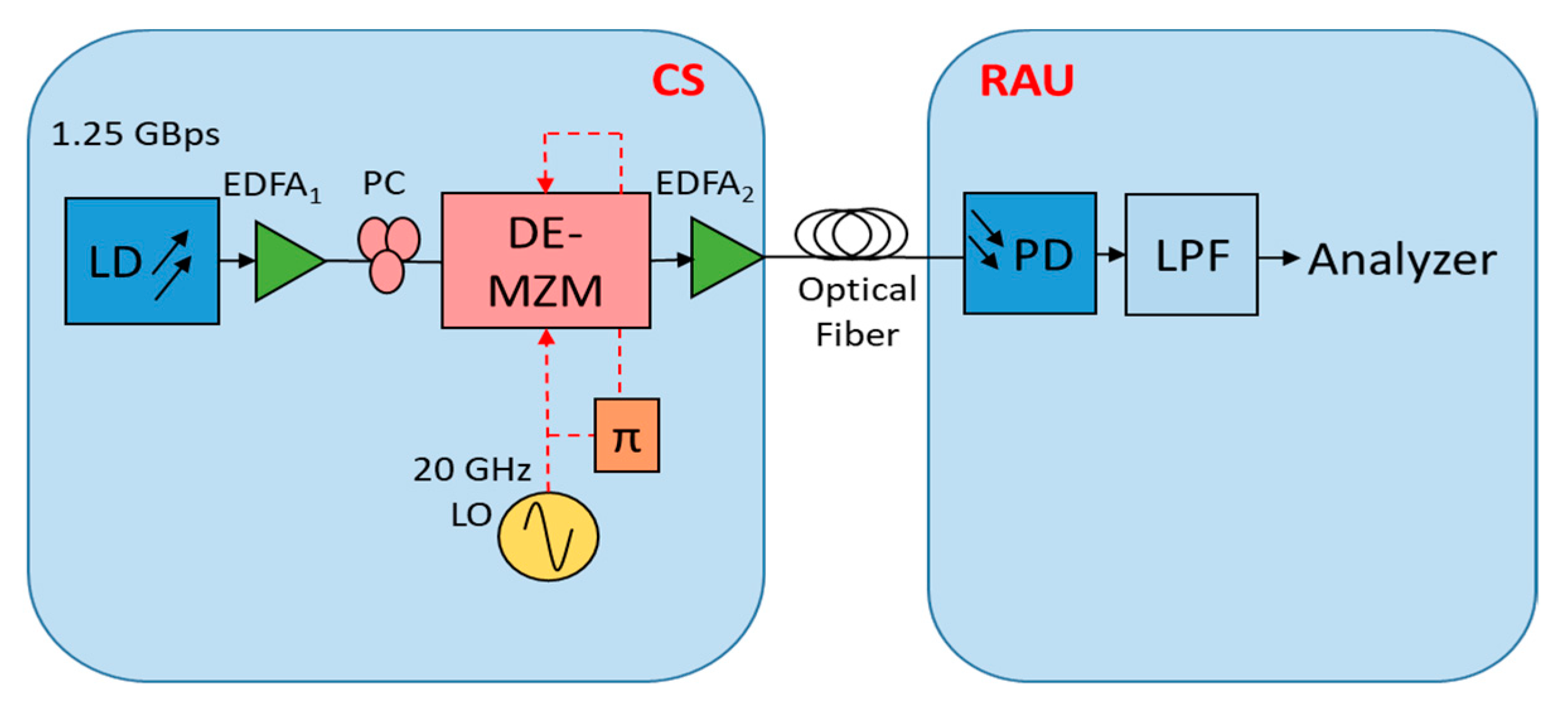
An MZM schematic diagram of the DSB-OCS system is illustrated in Figure 1. The DSB-OCS technique is established using a Dual-Electrode Mach-Zehnder Modulator (DE-MZM) by receiving the optical signal with a wavelength of Ω from the continuous wave (CW) laser diode (LD). Then, the optical signal is divided into two arms, the upper and lower DE-MZM electrodes. The arms contain lithium niobate (Nio3) materials, which cause disturbance to the optical signal to perform the optical modulation. Next, both arms are driven by the RF signal from the local oscillator (LO) with a frequency of ωrf, except that only one of the arms is driven with a 180° phase-shifter. As a result, the system achieves a Dual-Sideband Optical Carrier Suppression as the output, where Ω + ωrf and Ω − ωrf emerge as the sideband from the original signal Ω, as shown in the block diagram in Figure 1 by manipulating the modulator’s DC bias voltage. The DSB-OCS system was theoretically clarified in [27]. A baseband signal of 1.25 Gbps was injected or directly modulated via the CW LD and simulated the system performance via Optisystem software version 17. The simulation was performed using the setup shown in Figure 2 to generate the mm-wave with DSB-OCS technique. A direct modulation laser diode (DMLD) of 1550 nm was used to produce the CW optical signal with an amplitude signal around −10 dBm. The relative intensity noise (RIN) as set at −140 dB/Hz. In order to ensure a full DE-MZM coupling and to minimize the polarization-dependent loss, a polarization controller (PC) was used in the circuit. Then, an erbium-doped fiber amplifier 1 (EDFA1) was utilized to amplify the signal and to overdrive it before sending to a 20 GHz RF signal. A 3 dB splitter divided the RF signal into two equal parts with a 180° phase-shifter in one of the electrodes. Then, both parts drove the upper and lower DE-MZM electrodes. The power of RF signal was 20 dBm at frequency of 20 GHz. The half-wave voltage of the main Vπ was deemed to be 5 V, VDC1 was biased at 5 V, while VDC2 is biased at 0 V.
The DE-MZM output was amplified by EDFA2. After that, the signal was linked to an optical fiber of 0.21 dB/km loss, and 16 ps/(nm.km) chromatic dispersion. At RAU, the photodetector (PD) with 0.6 A/W was used to detect the signals which were then filtered by a lowpass filter (LPF) with cutoff frequency of 0.75x BitRate. Finally, the output signal was connected to an analyzer to collect the data and to perform analysis of the signal.

3. Modulation Index

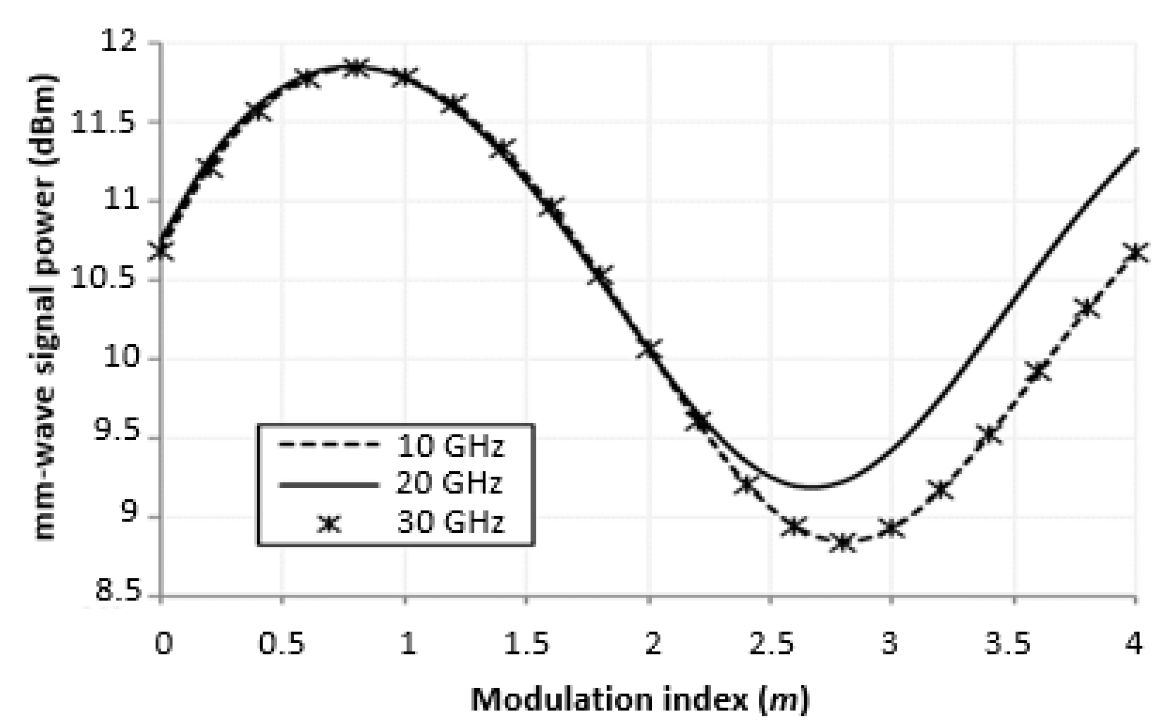
The DSB-OCS system has been modelled to investigate the RoF system performance and the signal power of the mm-wave at various modulation indexes (m). At the DSB-OCS simulation setup, the parameters were kept at constant values and the fiber length was set to 20 km. The important findings were collected and are plotted in Figure 3 and Figure 4. The result in Figure 3 shows the relationship between the mm-wave signal power and the modulation index. In this figure, the amplitude of the LO signals ranges from 0 V to 20 V, and the modulation index ranges from 0 to 4. It can be seen that all curves perform the same behavior in the graph with small differences of around 0.6%, starting at a modulation index of 2.6. However, the 10 GHz and 20 GHz curves have the same output for the whole iteration.
Initially, 10.7 dBm signal power of the mm-wave was generated at a modulation index of 0. When the modulation index as raised, the curves increased gradually to reach the maximum value at 11.8 dBm for modulation indexes from 0.8 to 1. This case can be clarified by Equation (1):
E o u t = E o cos ( Ω t )   n = 0   ( 1 ) n   J 2 n + 1 ( π m 2 ) ·   cos [ ( 2 n + 1 ) ω R F t ]  
where J 2 π + 1  m/2) refers to Bessel functions of the first kind of n order where n = 0 ,   1 ,   2 ,   3 and the related functions J 1   ,   J 3 and J 5 can be represented by Equation (2):
J n   ( x ) = k = 0 ( 1 ) k   ( x 2 ) n + 2 k k !   Γ   ( n + k + 1 )
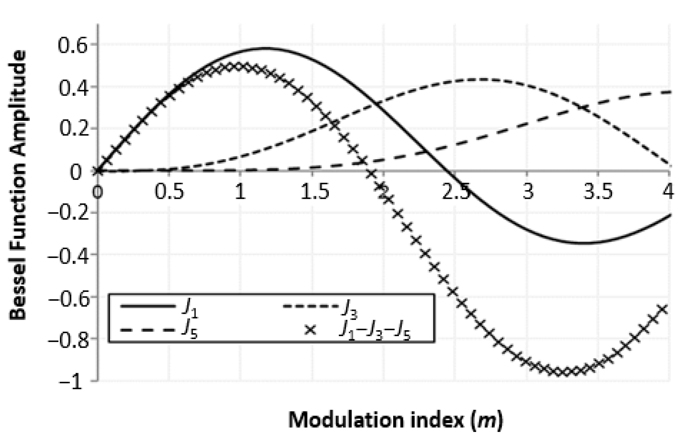
where x = πm/2, m is the modulation index, or VDC/Vπ of the DSB-OCS, VDC is the DC bias voltage, n and k are integers, and ω R F is the optical carrier frequency. Figure 4 displays the theoretical Bessel function with J 1   ,   J 3 and J 5 for comparison. Due to low bias applied, only odd Bessel components are considered. Theoretically, the J 1 portion is dominant compared to J 3 and J 5 at modulation indexes of 0.6 and 1.1, while J 0   and other components are suppressed in the DSB-OCS system. J1 is considered as the dual sideband components, while the dual sideband components for J3 and J5 can be regarded as noise. Theoretically, the term J1J3J5 is the output result of the system. It can be seen that the theoretical J1J3 − J5 term, or the output result of the system, shows maximum mm-wave signal power at a modulation index of 0.6 to 1.1 in Figure 4, and this result coincides with the simulation result in Figure 3.
In Figure 3, the curve of 20 GHz LO records the minimum amplitude values when modulation indexes range from 2.4 to 2.8, while the curves for 10 GHz and 30 GHz record the minimum amplitude values at a modulation index ranging from 2.6 to 3. The 20 GHz curve had higher amplitude after a modulation index of 3 than the curves of 10 GHz and 30 GHz. All curves increased gradually after a modulation index of 3, with a difference of 0.65 dB in the amplitude between the 20 GHz curve and 10 GHz curve. This can also be explained by referring to the J1 − J3 − J5 term plot in Figure 4, where the results coincide with results in Figure 3, and it has been shown that in order to obtain the maximum mm-wave signal power amplitude, the modulation index should be between 0.6 and 1.1.

4. Phase Imbalance

In this section, we discuss the phase imbalance parameter that may affect the performance of optical mm-wave. This comes from the influence of phase imbalance on the insertion loss as well as the DE-MZM modulation indexes. To prove that, we assumed that the inputs of upper and lower DE-MZM electrodes were imbalanced. This imbalance comes from the difference in length ∆L between the two branches. This will cause a phase imbalance (ϕ) at the MZM scheme because of different speeds of beams inside the MZM, therefore different outputs at the MZM. The phase imbalance can be represented by [28]:
ϕ = 2 π nL/λ
where n is the refractive index and λ is the light wave wavelength.
The change in ϕ and splitting ratio (γ) of the two electrodes (upper and lower DE-MZM electrodes) may cause declines in the generated optical mm-wave. Considering the limitation or changing of the γ and ϕ in both electrodes, the mm-wave generated can be represented by:
E ( t ) =   α E ο   e i ω c t { γ [ γ 1 exp ( j π V r f cos ω m   t V π a ) + ( 1 γ 1 ) exp ( j π V r f cos ω m   t V π a ) ]   e j φ + ( 1 γ ) × [ γ 2 exp ( j π V r f cos ( ω m   t + π 2 ) V π b )   e j φ + ( 1 γ 2 ) exp ( j π V r f cos ( ω m   t + π 2 )   V π b ) ] } = α   E ο     e j ω c t   { γ [ γ 1   e j m cos ω m t + ( 1 γ 1 ) e j m cos ω m t ]   e j φ + ( 1 γ ) [ γ 2   e j m sin ω m t + ( 1 γ 2 )   e j m sin ω m t   ] } = α   E ο     e j ω c t   { γ [ γ 1   n = j n   J n   ( m ) e j n ω m t + ( 1 γ 1 )   n = ( j n )   J n   ( m ) e j n ω m t ]   e j φ + ( 1 γ ) × [ γ 2   n = ( 1 ) n   J n   ( m ) e j n ω m t + ( 1 γ 2 )   n =   J n   ( m ) e j n ω m t ] } = α   E ο   n = [ γ γ 1 e j φ   j n + γ   ( 1 γ 1 ) e j φ ( j ) n + ( 1 γ ) γ 2   ( 1 ) n + ( 1 γ ) ( 1 γ 2 ]   J n ( m ) e j ( ω c + n ω m ) t = α   E ο     n = A n J n ( m ) e j ( ω c + n ω m ) t
where E ο is the light wave amplitude and α is the modulator insertion loss, ω c is an angular frequency, Vrf is the voltage of local oscillator, m is the modulation index, V π a and V π a are the switching voltages of the two upper and lower DE-MZM electrodes, and Va and Vb are the two bias voltages where Va = Vb.
The An can be expressed as:
A n = { γ   e j φ + ( 1 γ ) , n = 4 m j γ ( 1 2 γ 1 ) e j φ + ( 1 γ ) ( 1 2 γ 2 ) , n = 4 m + 1 j γ e j φ + ( 1 γ ) , n = 4 m + 2 j γ ( 1 2 γ 1 ) e j φ + ( 1 γ ) ( 1 2 γ 2 ) , n = 4 m + 3
Assuming that the two electrodes of DE-MZM have a γ of γ1 and γ2, in the case of γ1 = γ2 = 0.5 and ϕ = 0, Equation (4) becomes Equation (6) [28]. The orders of n = 4 m + 1 ,   n = 4 m + 2   and   n = 4 m + 3 can be ignored.
E ( t ) = α   E ο   e j ω c t n = J 4 n ( m ) e j ( ω c + 4 n ω m ) t α   E ο   { J o ( m ) e j ω c t + J 4 ( m ) [ e j ( ω c + 4 ω m ) t + e j ( ω c 4 ω m ) t ] + J 8 ( m ) [ e j ( ω c + 8 ω m ) t + e j ( ω c 8 ω m ) t ] + } .
However, the declination of the original values causes some limitations in the 4m order sidebands and further (4m + 1st), (4m + 2nd), and (4m + 3rd) order sidebands. We can see from these equations that the amplitude mostly depends on the γ and the ϕ. For instance, the amplitude of the 4m can be expressed by:
| A 4 m | = 1 + 2   γ 2 2 γ + 2 γ ( 1 γ ) cos φ
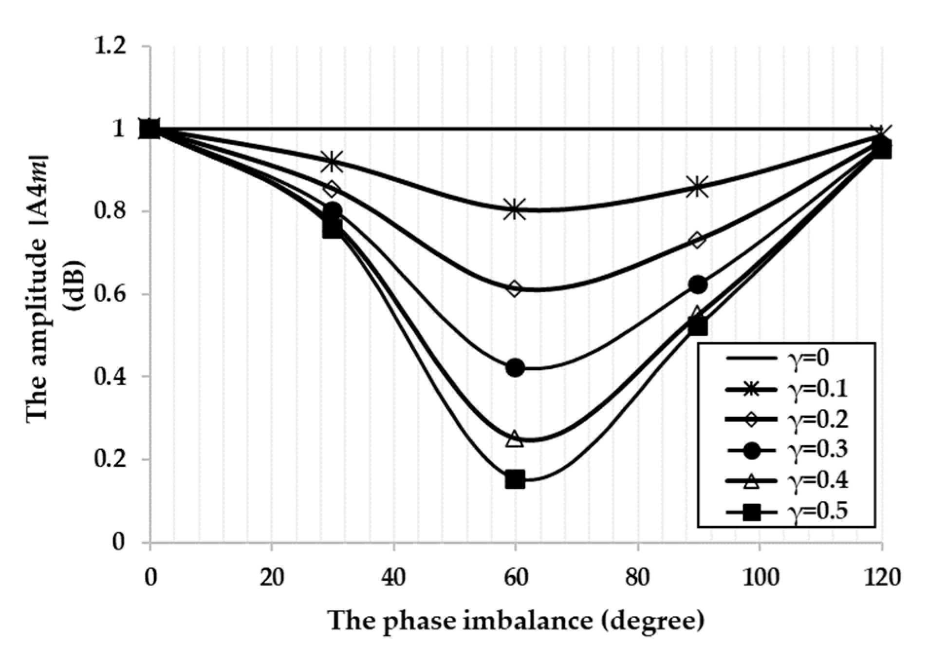
Figure 5 indicates the relationship between the ϕ and the amplitude when optical γ is varied from 0 to 0.5. The increase in the ϕ from 0 to 90° causes decrease in the 4m order sideband. It can be seen that when γ is equal to zero, the greatest value of amplitude will be formed. This suggests that the influence of ϕ is greater than γ.
According to the theoretical analysis on both γ and ϕ, we can confirm that both of them affect the amplitude of the generated optical mm-wave. It is worth noting that the influence of phase imbalance is greater than the splitting ratio. It is important to take this point into consideration when generating an optical mm-wave in addition to adjusting the DC bias voltage and the LO voltages. It is obvious that the mm-wave signal power and the phase imbalance are dependent on the insertion losses and the modulation indexes of the DE-MZM.

5. Effect of Optical Fiber Dispersion

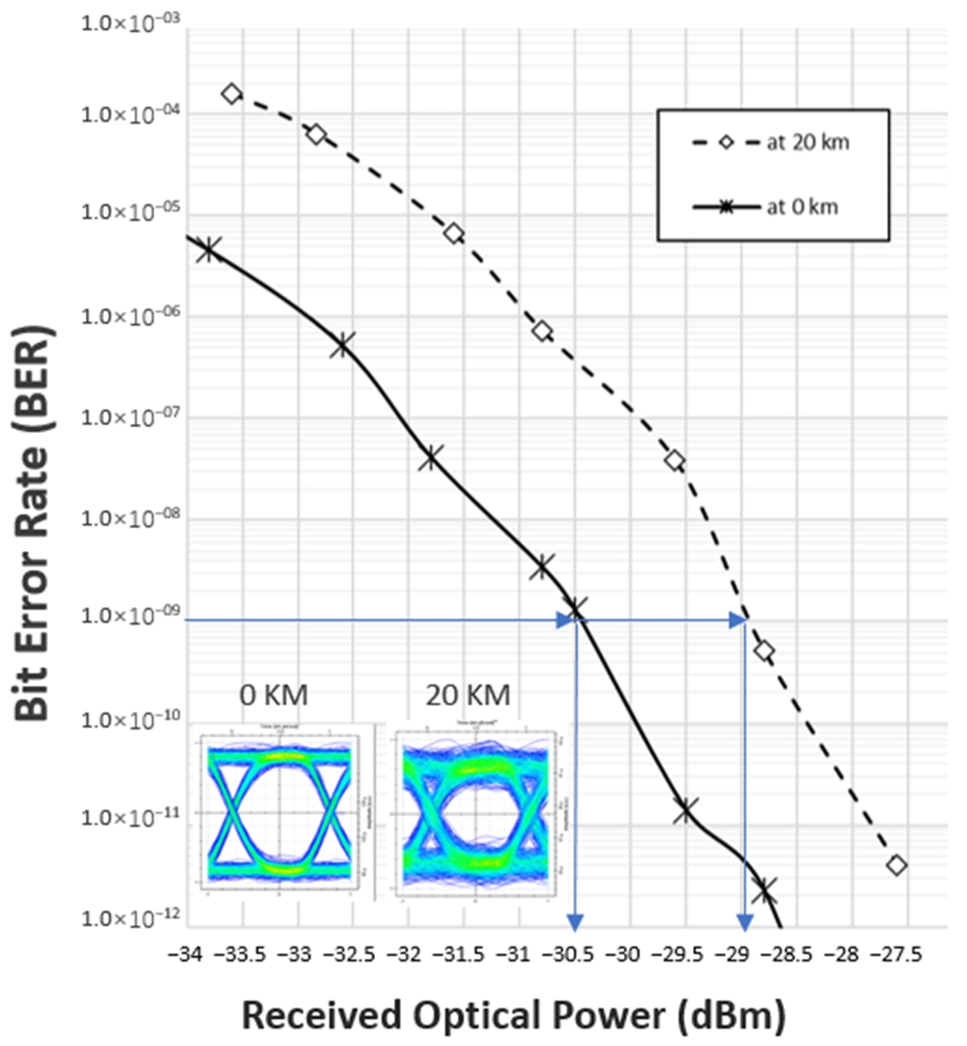
In this section, the effect of dispersion is studied to investigate the performance of the RoF system and the signal power of the mm-wave at different optical fiber lengths. The simulation results of the proposed architecture showed acceptable performance of the RoF system: the system obtained a BER of 2.6 × 10⁻¹⁰ and Q factor of 6.2 for the 1.25 Gbps signal. Figure 6 shows the relationship between BER and the received optical power (ROP) at 0 km and 20 km fiber length. From the graph, it can be seen that the power penalty is 1.5 dBm between the 0 km and 20 km lines at a BER of 10−9, where the system achieves error-free transmission.
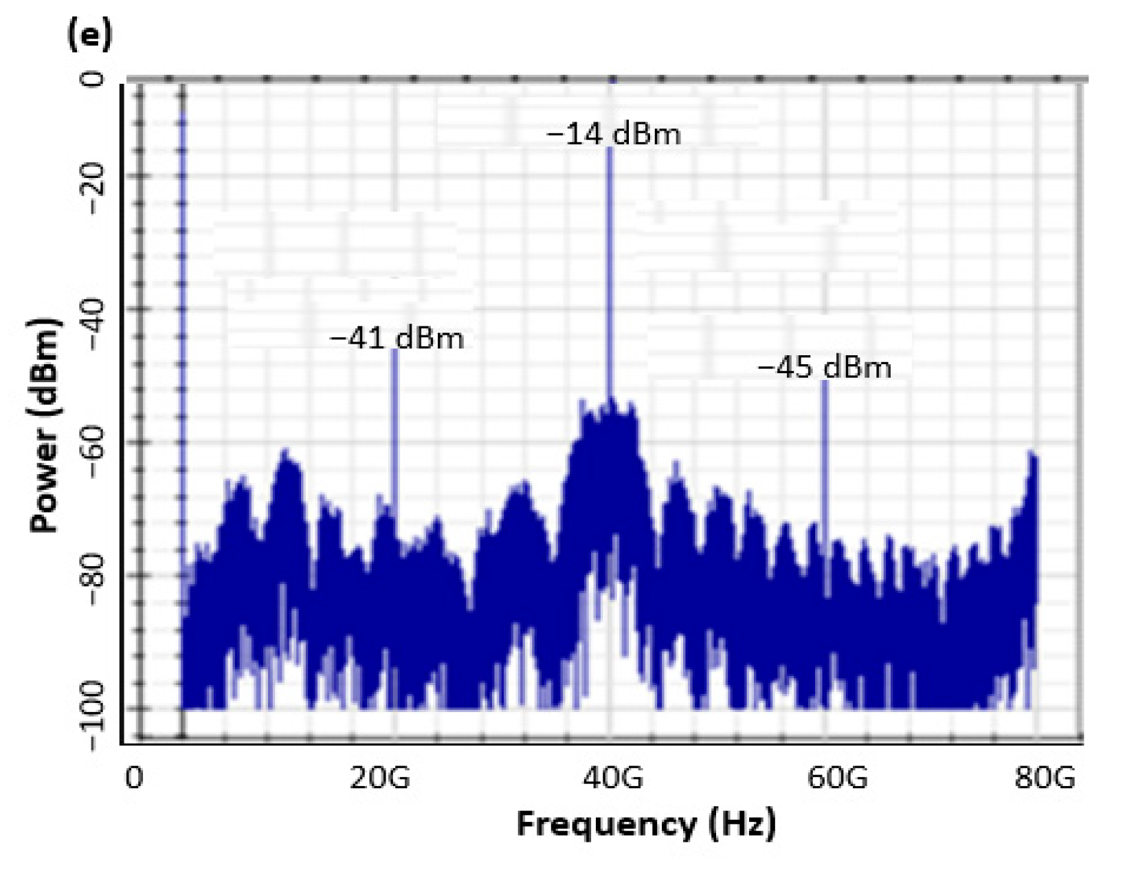
To show the dispersion effects, the optical fiber length was varied from 0 km to 40 km and dispersion was considered at 16 ps/(nm/km). The parameters for CW laser, PD, EDFA1 and EDFA2 were kept at the same settings. The results in Figure 7a–e show the effects of dispersion on the DSB-OCS system and how it contributes to changing the output spectrum of 40 GHz.
Figure 7a shows the 40 GHz output spectrum with a 0 dBm peak and 80 dB SNR at 0 km fiber length. Figure 7b shows that the SNR decreases to 54 dB, while the peak of 40 GHz remains at 0 dBm at 10 km fiber length. At this length, the components of 20 GHz and 60 GHz appear with amplitudes of −27 dBm and −38 dBm, respectively. Figure 7c shows that the peak of 40 GHz output spectrum is −5 dBm and the SNR value drops to 44 dB at 20 km fiber length. The component amplitudes of 20 GHz and 60 GHz are −45 dBm and −36 dBm, respectively. Figure 7d shows that the peak of the 40 GHz output spectrum is −10 dBm and the value of the SNR is 42 dB at 30 km fiber length, while the component amplitudes of 20 GHz and 60 GHz are −43 dBm and −38 dBm, respectively. Finally, Figure 7e shows that the peak of the 40 GHz output spectrum is −14 dBm and the SNR is 42 dB at 40 km fiber length, whereas the component amplitudes of 20 GHz and 60 GHz are −41 dBm and −45 dBm, respectively. It is obvious that the 40 GHz amplitude and the SNR is decreasing with the increase in optical fiber length. The amplitude of 40 GHz is reduced to −14 dB after increasing the fiber length to 40 km. Additionally, the amplitude of SNR drops to 44 dB after 40 km fiber length. Therefore, the effect of optical fiber dispersion occurs with the increase in optical fiber length. To investigate more into dispersion parameter, we can refer to the formula [29]:
D = 2 π C λ 2   β 2  
where D is the dispersion [ps/(nm/km)], C represents the light speed in (ps), λ represents the wavelength in (nm), and β2 represents the second-order propagation constant. The D value degrades the RoF system due to the high utilization of optical bandwidth, as displayed in Figure 7. The degradation of system influences more on the DSB system than the OCS. This because the speed of the sideband is different from the speed at which the carrier propagates in the fiber. Later, both arrive with an introduced delay and inter-mix with the optical signal at the detector. Therefore, the system would experience power loss and signal broadening, which makes it difficult to decode the received data. Another study provides a comprehensive description of dispersion and its influence on the DSB-OCS output [30].
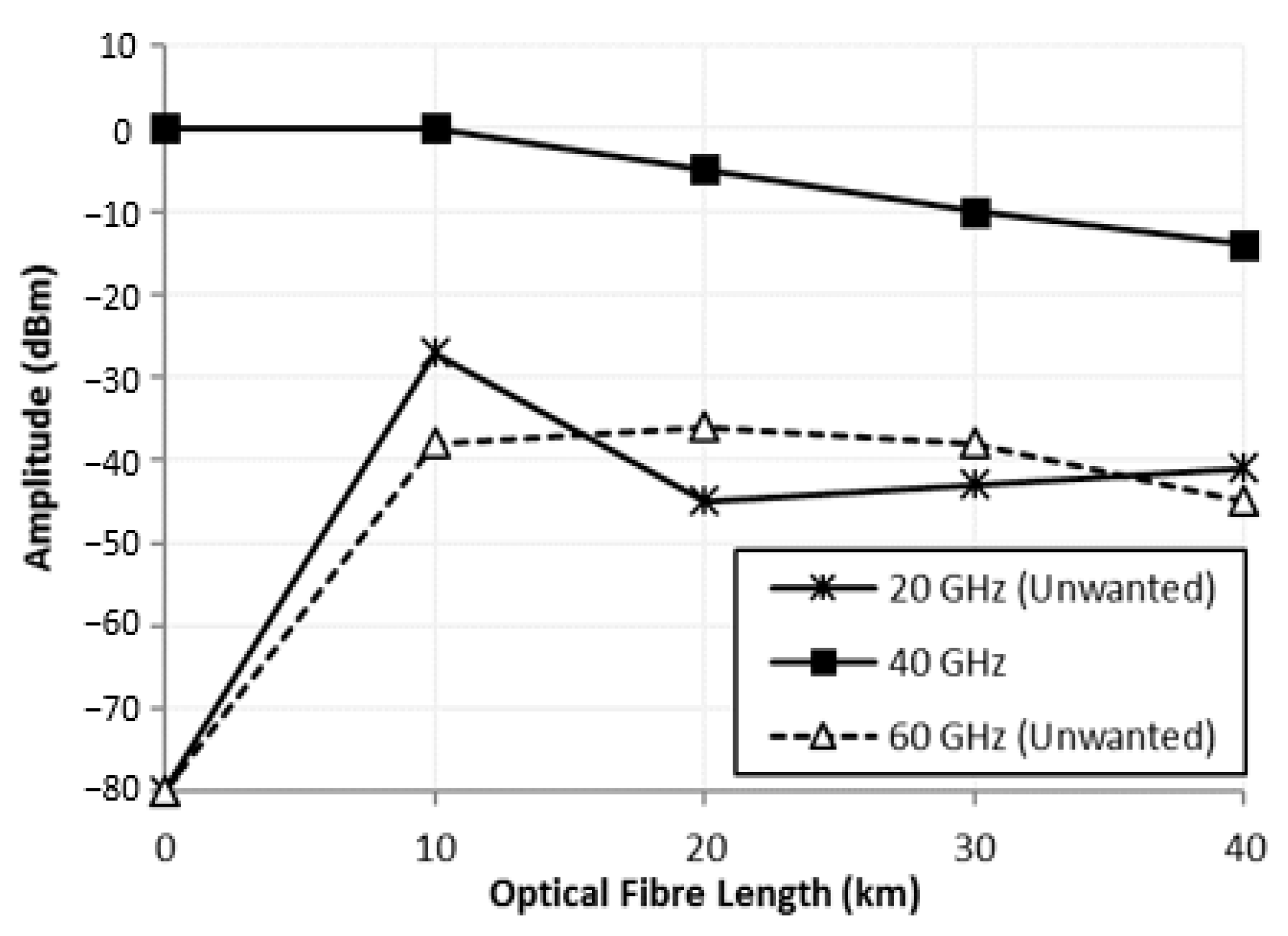
Figure 8 illustrates the relationship between the mm-wave signal amplitude in dBm and different optical fiber distance. In this graph, the optical fiber length varies from 0 to 40 km distance, while the amplitudes for the mm-wave signals range from 0 dBm to −80 dBm. It can be observed that the graph of 40 GHz is different from 20 GHz and 60 GHz; the 40 GHz graph is more linear than the others with big difference in amplitude power. In the graph, the 40 GHz level is above the other signals, 20 GHz and 60 GHz, with a power difference of 28 dBm at 10 km distance. Based on this graph, we can conclude that the DSB-OCS system is compatible more with a 40 GHz mm-wave signal than the others. The linearity for such a system can be enhanced using various techniques, for instance, ref. [31] used the direct digital predistortion technique to improve the laser chirp and fiber dispersion in long-haul RoF links. However, the process of converting the signal from the digital form to analog form was found to induce distortion in the signal [32]. Additionally, it is possible to avoid a dispersion penalty using single-sideband (SSB) modulation and DSB in the system [33], or using a tunable dispersion-compensation module [34].

6. Conclusions

We studied the modulation index, phase imbalance, and dispersion to observe the effects of these parameters on the performance of an RoF system through the DSB-OCS technique. The system successfully generated an optical mm-wave by using DE-MZM. Several LO frequencies have been applied to generate a wireless carrier for the data transmission through the RoF systems at different fiber lengths. The performance of the system has been tested with various modulation indexes where the maximum mm-wave signal power amplitude can be achieved with a modulation index between 0.6 and 1.1. The phase imbalance and insertion loss have been theoretically analyzed. The performance evaluations of the system show that the output mm-wave signal power increased when the modulation index of the MZM was increased. The study also shows that phase imbalance and optical splitting ratio affect the power of the generated optical mm-wave. Thus, the generated mm-wave signal power and the phase imbalance are dependent on the insertion losses and the modulation indexes of the DE-MZM. It was also found that dispersion of the optical fiber influences the performance of the system through reducing the mm-wave amplitude and SNR with the increase in fiber length. The system presented has great potential in future optical and wireless access networks.

Author Contributions

S.Y. and R.M.M. studied and simulated all the data; Z.Z. consulted on the modulation index section, and review and editing; A.M., C.B.M.R. and S.B.A.A. consulted on the dispersion section and reviewed the paper. All authors have read and agreed to the published version of the manuscript.

Funding

This work supported by the Fundamental Research Grant (FRGS), Ministry of Higher Education, Malaysia, No. FRGS/1/2019/TK04/UPM/02/07 and Inisiatif Putra Muda Grant by Universiti Putra Malaysia, No. GP-IPM/2017/9524100.

Conflicts of Interest

The authors declare no conflict of interest.

References

  1. Sanchez, M.G. Millimeter-Wave (mmWave) Communications; MDPI: Basel, Switzerland, 2020. [Google Scholar]
  2. Chauhan, S.; Miglani, R.; Kansal, L.; Gaba, G.S.; Masud, M. Performance analysis and enhancement of free space optical links for developing state-of-the-art smart city framework, photonics. Photonics 2020, 7, 132. [Google Scholar] [CrossRef]
  3. Wibisono, G.; Ujang, F.; Firmansyah, T.; Priambodo, P.S. Asymmetric carrier divider with an irregular RF phase on DD-MZ modulator for eliminating dispersion power fading in RoF communication. Photonics 2020, 7, 106. [Google Scholar] [CrossRef]
  4. Giannoulis, G.; Argyris, N.; Iliadis, N.; Poulopoulos, G.; Kanta, K.; Apostolopoulos, D.; Avramopoulos, H. Analog radio-over-fiber solutions for 5G communications in the beyond-CPRI era. In Proceedings of the 20th International Conference on Transparent Optical Networks (ICTON), Bucharest, Romania, 1–5 July 2018; IEEE: Piscataway, NJ, USA, 2018; pp. 1–5. [Google Scholar]
  5. Hadi, M.U.; Awais, M.; Raza, M. Multiband 5G NR-over-fiber system using analog front haul. In Proceedings of the International Topical Meeting on Microwave Photonics (MWP), Matsue, Japan, 24–26 November 2020; IEEE: Piscataway, NJ, USA, 2020; pp. 136–139. [Google Scholar]
  6. Mitsolidou, C.; Vagionas, C.; Mesodiakaki, A.; Maniotis, P.; Kalfas, G.; Roeloffzen, C.G.H.; van Dijk, P.W.L.; Oldenbeuving, R.M.; Miliou, A.; Pleros, N. A 5G C-RAN optical fronthaul architecture for hotspot areas using OFDM-based analog IFoF waveforms. Appl. Sci. 2019, 9, 4059. [Google Scholar] [CrossRef] [Green Version]
  7. Hadi, M.U.; Ghaffar, S.; Murtaza, G. 5G NR MIMO enabled multiband fiber wireless system using analog optical front haul. In Proceedings of the 17th International Conference on Smart Communities: Improving Quality of Life Using ICT, IoT and AI (HONET), Charlotte, CA, USA, 14–16 December 2020; IEEE: Piscataway, NJ, USA, 2020; pp. 59–62. [Google Scholar]
  8. Lu, M.; Hyun-Chul, P.; Parker, J.S.; Bloch, E.; Sivananthan, A.; Griffith, Z.; Johansson, L.A.; Rodwell, M.J.; Coldren, L.A. A heterodyne optical phase-locked loop for multiple applications. In Proceedings of the Optical Fiber Communication Conference and Exposition and the National Fiber Optic Engineers Conference (OFC/NFOEC), Anaheim, CA, USA, 17–21 March 2013; IEEE: Piscataway, NJ, USA, 2013; pp. 1–3. [Google Scholar]
  9. Prabakaran, M.B.R. Photonic generation of microwave pulses using stimulated Brillouin scattering (SBS)-based carrier processing and data transmission for radio over fiber (RoF) systems. In Proceedings of the International Conference on Wireless Communications, Signal Processing and Networking (WiSPNET), Chennai, India, 23–25 March 2016; pp. 372–375. [Google Scholar]
  10. Mohamad, R.; Zamzuri, A.K.; Yaakob, S.; Idrus, S.M.; Supaat, A.S. Internally generated 21.6-GHz millimeter wave based on brillouin fiber laser. In Proceedings of the International Conference on Electrical Engineering and Informatics, Bandung, Indonesia, 17–19 July 2011; IEEE: Piscataway, NJ, USA, 2011; pp. 1–3. [Google Scholar]
  11. Tian, Y.; Lee, K.-L.; Lim, C.; Nirmalathas, A. Experimental comparison of DSB-SC & OSSB based 60 GHz radio-over-fiber fronthaul links. In Proceedings of the IEEE International Topical Meeting on Microwave Photonics (MWP), Long Beach, CA, USA, 31 October–3 November 2016; IEEE: Piscataway, NJ, USA, 2016; pp. 141–144. [Google Scholar]
  12. Prakash, S.; Bhatia, R.; Saini, E. Performance evaluation of ROF communication link using DSB and SSB modulated signals compensated with parallel modulation scheme. In Proceedings of the International Conference on Computing, Communication and Automation (ICCCA), Greater Noida, India, 29–30 April 2016; IEEE: Piscataway, NJ, USA, 2016; pp. 1550–1553. [Google Scholar]
  13. Ujang, F.; Firmansyah, T.; Priambodo, P.S.; Wibisono, G. Irregular shifting of RF driving signal phase to overcome dispersion power fading. Photonics 2019, 6, 104. [Google Scholar] [CrossRef] [Green Version]
  14. Nor, M.; Kanesan, T.; Maskurju, F.; Yusof, A.; Fatah, F.A.; Anas, S. Experimental realization of multi-service RoF system using OCS-PolMux techniques. In Proceedings of the 19th International Conference on Advanced Communication Technology (ICACT), PyeongChang, Korea, 19–22 February 2017; IEEE: Piscataway, NJ, USA, 2017; pp. 148–151. [Google Scholar]
  15. Li, X.; Xiao, J.; Wang, Y.; Xu, Y.; Chen, L.; Yu, J. W-band QPSK vector signal generation based on photonic heterodyne beating and optical carrier suppression. In Proceedings of the Optical Fiber Communications Conference and Exhibition (OFC), Anaheim, CA, USA, 20–22 March 2016; IEEE: Piscataway, NJ, USA, 2016; pp. 1–3. [Google Scholar]
  16. Hilt, A. Microwave harmonic generation in fiber-optical links. In Proceedings of the 13th International Conference on Microwaves, Radar and Wireless Communications. MIKON-2000. Conference Proceedings (IEEE Cat. No. 00EX428), Wroclaw, Poland, 22–24 May 2000; IEEE: Piscataway, NJ, USA, 2000; pp. 693–698. [Google Scholar]
  17. Hsueh, Y.-T. Frontiers of Optical Networking Technologies: Millimeter-Wave Radio-Over-Fiber and 100G Transport System for Next-Generation High-Data-Rate Applications; Georgia Institute of Technology: Atlanta, GA, USA, 2012. [Google Scholar]
  18. Thomas, V.A.; Ghafoor, S.; El-Hajjar, M.; Hanzo, L. A full-duplex diversity-assisted hybrid analogue/digitized radio over fibre for optical/wireless integration. IEEE Commun. Lett. 2013, 17, 409–412. [Google Scholar] [CrossRef] [Green Version]
  19. Chang, Q.; Tian, Y.; Gao, J.; Ye, T.; Li, Q.; Su, Y. Generation and transmission of optical carrier suppressed-optical differential (quadrature) phase-shift keying (OCS-OD (Q) PSK) signals in radio over fiber systems. J. Lightwave Technol. 2008, 26, 2611–2618. [Google Scholar] [CrossRef]
  20. Lim, C.; Yang, Y.; Nirmalathas, A. High performance fiber-radio link: Digitized radio-over-fiber. In Proceedings of the Asia Communications and Photonics Conference (ACP), Guangzhou, China, 7–10 November 2012; IEEE: Piscataway, NJ, USA, 2012; pp. 1–3. [Google Scholar]
  21. Paredes-Páliz, D.F.; Royo, G.; Aznar, F.; Aldea, C.; Celma, S. Radio over fiber: An alternative broadband network technology for IoT. Electronics 2020, 9, 1785. [Google Scholar] [CrossRef]
  22. Breyne, L.; Torfs, G.; Yin, X.; Demeester, P.; Bauwelinck, J. Comparison between analog radio-over-fiber and sigma delta modulated radio-over-fiber. IEEE Photonics Technol. Lett. 2017, 29, 1808–1811. [Google Scholar] [CrossRef] [Green Version]
  23. Hadi, M.U.; Jung, H.; Ghaffar, S.; Traverso, P.A.; Tartarini, G. Optimized digital radio over fiber system for medium range communication. Optics Commun. 2019, 443, 177–185. [Google Scholar] [CrossRef]
  24. Zakrzewski, Z. D-RoF and A-RoF interfaces in an all-optical fronthaul of 5G mobile systems. Appl. Sci. 2020, 10, 1212. [Google Scholar] [CrossRef] [Green Version]
  25. Souza, R.H.D.; Coutinho, O.L.; Oliveira, J.E.B.; Ferreira Júnior, A.A.; Ribeiro, J.A.J. An analytical solution for fiber optic links with photonic-assisted millimeter wave upconversion due to MZM nonlinearities. J. Microw. Optoelectron. Electromagn. Appl. 2017, 16, 237–258. [Google Scholar] [CrossRef] [Green Version]
  26. Mekonnen, K.A.; van Zantvoort, J.H.C.; Tessema, N.M.; Cao, Z.; Tangdiongga, E. Integrated optical reflective amplified modulator for indoor millimetre wave radio-over-fibre applications. Electron. Lett. 2017, 53, 285–287. [Google Scholar] [CrossRef] [Green Version]
  27. Yaakob, S.; Kadir, M.Z.A.; Idrus, S.M.; Samsuri, N.M.; Mohamad, R.; Farid, N.E. On the carrier generation and HD signal transmission using the millimeter-wave radio over fiber system. Optik 2013, 124, 6172–6177. [Google Scholar] [CrossRef]
  28. Ma, J.; Xin, X.; Yu, J.; Yu, C.; Wang, K.; Huang, H.; Rao, L. Optical millimeter wave generated by octupling the frequency of the local oscillator. J. Opt. Netw. 2008, 7, 837–845. [Google Scholar] [CrossRef]
  29. Agrawal, G.P. Lightwave Technology: Telecommunication Systems; John Wiley & Sons: Hoboken, NJ, USA, 2005. [Google Scholar]
  30. Ma, J.; Yu, J.; Yu, C.; Xin, X.; Zeng, J.; Chen, L. Fiber dispersion influence on transmission of the optical millimeter-waves generated using LN-MZM intensity modulation. J. Lightwave Technol. 2007, 25, 3244–3256. [Google Scholar] [CrossRef]
  31. Hadi, M.U.; Nanni, J.; Polleux, J.-L.; Traverso, P.A.; Tartarini, G. Direct digital predistortion technique for the compensation of laser chirp and fiber dispersion in long haul radio over fiber links. Opt. Quantum Electron. 2019, 51, 1–20. [Google Scholar] [CrossRef]
  32. Meslener, G. Chromatic dispersion induced distortion of modulated monochromatic light employing direct detection. IEEE J. Quantum Electron. 1984, 20, 1208–1216. [Google Scholar] [CrossRef]
  33. Won, P.; Zhang, W.; Williams, J. Self-phase modulation dependent dispersion mitigation in high power SSB and DSB + dispersion compensated modulated radio-over-fiber links. In Proceedings of the MTT-S International Microwave Symposium Digest, San Francisco, CA, USA, 11–16 June 2016; IEEE: Piscataway, NJ, USA, 2006; pp. 1947–1950. [Google Scholar]
  34. Ilgaz, M.A.; Baliž, K.V.; Batagelj, B. A flexible approach to combating chromatic dispersion in a centralized 5G network. Opto Electron. Rev. 2020, 28, 35–42. [Google Scholar]
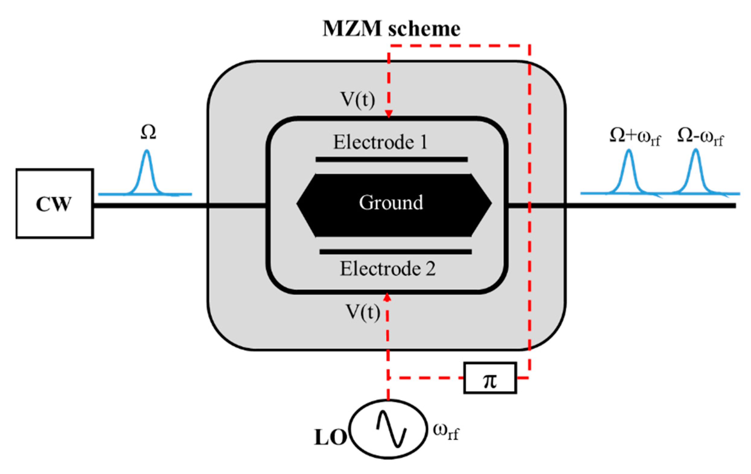
Figure 1. DSB-OCS schematic diagram.
Photonics 08 00153 g001
Figure 2. DSB-OCS simulation setup.
Photonics 08 00153 g002
Figure 3. Signal power of optical mm-wave as a function of modulation index (m) for different LO frequencies.
Photonics 08 00153 g003
Figure 4. Bessel functions of the first kind.
Photonics 08 00153 g004
Figure 5. Effect of both optical splitting ratio γ and the phase imbalance ϕ on the 4m order sideband.
Photonics 08 00153 g005
Figure 6. BER vs. the received optical power (ROP) at 0 km and 20 km fiber length.
Photonics 08 00153 g006
Figure 7. DSB-OCS electrical output spectra at different optical fiber lengths. (a) 0 km; (b) 10 km; (c) 20 km; (d) 30 km; (e) 40 km.
Photonics 08 00153 g007aPhotonics 08 00153 g007b
Figure 8. mm-wave amplitudes vs. fiber lengths.
Photonics 08 00153 g008
Publisher’s Note: MDPI stays neutral with regard to jurisdictional claims in published maps and institutional affiliations.