Article

2.58 kW Narrow Linewidth Fiber Laser Based on a Compact Structure with a Chirped and Tilted Fiber Bragg Grating for Raman Suppression

1
College of Advanced Interdisciplinary Studies, National University of Defense Technology, Changsha 410073, China
2
Hunan Provincial Key Laboratory of High Energy Laser Technology, Changsha 410073, China
3
State Key Laboratory of Pulsed Power Laser Technology, Changsha 410073, China
*
Author to whom correspondence should be addressed.
Photonics 2021, 8(12), 532; https://doi.org/10.3390/photonics8120532
Submission received: 3 October 2021 / Revised: 20 November 2021 / Accepted: 22 November 2021 / Published: 25 November 2021
(This article belongs to the Special Issue High-Power Lasers and Amplifiers)

Abstract

:
We report a high power, narrow linewidth fiber laser based on oscillator one-stage power amplification configuration. A fiber oscillator with a center wavelength of 1080 nm is used as the seed, which is based on a high reflection fiber Bragg grating (FBG) and an output coupling FBG of narrow reflection bandwidth. The amplifier stage adopted counter pumping. By optimizing the seed and amplifier properties, an output laser power of 2276 W was obtained with a slope efficiency of 80.3%, a 3 dB linewidth of 0.54 nm and a signal to Raman ratio of 32 dB, however, the transverse mode instability (TMI) began to occur. For further increasing the laser power, a high-power chirped and tilted FBG (CTFBG) was inserted between the backward combiner and the output passive fiber, experimental results showed that both the threshold of Stimulated Raman scattering (SRS) and TMI increased. The maximum laser power was improved to 2576 W with a signal to Raman ratio of 42 dB, a slope efficiency of 77.1%, and a 3 dB linewidth of 0.87 nm. No TMI was observed and the beam quality factor M2 maintained about 1.6. This work could provide a useful reference for obtaining narrow-linewidth high-power fiber lasers with high signal to Raman ratio.

1. Introduction

In the past years, owing to the great improvement of laser diodes (LDs) brightness and high-quality large mode area (LMA) fiber as well as beam combining technology, the output power of continuous-wave (CW) fiber lasers has been scaled rapidly [1,2,3,4]. However, the further improvement of single fiber output power is limited by various nonlinear effects, transverse mode instability (TMI), thermal effect, etc. For the present single fiber lasers, further power scaling is even difficult with compromise in bandwidth, beam quality, and so on. Spectral beam combining (SBC) is a promising approach to break through the limitations of the fiber lasers [5,6]. In SBC, the key is that the sub beam needs to be a narrow linewidth fiber laser (NLFL) with high beam quality, which usually realize by a main oscillator power amplifier (MOPA) configuration [7]. At present, there is no unified definition about the “narrow” of NLFLs. Considering its practical application in SBC, in this paper, the linewidth of NLFLs is defined as <1 nm. For MOPA structure, there are two main types of seeds, namely few longitudinal mode fiber oscillator laser (FOL) seed and phase modulated single-frequency laser (PMSFL) seed. The method utilizing a phase modulation seed for power amplification is relatively mature, benefiting from the stable temporal property, high nonlinear effects threshold and spectral purity during the amplification process [8,9,10]. Up to now, the power of NLFL based on the PMSFL seed has been scaled to several thousand watts [10,11,12,13,14,15,16,17], and the highest power of NLFL has exceeded 5 kW [16,17]. For MOPA structure based on a FOL seed, because of its simple, compact and economical structure, it has also attracted enormous attention in recent years [18,19,20,21,22,23]. By this method, the maximum power also reached 3 kW [23]. However, among the factors currently limiting the further power scaling of NLFLs based on FOL seed, Stimulated Raman scattering (SRS) is one of the most important limitations. Since the injecting seed laser is not strictly single mode and is usually broadened during the power scaling process in the amplifier. The onset of SRS would bring about a series of problems, such as signal power declination, beam quality deterioration, fiber component damage, etc. [24,25]. Furthermore, the SRS of NLFLs would affect the beam quality of output and the efficient after spectral beam combining. Thus, high power NLFLs with high signal to Raman ratio are becoming increasingly important for SBC.
Many methods have been used to suppress SRS in high-power fiber lasers, including the large-mode-area (LMA) fibers, spectrally selective fibers, long-period fiber gratings, chirped tilted fiber Bragg gratings (CTFBGs), and so on [26,27,28,29,30,31]. Among these methods, CTFBG is considered a comparatively suitable component for SRS suppression. With a tilt angle introduced chirped FBG, CTFBG can couple the forward core mode, which are originally transmitted only in the core, to backward core modes and the cladding modes. Due to its simplicity of application and good spectrum stability, CTFBGs utilized as broadband spectral filters have been extensively studied. In 2017, we firstly proposed and demonstrated using CTFBG to suppress SRS in high-power fiber amplifier [26]. Then, with the improvement of CTFBG fabrication technology, the power handling capability of CTFBGs kept refreshing, which has increased from hundred watts to the kilowatts level [27,28,29,30,31]. These studies are all based on the conventional high-power fiber laser, whose linewidth is in several nanometers level and not belongs to narrow linewidth. So far, there is no report that CTFBG used to suppress SRS in NLFLs, especially in the output of fiber laser handling multi-kW laser power to directly filter SRS.
Here, we report a counter pumped MOPA configuration NLFL based on a FOL seed and CTFBG suppressing SRS. A CTFBG with carrying high power capability is applied to directly filter forward SRS at the output of multi-kW level fiber laser. With the CTFBG included, both the threshold of SRS and TMI increased, and the output power reached to 2.58 kW with a power improvement of 300 W compared that without CTFBG, and the laser slope efficiency was about 77.1%. At the output spectrum of the maximum power, the signal to Raman ratio was 42 dB, and the 3 dB linewidth was about 0.87 nm. The beam quality factor M2 maintained about 1.6 during the power scaling. This work is helpful for obtaining high-power narrow-linewidth fiber lasers with high signal to Raman ratio.

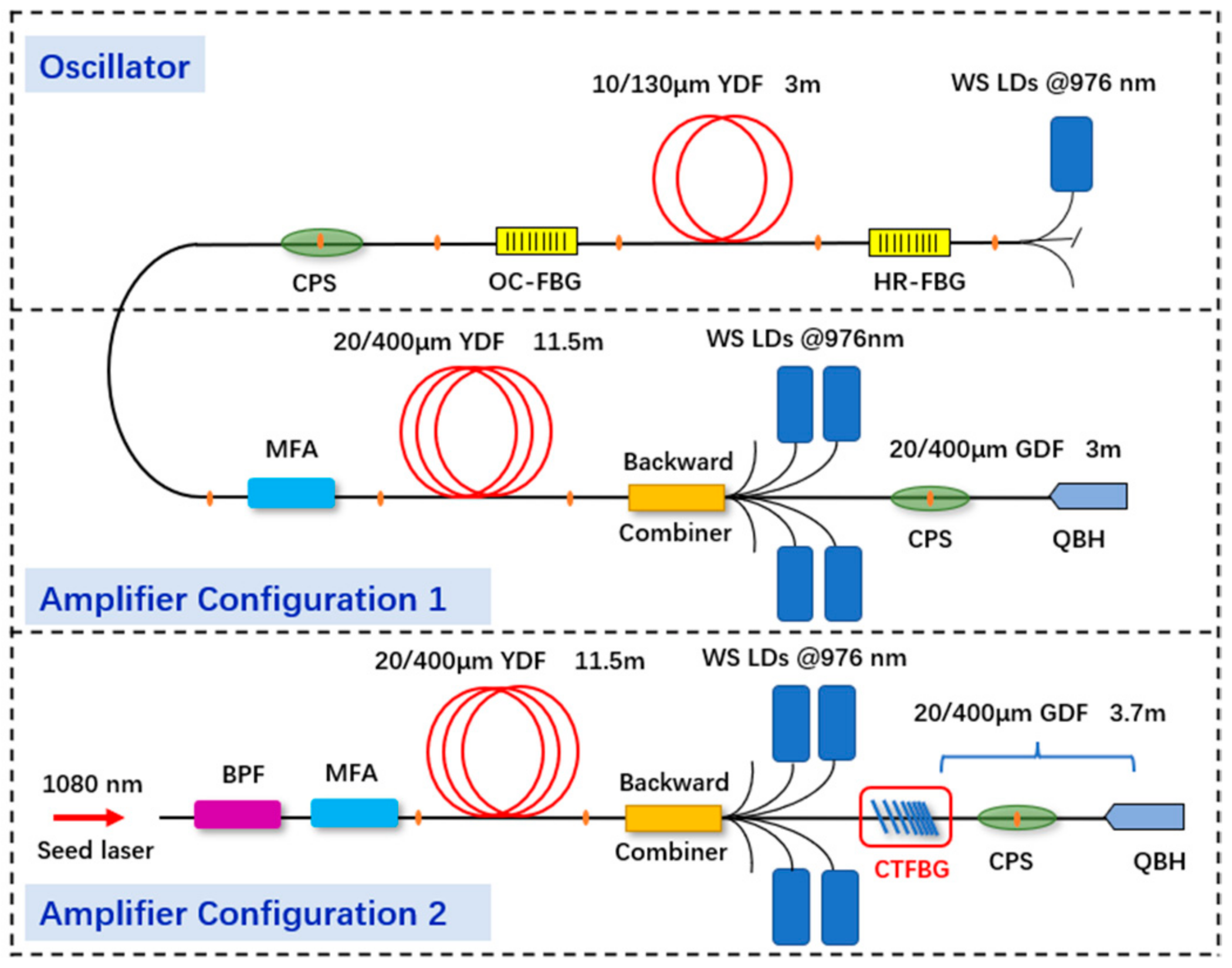
2. Experimental Setup

The all-fiber FBG-based MOPA configuration fiber laser was established, as shown in Figure 1. The FOL seed consisted of a wavelength stable laser diode (WS LD) worked at 976 nm, a pair of fiber Bragg gratings (FBGs) with a center wavelength of ~1080 nm, a 3 m long 10/130 μm Yb-doped fiber (YDF) and a cladding power stripper (CPS). The absorption coefficient of the YDF was 5.2 dB/m at 976 nm. The high reflective (HR) FBG and output coupler (OC) FBG provided a full-width-at-half-maximum (FWHM) of 2.6 nm and 0.04 nm, respectively. The seed laser was injected into the amplifier stage through a mode field adaptor (MFA), of which the input fiber and output fiber had a size of 10/130 μm, 20/400 μm, respectively.
The amplifier stage based on counter pumping had two configurations with a difference that whether CTFBG and band-pass filter (BPF) were used or not. For amplifier configuration 1, the gain fiber was a 11.5 m long double-cladding YDF with 20 μm/0.06 NA core and 400 μm/0.46 NA inner cladding. The absorption coefficient of the gain fiber was 1.42 dB/m at 976 nm. The YDF was coiled with minimum diameter of 90 mm. Four 976 nm WS LDs were employed as the counter pumping sources. The pumping power was coupled into the active fiber via a (6 + 1) × 1 fiber combiner. The input signal fiber and output signal fiber of the backward combiner both had a size of 20/400 μm. The CPS was used to eliminate residual pump light and the laser was output by a quartz block head (QBH) at the end. Including the backward combiner and QBH, the germanium-doped fiber (GDF) with a core/cladding diameter of 20/400 μm has a total length of 3 m for delivering the output laser.
After the narrow-linewidth oscillator for one-stage amplification experiment was completed, the amplifier configuration 2 was established based on configuration 1 by inserting a BPF and a CTFBG. The BPF is commercially available and CTFBG is specially customized. The BPF was inserted after the seed laser to filter out part of the background spectral noise and backward Raman light of the amplifier, preventing affecting seed laser injected. A specially designed and fabricated CTFBG on 20/400 μm fiber was inserted between the backward combiner and the CPS for SRS suppression, resulting in 0.7 m increasing of GDF. The CTFBG had an average rejection depth of ∼20 dB with a rejection bandwidth of more than 20 nm, which covered the whole Raman spectral range of 1080 nm laser. Its Bragg reflection range was longer than 1150 nm [29]. The measured insertion loss was 2.1%. Then the experiment on the filtering effect of the CTFBG on the SRS in amplifier was carried out. In the all-fiber laser system, all the components in the experiment, including YDF, LDs, combiners, FBGs and CPSs, were placed on a water-cooled heat sink to ensure the stability in high power operation. The output power was divided into two parts via an HR mirror, the high power was detected by a power meter. The low power was used to measure the beam quality by a Beam Squared M2 analyzer manufactured by Ophir. Meanwhile, the spectrum and time domain were also recorded by a Spectrum Analyzer and a photo detector.

3. Results and Discussion

3.1. Laser Performance with Amplifier Configuration 1

The seed power injected into the main amplifier is set to 17.5 W. Figure 2 illustrates the spectrum of the seed laser, which measured by a Yokogawa AQ6370D Optical Spectrum Analyzer with a spectral resolution of 0.02 nm. The 3 dB and 20 dB bandwidths are about 0.28 nm and1.40 nm. In the fiber oscillator, although only 3 m of YDF was applied, the laser efficiency still reached 76%.
To begin with, the MOPA system was first operated with amplifier configuration 1. During the power scaling process, the output power and spectrum were monitored and recorded. Figure 3a shows the output spectrum at different output power with the GDF length of 6 m. With a pumping power of 1982 W, the output power was 1570 W, but strong nonlinear effects were observed, such as SRS and four wave mixing. The signal to Raman ratio was measured at about 32 dB. The difference between the signal and four wave mixing ratio was about 42 dB. Then, cutting the GDF length to 3 m, the spectrum at different output power is illustrated in Figure 3b. Under the same signal to Raman ratio of 32 dB, the output power could reach to 2278 W with a pumping power of 2840 W, which was 700 W higher than the original one. Furthermore, the nonlinear effect was obviously mitigated, not only the SRS, but also four wave mixing effect was greatly weakened. Figure 3c,d demonstrate the output and optical-optical efficiency versus pump power with a GDF length of 3 and 6 m, respectively. The inserted pictures illustrate the spectral linewidth at their highest powers. By comparing these results, we can see the efficiency of amplifier increasing from 78.8% to 80.3%. At their highest power of 1570 W and 2278 W, the 3 dB are 0.41 nm and 0.54 nm with a linewidth increasing rate of 3.8 pm/100 W and 4.2 pm/100W. Experimental results shows the efficiency and power spectral density of amplifier had improved owing to the weak nonlinear effect caused by the shortening of GDF length. Therefore, the nonlinear effect has a great effect on the amplifier efficiency and output spectrum.
With the GDF length of 3 m, the beam quality at several different output powers is illustrated in Figure 4a. One can see that the beam quality M2 had been maintained about 1.6 during the process of amplification. With the increase of pumping power, the output power stopped increasing at 2278 W. Figure 4b shows the temporal signals and corresponding FFT spectra at the maximum power a periodic fluctuation of the time domain signal was observed, reasonably indicating TMI occurred [24], which resulted in the power stagflation. However, the beam quality shows no sign of deterioration. The final output was limited by TMI. These results that with GDF length of 3 m are referred to as the case of without CTFBG for the following comparison with the results with CTFBG.

3.2. Laser Performance with Amplifier Configuration 2

In order to further weaken the SRS, experiments were carried out in amplifier configuration 2. A BPF was inserted between the seed laser and MFA. Not it can filter out the background spectral noise of the seed, but prevent the backward SRS affecting the seed performance. Furthermore, a specially designed CTFBG with high power capability provided an effective method to directly filtering forward SRS at the output of multi-kW level fiber laser. Figure 5a shows the output spectrum at different output power with CTFBG. The maximum output power came to 2576 W at the pump power of 3346 W with the CTFBG included, 300 W higher than that without CTFBG. The difference between the signal and Raman light was 40 dB at the maximum output power. The spectrum at their highest power level is compared in Figure 5b. It can be seen that the forward Raman light was greatly filtered out, the suppression ratio is about 12.4 dB under the same output power level. More importantly, it brought an increase in output power with a lower Raman intensity. Figure 5c shows the Signal to Raman ratio evolution. If the Signal to Raman ratio of 50 dB is set as the SRS threshold, the green curve could demonstrate the SRS threshold is improved by 800 W with CTFBG operated. When the signal power increased to 2.58 kW, the Signal to Raman ratio came to 40 dB. This value is 850 W higher than no CTFBG applied, as illustrated by the blue curve in Figure 5c. During the process of amplification, the backward spectrum of the seed be measured. Figure 5d compared the backward spectrum at the output power of 1600 W with and without BPF. The backward SRS was filtered out clean and after adding BPF, there was no difference between the forward spectrum and the original one.
Figure 6a shows the output power and efficiency versus pump power. The slope efficiency of the system is 77.1%, which is slightly lower than before due to the insertion loss of CTFBG. The inserted picture shows the 3 dB and 20 dB signal bandwidth of 0.87 nm and 4.62 nm. Figure 6b compared the 3 dB and 20 dB bandwidth of the signal laser versus output laser power between with and without CTFBG. From the results of bandwidth comparison, with the increase of 0.7 m GDF introduced by CTFBG, the linewidth was wider than that without CTFBG, especially for 20 dB linewidth, resulting in a decrease of linewidth increasing rate obviously. The beam quality with different output powers is illustrated in Figure 6b. When the output power reached to 2576 W, the beam quality was maintained about 1.6 and didn’t deteriorate. Figure 6d shows the temporal signals and corresponding FFT spectra at the maximum power. When the maximum output power was reached, TMI didn’t appear. This means the threshold of TMI was improved with the suppression on SRS. By analyzing, the reason may be that the CTFBG coupled the forward Raman light into backward-propagating cladding, which decreased the heat deposition in the fiber, so the TMI threshold would increase with the suppression on SRS. The further power improvement was limited by pump power.
Next, when using CTFBG to suppress SRS in NLFL, the influence of the system fiber length on the output linewidth needs to be considered. Other methods to suppress spectrum broadening and TMI also need to be taken. Furthermore, the experimental design strategies for higher output power should mainly focus on the character of injected seed laser, active fiber, and the co/counter pumping power ratios to achieve a comprehensive suppression for both SRS and TMI.

4. Conclusions

In summary, we have presented an all-fiber narrow linewidth fiber amplifier seeded by a narrow reflection FBG-based oscillator, and a CTFBG was used to suppress the SRS for laser power increasing. Without the CTFBG, the maximum output laser power was 2276 W, which was mainly limited by TMI. With the CTFBG being inserted between the backward combiner and the output passive fiber, the increasing of both the threshold of SRS and TMI were observed, and the maximum laser power was improved to 2576 W with a signal to Raman ratio of 42 dB, a slope efficiency of 77.1%, and a 3 dB linewidth of 0.87 nm. At the maximum power, no TMI was observed and the beam quality factor M2 maintained about 1.6. By further optimizing the system parameters, such as the power and the linewidth of the seed, the active fiber length and its coiled way in the amplifier, the position of the CTFBG, and so on, this system could be expected to reach 5 kilowatts level in the future. This work could provide good reference for obtaining compact high-power narrow-linewidth fiber lasers with high signal to Raman ratio.

Author Contributions

Conceptualization, Z.W.; methodology, X.X. and M.W.; validation, X.T., X.Z., X.X. and M.W.; formal analysis, X.T. and X.X.; investigation, X.T., C.G. and C.W.; resources, X.X. and X.T.; data curation, X.Z., C.W. and C.G.; writing—original draft preparation, X.T.; writing—review and editing, Z.W.; visualization, X.T. All authors have read and agreed to the published version of the manuscript.

Funding

This work was supported by the Outstanding Youth Science Fund Project of Hunan Province Natural Science Foundation (2019JJ20023), National Natural Science Foundation of China (NSFC) (11974427, 12004431), and State Key Laboratory of Pulsed Power Laser Technology (SKL2020ZR05, SKL2021ZR01).

Institutional Review Board Statement

Not applicable.

Informed Consent Statement

Not applicable.

Data Availability Statement

The data presented in this study are available on request from the corresponding author. The data are not publicly available due to privacy.

Conflicts of Interest

The authors declare no conflict of interest.

References

  1. Zervas, M.N.; Codemard, C.A. High power fiber lasers: A review. IEEE J. Sel. Top. Quantum Electron. 2014, 20, 219–241. [Google Scholar] [CrossRef]
  2. Stiles, E. New developments in IPG fiber laser technology. In Proceedings of the 5th International Workshop on Fiber Lasers, Dresden, Germany, 30 September 2009. [Google Scholar]
  3. Shiner, B. The Impact of Fiber Laser Technology on the World Wide Material Processing Market; CLEO: Applications and Technology: San Jose, CA, USA, 2013; AF2J.1. [Google Scholar]
  4. Shcherbakov, E.A.; Fomin, V.V.; Abramov, A.A.; Ferin, A.A.; Mochalov, D.V.; Gapontsev, V.P. Industrial grade 100 kW power CW fiber laser. In Advanced Solid-State Lasers Congress; Huber, G., Moulton, P., Eds.; OSA Technical Digest (online); Optical Society of America: Paris, France, 2013; ATh4A. 2. [Google Scholar]
  5. Wirth, C.; Schmidt, O.; Tsybin, I.; Schreiber, T.; Eberhardt, R.; Limpert, J.; Tünnermann, A.; Ludewigt, K.; Gowin, M.; Ten Have, E.; et al. High average power spectral beam combining of four fiber amplifiers to 8.2 kW. Opt. Lett. 2011, 36, 3118–3120. [Google Scholar] [CrossRef] [PubMed]
  6. Zheng, Y.; Yang, Y.; Wang, J.; Hu, M.; Liu, G.; Zhao, X.; Chen, X.; Liu, K.; Zhao, C.; He, B.; et al. 10.8 kW spectral beam combination of eight all-fiber super-fluorescent sources and their dispersion compensation. Opt. Express 2016, 24, 12063–12071. [Google Scholar] [CrossRef] [PubMed]
  7. Yu, C.; Shatrovoy, O.; Fan, T.; Taunay, T. Diode-pumped narrow linewidth multi-kilowatt metalized Yb fiber amplifier. Opt. Lett. 2016, 41, 5202–5205. [Google Scholar] [CrossRef]
  8. Ma, P.; Tao, R.; Su, R.; Wang, X.; Zhou, P.; Liu, Z. 1.89 kW all-fiberized and polarization-maintained amplifiers with narrow linewidth and near-diffraction-limited beam quality. Opt. Express 2016, 24, 4187–4195. [Google Scholar] [CrossRef]
  9. Su, R.; Liu, Y.; Yang, B.; Ma, P.; Wang, X.; Zhou, P.; Xu, X. Active polarization control of a 1.43 kW narrow linewidth fiber amplifier based on spgd algorithm. J. Opt. 2017, 19, 045802. [Google Scholar] [CrossRef]
  10. Li, T.; Zha, C.; Sun, Y.; Ma, Y.; Ke, W.; Peng, W. 3.5 kW bidirectionally pumped narrow-linewidth fiber amplifier seeded by white-noise-source phase-modulated laser. Laser Phys. 2018, 28, 105101. [Google Scholar] [CrossRef]
  11. Huang, Z.; Liang, X.; Li, C.; Lin, H.; Li, Q.; Wang, J.; Jing, F. Spectral broadening in high-power yb-doped fiber lasers employing narrow-linewidth multilongitudinal-mode oscillators. Appl.Opt. 2016, 55, 297–302. [Google Scholar] [CrossRef]
  12. Qi, Y.; Yang, Y.; Shen, H.; He, B.; Zhou, J. 2.7 kW CW Narrow Linewidth Yb-Doped All-Fiber Amplifiers for Beam Combining Application. Advanced Solid-State Lasers: ATu3A.1; Optical Society of America: Paris, France, 2017. [Google Scholar] [CrossRef]
  13. Su, R.; Tao, R.; Wang, X.; Zhang, H.; Ma, P.; Zhou, P.; Xu, X. 2.43 kW narrow linewidth linearly polarized all-fiber amplifier based on mode instability suppression. Laser Phys. Lett. 2017, 14, 085102. [Google Scholar] [CrossRef]
  14. Ma, P.; Xiao, H.; Meng, D.; Liu, W.; Tao, R. High power all-fiberized and narrow-bandwidth MOPA system by tandem pumping strategy for thermally induced mode instability suppression. High Power Laser Sci. Eng. 2018, 6, e57. [Google Scholar] [CrossRef] [Green Version]
  15. Lin, H.; Tao, R.; Li, C.; Wang, B.; Guo, C.; Shu, Q.; Zhao, P.; Xu, L.; Wang, J.; Jing, F.; et al. 3.7 kW monolithic narrow linewidth single mode fiber laser through simultaneously suppressing nonlinear effects and mode instability. Opt. Express 2019, 27, 9716–9724. [Google Scholar] [CrossRef]
  16. Ma, P.; Xiao, H.; Liu, W.; Zhang, H.; Wang, X.; Leng, J.; Zhou, P. All-fiberized and narrow-linewidth 5 kW power-level fiber amplifier based on a bidirectional pumping configuration. High Power Laser Sci. Eng. 2021, 9, e45. [Google Scholar] [CrossRef]
  17. Huang, Z.M.; Shu, Q.; Tao, R.M.; Chu, Q.H.; Luo, Y.; Yan, D.L.; Feng, X.; Liu, Y.; Wu, W.J.; Zhang, H.Y.; et al. >5 kW Record high power narrow linewidth laser from traditional step-index monolithic fiber amplifier. IEEE Photonics Technol. Lett. 2021, 33, 1181–1184. [Google Scholar] [CrossRef]
  18. Huang, Y.; Yan, P.; Wang, Z.; Tian, J.; Li, D.; Xiao, Q.; Gong, M. 2.19 kW narrow linewidth fbg-based mopa onfiguration fiber laser. Opt. Express 2019, 27, 3136–3145. [Google Scholar] [CrossRef]
  19. Wang, Y.; Ma, Y.; Peng, W.; Ke, W.; Chang, Z.; Sun, Y.; Zhu, R.; Tang, C. 2.4 kW, narrow linewidth, near-diffraction-limited all-fiber laser based on a one-stage master oscillator power amplifier. Laser Phys. Lett. 2019, 17, 015102. [Google Scholar] [CrossRef]
  20. Lee, J.; Lee, K.H.; Jeong, H.; Park, M.; Seung, J.H.; Lee, J.H. 2.05 kW all-fiber high-beam-quality fiber amplifier with stimulated Brillouin scattering suppression incorporating a narrow-linewidth fiber-Bragg grating-stabilized laser diode seed source. Appl. Opt. 2019, 58, 6251–6256. [Google Scholar] [CrossRef]
  21. Zhang, L.; Zhang, K.; Zhao, H.; Li, Y.; Zhu, C.; Zhang, D.; Gao, P.; Liu, Y.; Chen, N.; Zhou, S. 2 kW narrow linewidth all fiber laser. In Proceedings of the SPIE 11717, 24th National Laser Conference & Fifteenth National Conference on Laser Technology and Optoelectronics, Shanghai, China, 2 December 2020. 117173H. [Google Scholar]
  22. Wang, Y.; Ke, W.; Peng, W.; Chang, Z.; Feng, Y.; Sun, Y.; Gao, Q.; Ma, Y.; Zhu, R.; Tang, C. 3 kW, 0.2 nm narrow linewidth linearly polarized all-fiber laser based on a compact mopa structure. Laser Phys. Lett. 2020, 17, 075101. [Google Scholar] [CrossRef]
  23. Huang, Y.; Xiao, Q.; Li, D.; Xin, J.; Wang, Z.; Tian, J.; Wu, Y.; Gong, M.; Zhu, L.; Yan, P. 3 kW narrow linewidth high spectral density continuous wave fiber laser based on fiber bragg grating. Opt. Laser Technol. 2021, 133, 106538. [Google Scholar] [CrossRef]
  24. Tao, R.; Xiao, H.; Zhang, H.; Leng, J.; Wang, X.; Zhou, P.; Xu, X. Dynamic characteristics of stimulated Raman scattering in high power fiber amplifiers in the presence of mode instabilities. Opt. Express 2018, 26, 25098–25110. [Google Scholar] [CrossRef]
  25. Chu, Q.; Shu, Q.; Chen, Z.; Li, F.; Yan, D.; Guo, C.; Lin, H.; Wang, J.; Jing, F.; Tang, C.; et al. Experimental study of mode distortion induced by stimulated Raman scattering in high-power fiber amplifiers. Photonics Res. 2020, 8, 595–600. [Google Scholar] [CrossRef]
  26. Wang, M.; Zhang, Y.; Wang, Z.; Sun, J.; Cao, J.; Leng, J.; Gu, X.; Xu, X. Fabrication of chirped and tilted fiber Bragg gratings and suppression of stimulated Raman scattering in fiber amplifiers. Opt. Express 2017, 25, 1529–1534. [Google Scholar] [CrossRef]
  27. Wang, M.; Wang, Z.; Liu, L.; Hu, Q.; Xiao, H.; Xu, X. Effective suppression of stimulated Raman scattering in half 10 kW tandem pumping fiber lasers using chirped and tilted fiber Bragg gratings. Photonics Res. 2019, 7, 167–171. [Google Scholar] [CrossRef]
  28. Jiao, K.; Shu, J.; Shen, H.; Guan, Z.; Yang, F.; Zhu, R. Fabrication of kW-level chirped and tilted fiber Bragg gratings and filtering of stimulated Raman scattering in high-power CW oscillators. High Power Laser Sci. Eng. 2019, 7, 76–82. [Google Scholar] [CrossRef] [Green Version]
  29. Tian, X.; Zhao, X.; Wang, M.; Hu, Q.; Li, H.; Rao, B.; Xiao, H.; Wang, Z. Influence of Bragg reflection of chirped tilted fiber Bragg grating on Raman suppression in high-power tandem pumping fiber amplifiers. Opt. Express 2020, 28, 19508–19517. [Google Scholar] [CrossRef]
  30. Tian, X.; Zhao, X.; Wang, M.; Wang, Z. Effective suppression of stimulated Raman scattering in direct laser diode pumped 5 kilowatt fiber amplifier using chirped and tilted fiber Bragg gratings. Laser Phys. Lett. 2020, 17, 085104. [Google Scholar] [CrossRef]
  31. Song, H.; Yan, D.; Wu, W.; Shen, B.; Feng, X.; Li, L.; Chu, Q.; Li, M.; Wang, J.; Tao, R. SRS suppression in multi-kW fiber lasers with a multiplexed CTFBG. Opt. Express 2021, 29, 20535–20544. [Google Scholar] [CrossRef]
Figure 1. Experimental setup of the all-fiber oscillator one-stage amplification high-power narrow linewidth fiber laser (WS LD: wavelength stable laser diode; YDF: Yb-doped fiber; GDF: germanium-doped fiber; CPS: cladding power stripper; QBH: quartz block head).
Photonics 08 00532 g001
Figure 2. The output spectrum of the seed laser.
Photonics 08 00532 g002
Figure 3. The output spectrum versus output power (a) with GDF length of 6 m (b) with GDF length of 3 m. The output power and efficiency versus pump power (c) with GDF length of 6 m (d) with GDF length of 3 m.
Photonics 08 00532 g003
Figure 4. (a) The beam quality at several output power. (b) Temporal signals and corresponding Fourier spectra at the output power of 2278 W.
Photonics 08 00532 g004
Figure 5. (a) The output spectrum versus output power. (b) The forward spectrum comparison with and without CTFBG at their highest power. (c) The signal to Raman ratio versus output power. (d) The backward spectrum comparison with and without BPF.
Photonics 08 00532 g005
Figure 6. (a) The output power and optical-optical efficiency versus pump power with CTFBG. (b) The 3-dB and 20-dB bandwidths of the signal laser versus output laser power. (c) The beam quality at several output power. (d) Temporal signals and corresponding Fourier spectra at the output power of 2576 W.
Photonics 08 00532 g006
Publisher’s Note: MDPI stays neutral with regard to jurisdictional claims in published maps and institutional affiliations.

