1. Introduction
Raman fiber lasers (RFL) are known as wavelength-agile laser sources utilizing almost all the advantages of fiber lasers, such as high efficiency, beam quality and stability, in a reliable, adjustment-free, all-fiber cavity; see [
1,
2] for a review. At appropriate optical pumping, conventional telecom passive fibers become an amplifying medium due to the effect of stimulated Raman scattering (SRS). A broad SRS bandwidth extended up to several tens of THz from the pump wavelength and higher-order SRS at high-power pumping enable Raman generation at almost any wavelength in a transparency window of silica-based fibers ranging from ~1 to ~2 µm when pumped by a high-power Yb-doped fiber laser (YDFL) operating at ~1 µm. The cavity of such lasers may be ring or linear with broadband or fixed-wavelength reflection, e.g., by a pair fiber Bragg gratings (FBG) resonant to a chosen Stokes wavelength. At cascaded generation, multiple FBG pairs resonantly reflect all Stokes components from the first to the highest order that goes to the output [
2], but the FBG losses limit the efficiency of cascaded generation in such schemes. Recently, an FBG-free linear scheme of cascaded RFL based on randomly distributed feedback (RDFB) via Rayleigh backscattering has been demonstrated, enabling almost loss-less cascaded Raman conversion with efficiency close to the quantum limit, e.g., the absolute optical efficiency of pump-to-highest-order-Stokes conversion reaches 88%, 75% and 70% for the first, second and third Stokes, respectively [
3,
4,
5]. At the same time, the use of a special Raman fiber with high gain and shifted zero dispersion wavelength together with a broadband half-open cavity with RDFB allows for the cascaded generation with quasi-continuous wavelength tuning in a nearly octave spanning range from ~1 to ~1.9 µm [
6]. The only drawback of all RFL schemes based on single-mode passive fibers is that they need a single-mode high-power fiber laser pumping source such as YDFL, whereas conventional fiber lasers (and YDFL itself) employ quite simple and reliable high-power multimode laser diode (LD) pumping.
Recently, a direct LD pumping in RFL scheme was successfully implemented in telecom multimode graded-index fibers (GIF) [
7,
8,
9]; see also [
10,
11] for a review of the main results obtained. It appears possible to efficiently convert highly multimode LD radiation into a Stokes beam with improved beam quality and brightness, thanks to the Raman beam cleanup effect arising from the specific transverse structure of SRS gain in graded-index fibers [
12,
13]. Recent implementation of special FBGs inscribed by femtosecond pulses in the central part of the GIF core (of 62.5 µm diameter) enables the generation of a Stokes beam with nearly diffraction-limited quality [
14]. The highest brightness enhancement factor of 73 has been obtained at the conversion of highly multimode (M
2~34) pump LD radiation at ~940 nm into a Stokes radiation at 976 nm with M
2 < 2 and power >50 W in 100 µm GIF [
13,
15]. Together with fiber-based combining and coupling of the pump radiation of several LDs, such a scheme offers a new approach for high-brightness, diode-pumped, all-fiber lasers with wavelength tuning within the Raman gain bandwidth.
Here, we report on an opportunity to further broaden the operating wavelength range via cascaded Raman conversion in graded-index fibers of multimode LD pump radiation into higher Stokes orders, analyzing the results of papers [
16,
17] with a corresponding discussion of the key physical process and adding new results that help to clarify Raman laser operation in cascaded schemes based on multimode fibers. Linear and half-open (with RDFB) cavities for high-order Stokes generation are compared. In the optimized configuration, a sequential beam quality improvement from M
2~34 up to a diffraction-limited beam (M
2 < 1.3) for the highest order with high conversion efficiency is demonstrated.
2. Schemes of the Cascaded Raman Lasers Based on Multimode Fiber
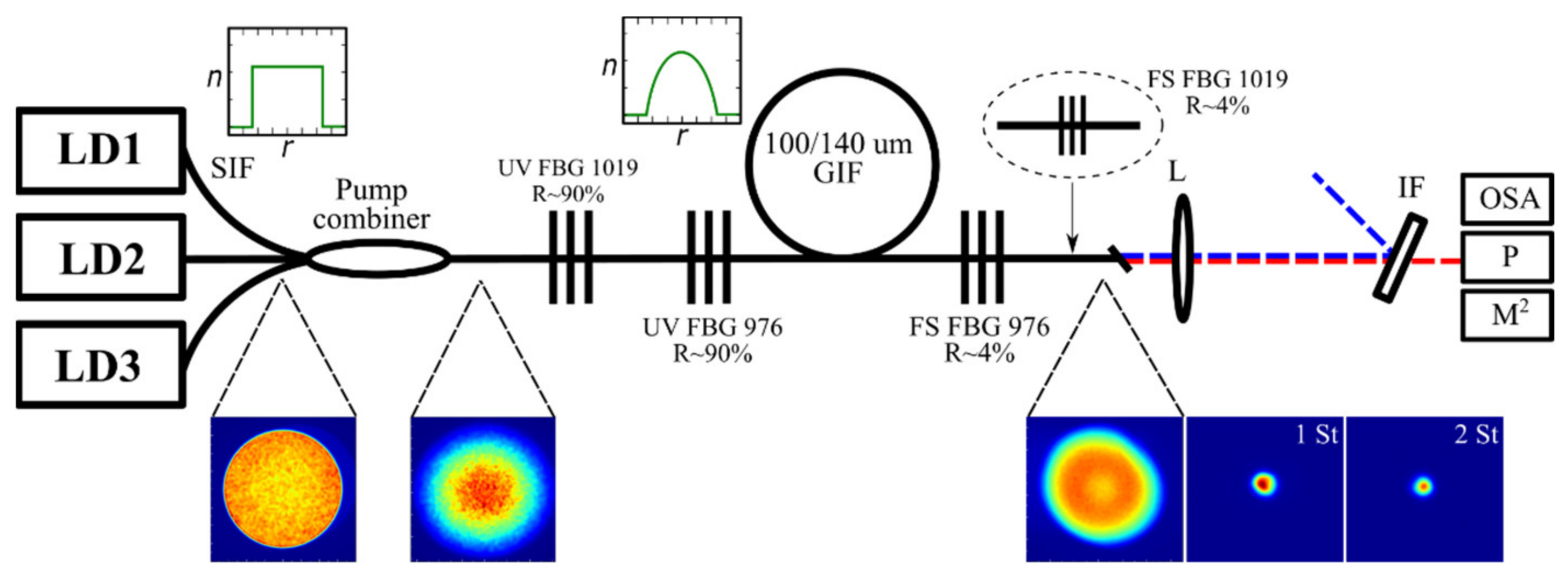
Three CW multimode laser diodes (LD1-3) pigtailed by a step-index fiber (SIF) with a 100 µm core are combined by a pump combiner and directly pump a 1 km graded-index fiber (GIF) with a 100 µm core, thus producing Raman gain in it; see
Figure 1. A resonator of the Raman laser is formed by an UV-inscribed highly reflective (R~90%) fiber Bragg grating (UV FBG) and a fs-inscribed output grating (FS FBG) with a low reflection coefficient (R~4%) at the corresponding Stokes wavelength, thus providing output coupling of the generated Stokes beam either of the first or second Stokes order. For the second Stokes order, instead of FS FBG, an angle-cleaved (~10 degrees) fiber end has been also tested for output coupling from the cavity. The laser output is collimated by a lens and characterized by a power meter (P), beam profiler (M
2) and optical spectrum analyzer (OSA), with the use of corresponding interference filters (IF) for selection of either the pump or the first and second Stokes beams. Two different LD sets with wavelengths of 915 or 940 nm with a total input power in GIF up to ~200 W have been used for pumping. The corresponding conversion of highly multimode (M
2~34) pump radiation at 915 nm into the first/second Stokes waves with wavelengths 950 (954)/976 (996) nm selected by corresponding FBG sets have been explored in the first case [
16], and 940 nm LD pump conversion into the first/second Stokes waves with wavelengths 976/1019 nm in the second case [
17].
Beam cross-sections for the multimode 940 nm LD pump radiation measured before and after the pump combiner in SIF and GIF, respectively, and after FS FBG, are shown together with the generated first (976 nm) and second (1019 nm) Stokes beam shape at the output. One can see that a significant reduction in the output beam size and corresponding improvement in the beam quality M
2 occurs at each stage of the pump to the first and second Stokes beam conversion. This improvement is mainly defined by the mode-selective properties of fs-inscribed FBGs, in which the modified refractive index is localized in a small area of 1 × 8 µm near the GIF core center, thus providing predominant reflection of the fundamental mode; see [
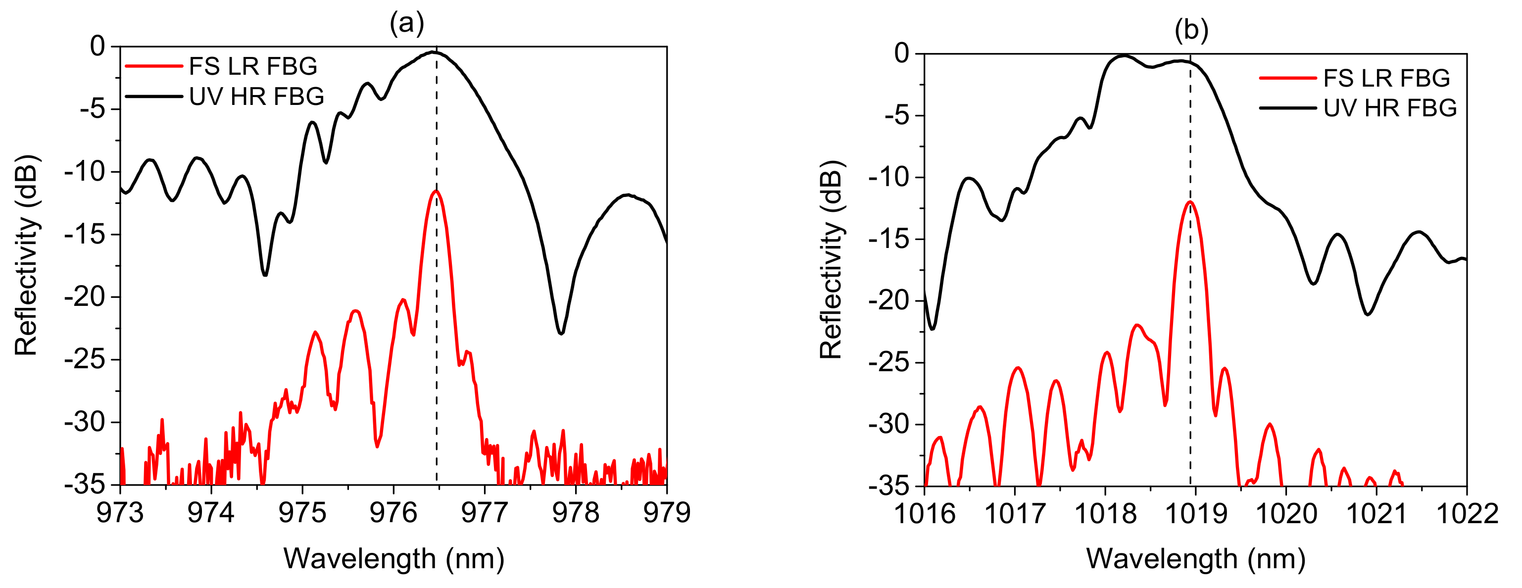
18] for more details. The reflection spectra of the 976 and 1019 nm FBG pairs employed in the scheme with 940 nm pump LDs are shown in
Figure 2a,b. One can see that the fs-inscribed (FS) low-reflection (LR) FBG has the main long-wavelength peak corresponding to the fundamental mode, whereas shorter-wavelength peaks corresponding to higher-order transverse modes are lower by ~10 dB. Note that in the case of high-reflection (HR) FBGs, the CW UV light modifies a significant part of the Ge-doped fiber core so that the difference between the main short-wavelength reflection peak corresponding to the fundamental mode and short-wavelength peaks corresponding to higher-order modes amounts to a few dB only. The obtained output characteristics in different cavity configurations are shown in the next sections.
3. Output Power/Efficiency in Different Schemes
As a first step, we compared cascaded generation in a linear cavity formed by highly reflective UV FBG and a mode-selective FS FBG with low reflection (R~4%) for both the first (S1) and the second (S2) Stokes wave—see
Figure 3a—with the configuration in which output FS FBG for the second Stokes wave is absent so that it starts generating in a half-open cavity configuration due to the random distributed feedback via Rayleigh backscattering; see
Figure 3b. We tested [
16,
17] and compare here two different wavelength sets—(1) 940 nm (LD)–976 nm (S1)–1019 nm (S2); (2) 915 nm (LD)–950 nm (S1)–976 nm (S2)—which show similar behavior. Although the generation threshold is lower in the case of the linear RFL cavity for the second Stokes wave (
Figure 3a), the slope efficiency for the second Stokes generation is higher in the case of the half-open random RFL (RRFL) cavity approaching approximately 37% and 43% for wavelength sets (1) and (2), respectively (
Figure 3b). Note that the second Stokes wavelength in case (2) sufficiently deviates from the corresponding Raman gain maximum (it is near 992 nm in the case of 950 nm 1st Stokes wavelength, whereas at 976 nm, the Raman gain coefficient is ~2 times lower [
16]); therefore, the generation threshold is shifted to higher pump powers in this case. Note that the maximum transmitted first Stokes power increases in configurations with the higher second Stokes threshold, whereas it behaves similarly in all cases below the second threshold. Above the second Stokes threshold, the transmitted first Stokes power is depleted more rapidly in the case of the RRFL cavity (
Figure 3b) in correspondence with the higher power and slope efficiency of the second Stokes generation in this case. This means that in the multimode fiber cavity with high losses, the optimal output reflection coefficient is closer to that for random Rayleigh backscattering, estimated to be more than one order of magnitude lower than that for FS FBG with R~4%. However, a more precise optimization of the output coupling may further increase the second Stokes output power in this configuration.
To test the wavelength tuning possibilities around the Stokes gain maximum, we compared different FBG sets in configuration (2) with 915 nm pumping and a half-open RRFL cavity for the second Stokes wave; see
Figure 4. The wavelength of the first FBG pair is shifted from 950 to 954 nm and the second HR FBG from 978 to 996 nm, exactly to the maxima of Raman gain for the first and second Stokes waves (Stokes shift corresponding to the maximum Raman gain amounts to 440–445 cm
−1 in 100 µm GIF [
16]). Since the difference in the first Stokes shifts is small, the two cases exhibit nearly the same first Stokes generation threshold and slope efficiency, whereas the maximum output power and slope efficiency for the second Stokes generation are sufficiently larger in the case of exact resonance corresponding to 996 nm. At the optimal conditions, the threshold value decreases and the slope efficiency of the second Stokes wave generation at 996 nm approaches that for the first Stokes wave generation (below the second threshold), amounting to around 70% and reaching a maximum power of 27 W, comparable to that for the first Stokes wave. Meanwhile, second Stokes generation at 978 nm (shifted by ~140 cm
−1 from the Raman gain maximum) exhibits around 17 W maximum power with higher threshold pump power and lower slope efficiency.
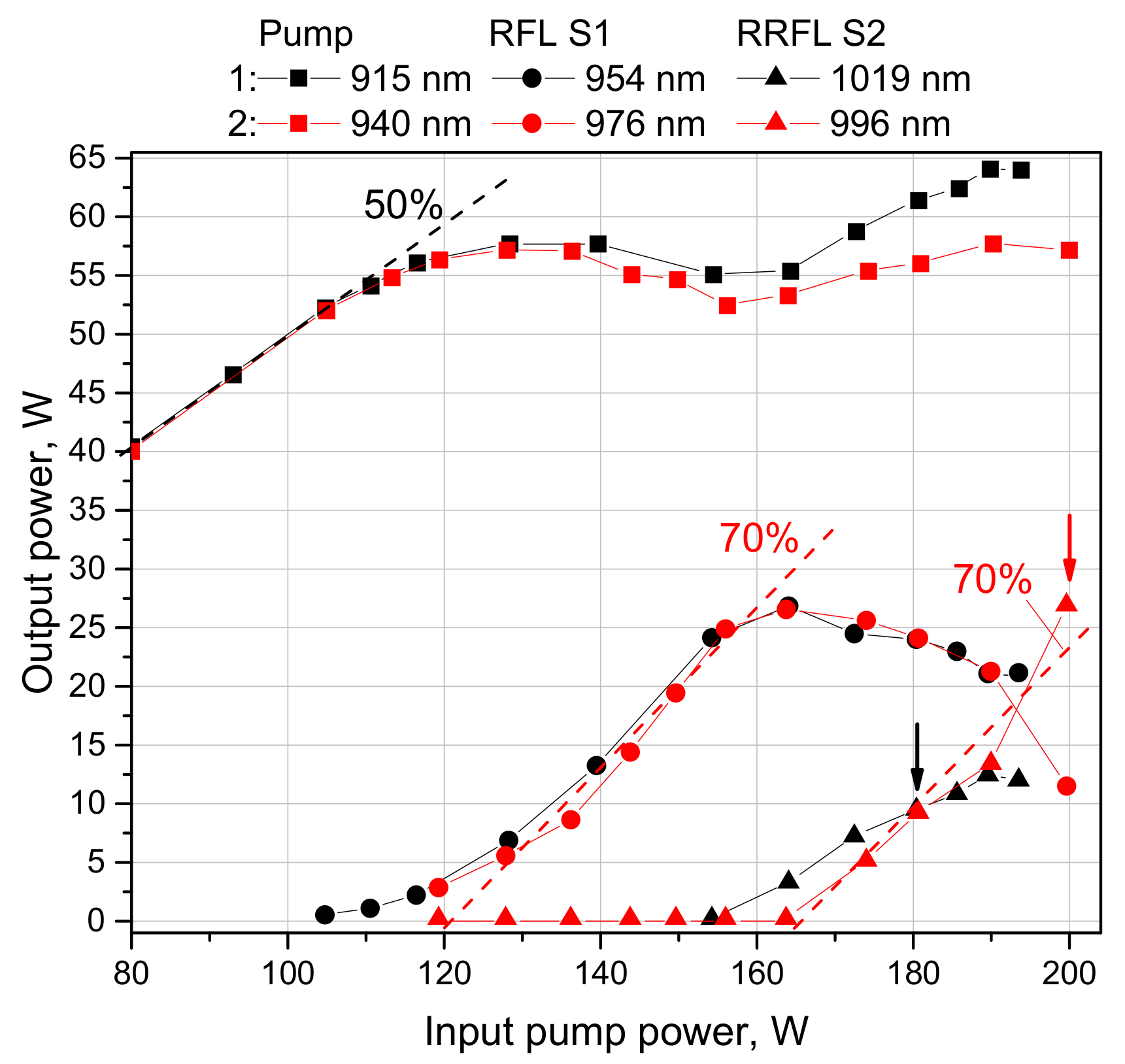
Let us compare the best results obtained for the cascaded Raman lasers with multimode 100 um GIF pumped by 915 and 940 nm multimode LDs and second Stokes output at 996 and 1019 nm, respectively. The results obtained at nearly exact resonances for the first and second Stokes waves provided by the linear RFL and half-open RRFL cavity, correspondingly, are summarized for both configurations in
Figure 5.
The comparison shows similar qualitative behavior for both configurations, with only a slight difference in power values. In both cases, the transmitted pump power grows nearly linearly with a slope of ~50% up to the first Stokes threshold, amounting to 105–110 W of input power. Above the threshold, the transmitted pump power starts to saturate and even to decrease, while the first Stokes power rapidly grows with a linear trend of slope efficiency to ~70% for both configurations. When the second Stokes threshold is approached, the first Stokes output starts to saturate and then decreases with increasing second Stokes power. At the same time, the residual pump power starts growing again above the second Stokes threshold. The second Stokes threshold amounts to 155–165 W of input pump power; above the threshold, the second Stokes power grows near linearly in both cases with similar slope, but around 180 W of input pump power, the slope becomes different in the two configurations. For the 996 nm output, it remains high enough (~70%), whereas for the 1019 nm, output it slows down to ~40%. We reveal that this slowing down is reasoned by the appearance of the third Stokes wave in this case. We identified that the low third Stokes threshold is reasoned by 1065 nm radiation coming from the pump 940 nm LDs; see [
17] for more details.
4. Output Spectra in Different Schemes
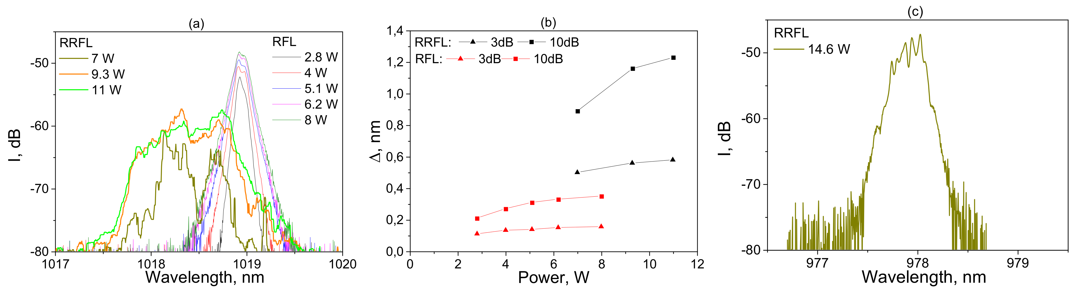
The measured output spectra of the second Stokes generation at 1019 nm in the RFL and RRFL cavity configurations are compared in
Figure 6a. One can see that the RFL spectra represent a relatively narrow single peak with exponential tails, which weakly broaden with increasing output power. At the same time, the RRFL spectra represent two peaks with unstable shape, which significnatly broaden with increasing power. In
Figure 6b, the RFL and RRFL widths at the −3 dB and −10 dB levels are compared, showing a principal difference in the width values and their dependence on power. The full width at half-maximum (−3 dB) at power ~10 W amounts to around 0.15 nm and 0.55 nm, repectively. The difference is mainly reasoned by the single and double peak structure of the RFL and RRFL spectra, correspondingly. In their turn, the laser spectra are defined by the reflection spectra of cavity FBGs; see
Figure 2b. In RRFL, the output narrowband FS FBG is absent and both reflection peaks of the broadband UV FBG take part in Raman generation, whereas adding narrowband FS FBG in the RFL configuration selects only one peak, thus leading to the laser spectrum narrowing and stabilization. Thus, the second Stokes spectral power density in the case of RFL is higher than that for RRFL. Note that in the case of 978 nm second Stokes generation in the RRFL cavity, the UV FBG has a single reflection peak, similar to the UV FBG spectrum shown in
Figure 2a. As a result, the generated RRFL spectrum narrows to a single peak (
Figure 6c), with the bandwidth decreased to around 0.2 nm at 14 W, which is comparable to the RFL bandwidth, which may be treated as a method for spectral power density enhancement for RRFL. At the same time, some fluctuations (especially near the top of the spectrum) remain.
5. Beam Profiles and Quality (M2)
The input and transmitted pump beam and the generated first- and second-order Stokes beams were characterized in terms of beam quality parameter M
2 and beam shape by a Thorlabs M
2-MS by using appropriate interference filters (IF) to select the corresponding wavelength. For measurement of the detailed output beam shape, we adjusted the focus on the fiber end facet given that the defocusing from the optimal focus point blurred the spatial details of the measured beam profile; for more details, see [
13] and citations therein.
The measured 2D projections of the beam intensity distributions are shown at corresponding points of the scheme in
Figure 1 with 940 nm LD, 976 nm and 1019 nm first- and second-order Stokes beams, respectively. The pump beam from individual LDs homogeneously fills the core of the SIF pigtail, with a transverse intensity profile similar to the index profile (the measured beam quality parameter is M
2~26). There are only weak signs of speckles, because of the large bandwidth (~5 nm) of LD radiation. After the mixing of three LD pumps in the fiber pump combiner, and propagation in ~2 m of GIF, the pump beam quality slightly degrades (M
2~30), whereas its transverse intensity profile takes a parabolic shape, mimicking the GIF index profile. This results from strong random mode coupling, leading to an equipartition of pump energy among all of the transverse modes [
13]. The transmitted pump beam is also nearly parabolic (M
2~34), but above the Raman threshold, it becomes depleted (with a hole in the center), owing to the first Stokes beam generation (its quality parameter M
2 changes from 1.7 to 1.9 with increasing Stokes power). The second Stokes beam generated after reaching its threshold is even narrower than the first Stokes beam (its quality parameter is M
2 = 1.3 − 1.4 depending on power and cavity configuration being very close for RFL and RRFL cavities). Note that the better beam quality in the case of the 1019 nm second Stokes wavelength than that for 996 nm (M
2~1.6) may also lead to the lower slope efficiency together with the lower third Stokes threshold in this case (see
Figure 5).
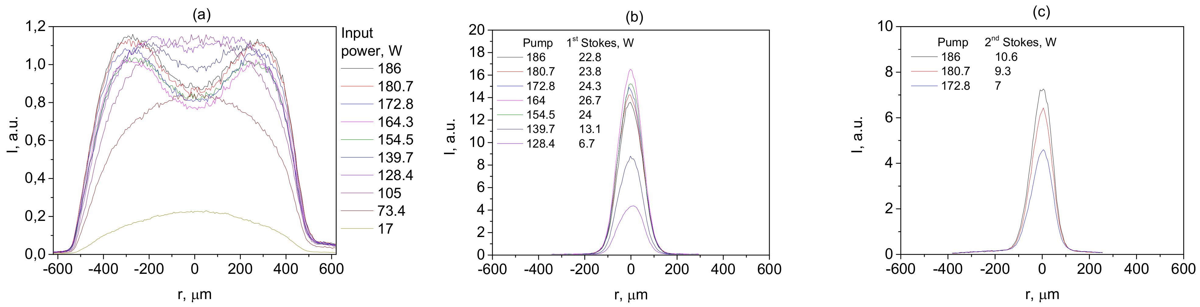
The beam profiles extracted from the 2D projections depending on power are shown in
Figure 7. The output pump beam profile changes from a parabolic to a near-rectangular profile above the first Stokes threshold; then, a dip is formed due to the inhomogeneous pump depletion at high-power Stokes generation (but the pump dip is broader than the first Stokes beam, which is reasoned by the strong influence of random mode coupling on the pump beam; see [
13] for more details). The first Stokes beam has a near-Gaussian shape defined by the FBG spatial filtering [
13], and it is almost unchanged with increasing its power and even when the second Stokes beam is generated, which, in turn, is Gaussian, growing without shape changes. At the same time, above the second Stokes threshold, the transmitted pump starts growing in amplitude, with the shape of the dip kept unchanged.
6. Discussion and Conclusions
Let us summarize the obtained results. In the studied system, highly multimode (M
2~30) 940 nm LD pump radiation up to ~200 W power coupled through a fiber pump combiner to a 100 um core graded-index fiber is serially converted into the first, second and third Stokes beam. A linear cavity composed of fiber Bragg gratings (FBGs) inscribed in the fiber core is formed to provide feedback for the first Stokes order, whereas for the second order, both the linear cavity consisting of two FBGs and the half-open cavity with one FBG and random distributed feedback (RDFB) via Rayleigh backscattering along the fiber are explored. LDs with different wavelengths (915 and 940 nm) are used for pumping, enabling Raman lasing at different wavelengths of the first (950, 954 and 976 nm), second (976, 996 and 1019 nm) and third (1065 nm) Stokes orders. Output power and efficiency, spectral line shapes and widths, beam quality and shapes are compared for different configurations. It is shown that the random DFB cavity of the Raman fiber laser (RRFL) provides higher slope efficiency of the second Stokes generation than that for the conventional RFL cavity; see
Figure 3. At the wavelength corresponding to the maximum Raman gain, the slope efficiency reaches 70% (close to that for the first Stokes wave) with output power up to ~30 W being limited by the third Stokes generation; see
Figure 5. Tuning within the broadband Stokes gain profile of the second Stokes by ~20 nm from the wavelength corresponding to maximum gain is demonstrated with the power reduction by factor 1.6; see
Figure 4.
While the quality parameter M
2 for the first Stokes beam at maximum power is close to 2, the beam quality parameter of the second Stokes beam approaches the diffraction limit (M
2~1.3) in the case of the 1019 nm wavelength both in the linear and half-open cavities, whereas the line is narrower (<0.2 nm) and more stable for the linear cavity with two FBGs; see
Figure 6. However, an optimization of the FBG reflection spectrum used in the half-open cavity allows this linewidth value to be approached, but the line shape in the case of the RRFL cavity remains less stable than that for RFL. In both cases, the measured beam profiles show the dip formation in the output pump beam, whereas the first and second Stokes beams are Gaussian-shaped and almost unchanged with increasing power; see
Figure 7. The qualitative explanation of such behavior in connection with the power evolution of the transmitted pump and generated first, second and third Stokes beams may be given on the basis of the power balance model, similar to that for single-mode cascaded RFL [
19]. When the input pump power reaches the first Stokes threshold, the transmitted pump power starts to saturate and then decreases, while the first Stokes power grows nearly linearly; see
Figure 5. When it reaches the second Stokes threshold, the pump power starts increasing again in order to compensate for the additional losses of the first Stokes wave power because of its conversion into the second Stokes wave. At the same time, the first Stokes power starts to decrease. When the second Stokes wave reaches the third Stokes threshold, the first Stokes output in turn starts increasing in order to compensate for the losses due to the conversion of the second Stokes wave into the third Stokes wave. Looking at the beam profiles (
Figure 7), the depletion of the highly multimode pump beam occurs inhomogeneously, whereas nearly single-mode first and second beams evolve without significant changes in the beam shapes, which are close to Gaussian. Thus, considering an averaging over transverse modes, the interaction of pump and Stokes components in the multimode case is similar to that for single-mode RFL [
19].
In conclusion, the treated scheme of the multimode cascaded Raman fiber laser represents a new type of LD-pumped fiber laser source that has the advantage of wavelength agility in comparison with conventional LD-pumped fiber lasers such as rare-earth-doped fiber lasers. It may generate in a broad wavelength range defined by available high-power multimode LDs. With the use of commercially available 9xx nm LDs, it is able to generate at almost any wavelength in the 950–1020 nm range, where the generation of conventional fiber lasers has serious limitations, such as photo-darkening [
20]. Consequently, wavelength tuning may be performed by means of both cascaded generation of the higher Stokes orders and detuning from the Raman gain maximum within the bandwidth of individual Stokes order (first or second). At the cascaded conversion, the beam quality is gradually improved to M
2 < 2 (1st Stokes) and M
2 < 1.4 (2nd Stokes) due to the Raman beam cleanup effect supported by the mode-selective properties of cavity FBGs [
13] or Rayleigh backscattering (RBS) in graded-index fibers. Herewith, the use of random DFB via RBS in an half-open cavity with one FBG for the second Stokes order allows one to increase its output power (~30 W) and slope efficiency (~70%) to the level characteristic for the first Stokes order. The third Stokes generation at ~1065 nm is shown to be also achievable, but this wavelength range is not so interesting as it is covered by a high-power Yb-doped fiber laser [
20]. Further development of multimode LD-pumped cascaded RFLs may be focused on their power scaling similarly to the first-order RFL [
21] and towards a shorter wavelength operation range with the use of 8xx nm high-power LDs.
The developed sources may find their application in biomedical diagnostics in the spectral range of <1 micron, frequency doubling [
22] to the spectral range of <500 nm and potential use in laser displays, frequency quadrupling to the spectral range of <250 nm and specific UV applications. The potential for wavelength tuning may also increase the application range, e.g., by the development of fiber-based sources that are alternative to the tunable systems based on Ti:Sa lasers.

 ,
, 