1. Introduction
Compared to most other types of laser, diode lasers are cheap and simple to use; they also have a high power and cover a large wavelength range. They have therefore become attractive light sources with versatile applications in many fields of optical technology and experimental physics, such as optical atomic clocks, precision measurement, astrophysics, and quantum communication [
1,
2,
3,
4,
5]. With this wide spectrum of applications, it is not surprising that lasers are used in very different environments, with one of the most demanding being space [
6].
In 1980, Lang and Kobayashi [
7] applied external-cavity feedback technology to diode lasers. The increased external cavity can narrow the laser line width, and The wavelength can be tuned by changing the external cavity length. In The following years, Soviet scientists, for The first time, used a diffraction grating to feed back part of the output light of the diode laser to the active region, narrowing the linewidth of the laser to 1.5 MHz [
8]. Common external-cavity diode laser (ECDL) designs such as the Littrow [
9,
10] and Littman–Metcalf configurations [
11,
12] use diffraction gratings for wavelength selection. Those lasers require precise alignment and are therefore sensitive to acoustic and mechanical disturbances, particularly when a spring-loaded kinematic mount is used to align the grating or feedback optics [
13]. Another design uses a narrowband interference filter (IF) placed in a linear cavity as a frequency-selective component [
14,
15,
16]. Because The wavelength of the transmission maximum depends on the angle of incidence, where the angle is the angle of incidence and the maximum wavelength is the transmitted wavelength at normal incidence, the wavelength can be tuned by turning the filter. This leads to a sensitivity of
nm/mrad, which is 60 times better than that of the Littrow configuration. Thus, the laser design is in principle less sensitive to mechanical vibrations and disturbances. With these advantages, the interference-filter configuration was chosen for the PHARAO [
17,
18] and SOC2 [
19] projects for space laser systems.
As the atomic clock with the highest performance index in the world, the measurement accuracy of a strontium atomic optical clock has entered the order of
[
20]. In the microgravity environment of space, the performance of optical clocks is expected to be further improved [
21]. The National Time Service Center (NTSC) of China is conducting research on the space Sr atomic optical clock. In the strontium atomic optical clock system, the wavelength of the clock transition
is 698 nm, and The natural linewidth is only 1 mHz. The linewidth of the detection light must reach the order of Hz or even sub-Hz. We use an ultra-narrow linewidth laser to detect the clock transition line. The ultra-narrow linewidth laser (also called clock laser) was obtained by locking the laser frequency to a high-finesse optical reference cavity by means of the Pound–Drever–Hall (PDH) technique [
22]. The ECDL developed in this paper is used as the light source of an ultra-narrow linewidth laser system which is aimed to has a free-run linewidth at the level of 500 kHz or less. At present, commercial semiconductor lasers at 698 nm have wavelength tuning capabilities up to 10 nm. However, due to the use of an elastically loaded adjustment device, the structure is not very stable and usually needs to be readjusted every month to ensure good optical feedback and correct wavelength. Although The laser developed in this paper does not have a wide range of tuning capabilities, it has a stable structure and is one of the best choices to meet our special applications.
The objective of the present study is to develop and characterize a prototype of a 698 nm interference-filter external-cavity diode laser (IF-ECDL). The developed ECDL is compact and robust, and it will be planned for use in China’s space Sr atomic light clock system in the future.
2. Working Principle of the IF-ECDL
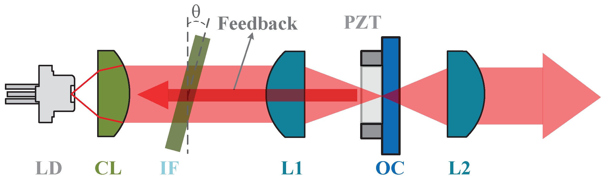
In the IF-ECDL, the interference filter provides wavelength selection, and a partially reflective mirror provides optical feedback, as shown schematically in
Figure 1. The interference filter is composed of alternating layers of dielectric material that can transmit a narrow frequency band while reflecting the light of other wavelengths. The narrowband interference filter is actually a thin Fabry–Perot etalon with only one transmission peak in the visible range, also known as a line filter. The bandpass section of an interference filter is made by the repetitive vacuum deposition of thin layers of partially reflecting dielectric compounds on a glass substrate. Dielectric layers are arranged to form reflective cavities. The spacer region is designed to be
thick, where
is the central wavelength of the filter. This allows light that meets the reflection boundary conditions to be reinforced and transmitted by the cavity. The rejected light is reflected by the layers of dielectric material. The laser light generated by the semiconductor laser is collimated into parallel light by a lens, and then incident on the interference filter at a certain angle
. Using the multi-beam isotropic interference theory, the wavelength
at the peak of the transmittance is
where
is the interference filter’s effective index of refraction, and
is the transmission wavelength value of the narrow-band filter when the beam is normally incident, and is also the maximum limit wavelength value in the tuning range of the narrow-band filter.
Assuming that the outgoing light intensity of the bare laser diode is
I, then the total light intensity transmitted through the interference filter is given by the Airy formula
where
is the fineness of the IF. By rotating the angle of the interference filter placed in the ECDL resonator cavity with respect to the laser, the wavelength of the laser exiting the IF-ECDL is tuned. Using the IF for frequency selection, a single longitudinal mode laser can be obtained.
3. Design of the IF-ECDL
3.1. Optical Design
A semiconductor laser diode (LD) with a central wavelength of 698 nm is anti-reflection coated on its output facet and is combined with an external cavity, leading to a large tuning range for the wavelength. The cavity length of the LD is 750 m, and The reflectance of the two surfaces are 1 for the back face and for the AR coated face. The light coming from the LD is collimated by a collimating lens (CL) with a focal length of 4.02 mm and a numerical aperture of 0.6. To collect as much light from the diode as possible, the CL must have a large numerical aperture.
The optical feedback is provided by a combination of a cat’s-eye lens (L1) with a focal length of 15.29 mm and a partially reflective out-couple mirror (OC) with 30% reflectivity in focal distance. This cat’s-eye configuration is less sensitive to misalignments of the OC compared to the case of feedback with no such lens. A cat’s-eye reflector decreases the sensitivity to optical misalignment and maximizes the feedback efficiency. The overall external-cavity length from the LD output facet to the OC front facet is 50 mm and corresponds to an axial mode spacing of
The optical length of the external cavity is tuned with a piezotube (PZT) of 9 mm in length and with internal and external diameters of 5 and 10 mm, respectively. Applying a voltage of 100 V to the PZT changes the length of the external cavity by 1.4
m. For a given optical mode, a variation
in the optical path
l of the external cavity yields a relative frequency detuning of
allowing the PZT to tune the laser frequency with a response of
MHz/V.
The final optical component in the optical path is a re-collimating lens (L2) with a focal length of 11 mm, which is used to re-collimate the out-coupled laser. To narrow the output beam, the L2 focal length is chosen to be smaller than the L1 focal length.
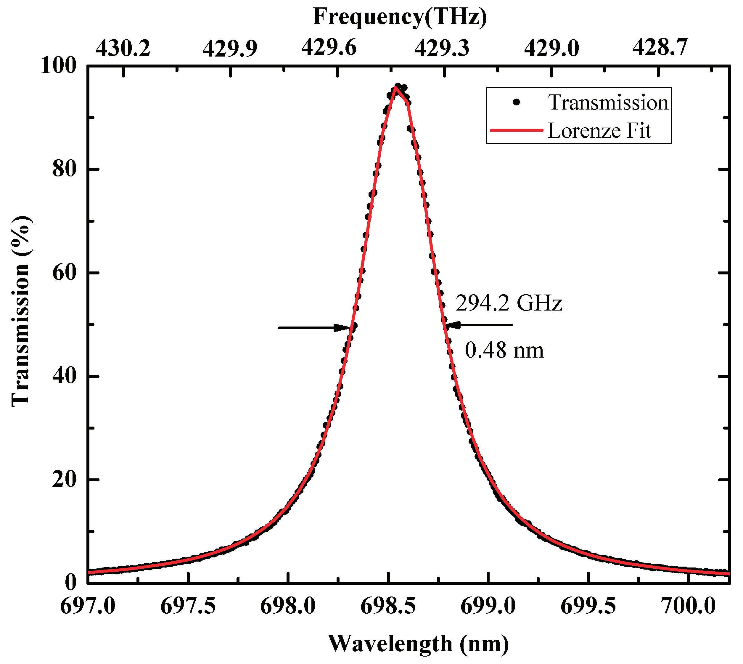
An IF is placed inside the external cavity between the CL and L1 and is used for coarse wavelength tuning. It is part of a resonator that forces the laser to maintain a stable single mode and reduces the linewidth. The IF is made of a substrate that is coated with many dielectric layers on one side and anti-refection coated on the other side [
23]. It has a 0.48 nm super-narrow passband and a peak transmission of 96%, and its measured spectrum is shown in
Figure 2. The wavelength of the transmitted light is changed by adjusting the angle of the IF. Compared with the Littrow and Littman–Metcalf configurations, the IF and cat’s-eye reflector replace the grating used to select the laser wavelength and form an external cavity, making it relatively easily to adjust the laser frequency and optimize the optical feedback. Furthermore, because The IF and cat’s-eye reflector are insensitive to the incident angle [
15], the present design has a higher mechanical stability than those of the Littrow and Littman–Metcalf configurations.
3.2. Structural Design
The aim of the structural design of the ECDL is to provide a good mechanical environment for the optical components installed inside. The design should be able to resist external mechanical inputs, thereby ensuring the reliability and stability of the laser. Structural factors such as structural stability, machining and assembly accuracy, mechanical robustness, weight, and size should be considered in the design process.
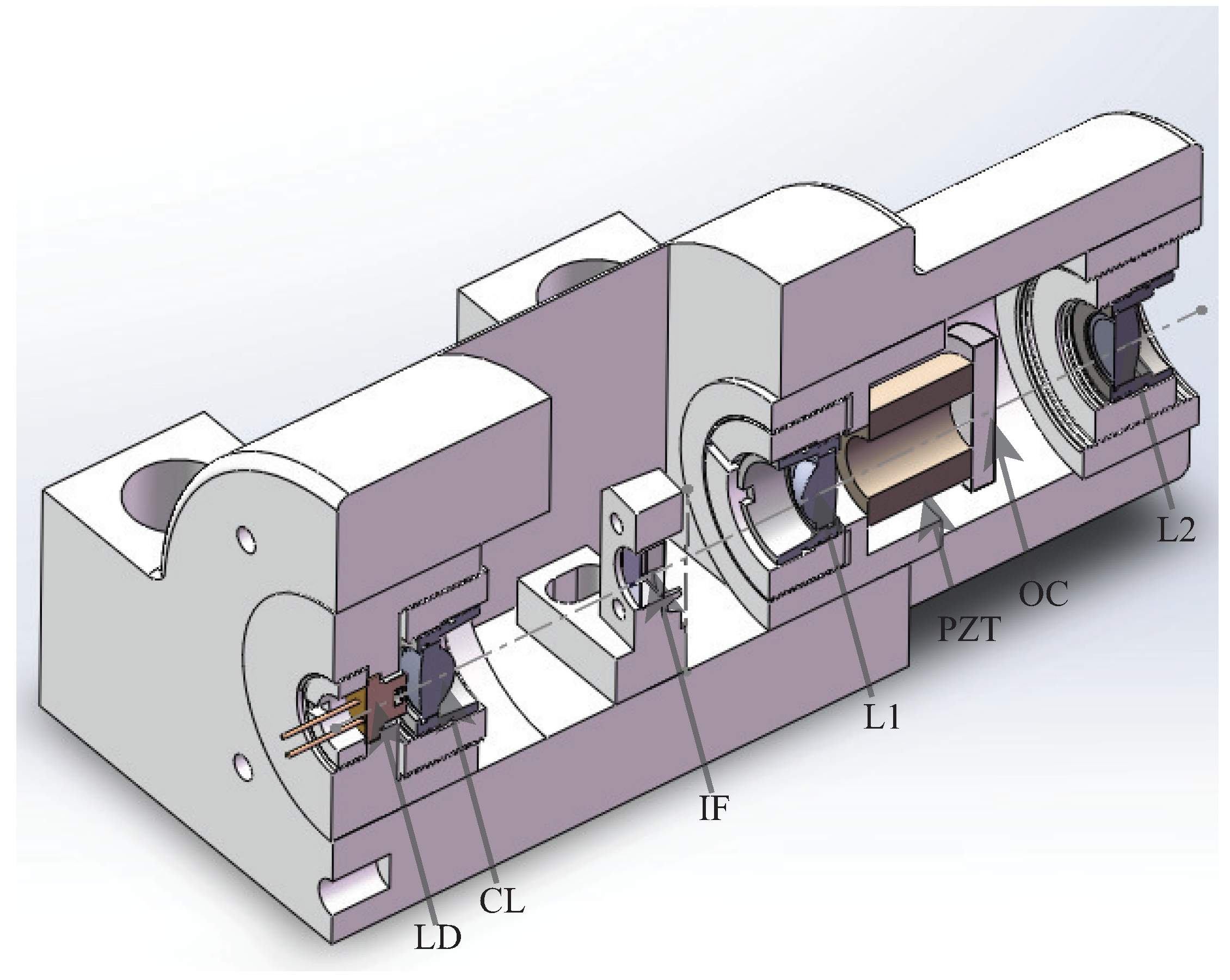
The mechanical structure of the ECDL is shown in
Figure 3. The mechanical parts comprise a laser base, a mount for the LD and CL, a mount for L1 and the PZT, a mount for L2, and a mount for the IF. In The present design, most of the parts are made of aluminum alloy, which is relatively light and has a consistent rate of thermal expansion, thereby reducing the effects of thermal stress on the optical components. The choice of material in this design was made primarily for principle verification; other material options that satisfy environmental requirements include AlSiC and Ti.
To ensure long-term stable laser operation suitable for space applications, the connections among all the components are rigid, and The design avoids any spring-loaded adjustment. The LD is fixed rigidly to its bracket by a retaining ring. Except for the IF, the mounts of the other optical components are cylindrical structures with the same outer diameter. All the mounts are inserted into the laser base after the components are mounted and locked by M2.5 screws. After setting the required angle of the IF holder, it is fixed to the platform of the laser base by two M3 screws. All the lenses, including CL, L1, and L2, are adjustable along the optical axis only; they are adjusted to their required positions and then fixed in place using slow-setting glue.
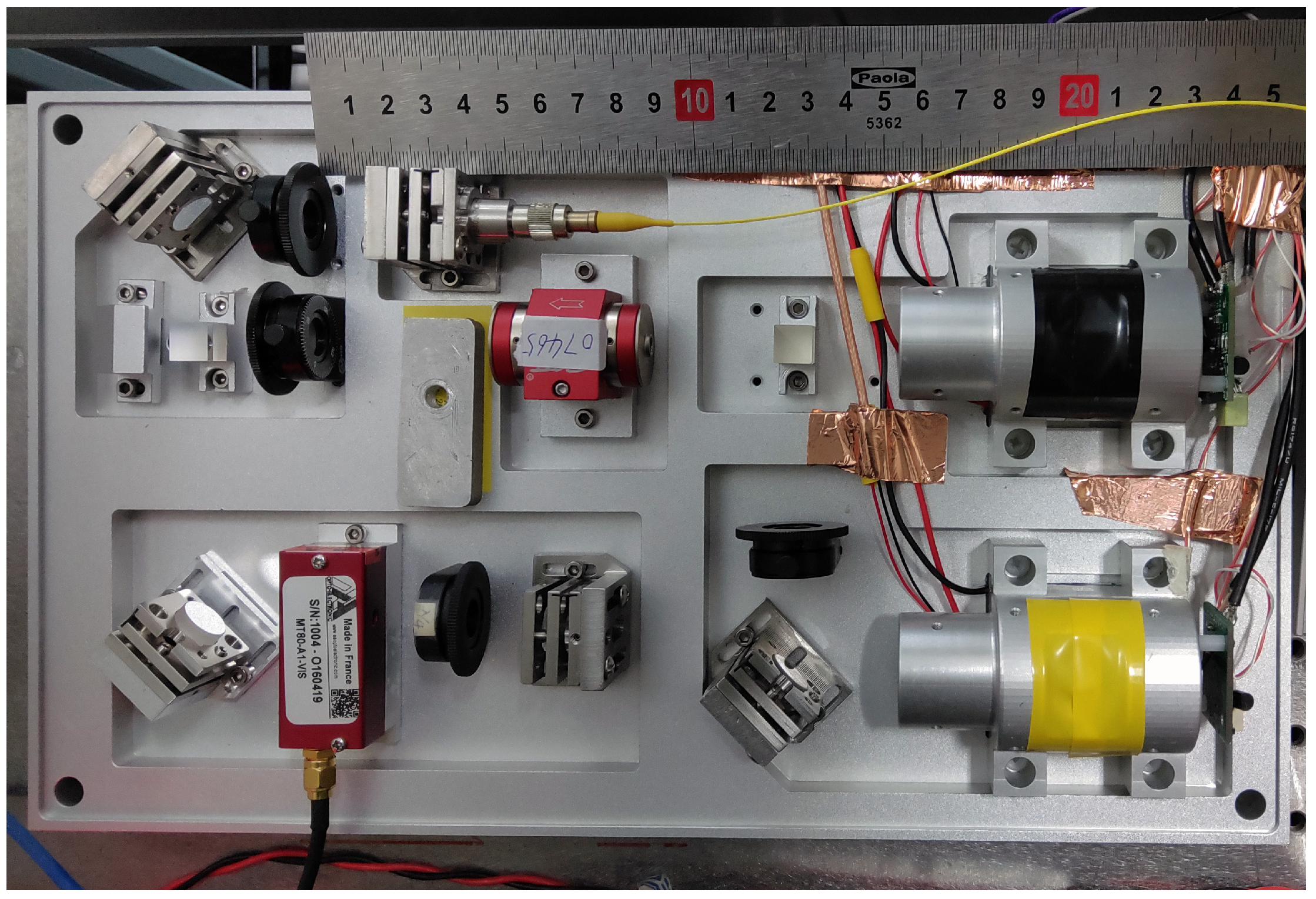
The laser base is machined from a solid aluminum block to ensure that the laser is stable, robust, and insensitive to outside interference.
Figure 4 shows a photograph of the laser, the outer envelope of which is 75 mm × 65 mm
mm. Because The laser frequency depends on the length of the cavity, precise temperature control of the laser is necessary [
9,
24]. A small hole with a diameter of 3 mm and a depth of 5 mm is found at the end of the laser base close to the LD; in this hole is placed a negative-temperature-coefficient thermistor for detecting variations in temperature of the LD. A Peltier thermoelectric cooler with dimensions of 40 mm × 40 mm
mm is attached to the surface of the laser base to stabilize the temperature of the cavity and LD. To ensure a laser output height of 20 mm from the optical table, this ensemble is fixed on the optical platform with four M4 Teflon screws. The optical platform acts as a heat sink, as illustrated in
Figure 4.
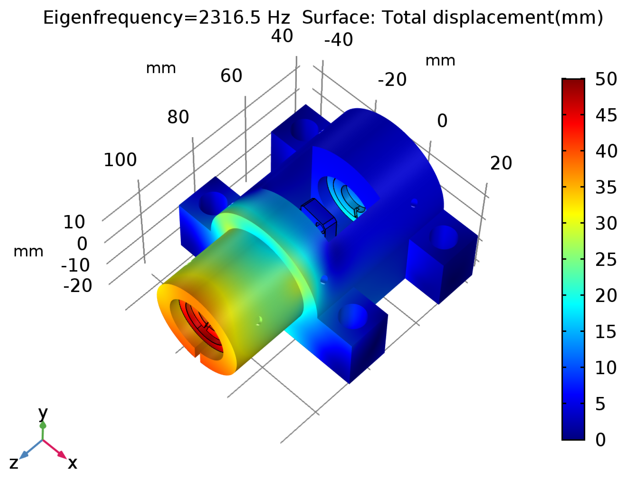
3.3. Simulation of Eigenmodes and Stress Distribution
The structural design of the laser should have a high fundamental frequency and good dynamic characteristics to prevent structural damage caused by resonance of the low-frequency coupling during launch. We used finite element modeling to verify that the ECDL design is satisfactory. To reduce the amount of data needed for analog operation, we simplified the laser model appropriately. The model retains the physical structure of the laser, the optics, and The mounting brackets, but omits details such as chamfers and fillets. The overall structural material of the laser is aluminum alloy, the optical lens material is fused silica, and The PZT material is PZT-5A; the properties of these materials are given in
Table 1. The simulation results are shown in
Figure 5, where the lateral rocking frequency of the first eigenmode is 2316 Hz. Because The first-order natural frequency of the module at the aerospace standard component level exceeds 70 Hz, the modal analysis shows that the design meets the requirements. However, the eigenfrequency is too high, indicating that the structural design of the laser requires further optimization.
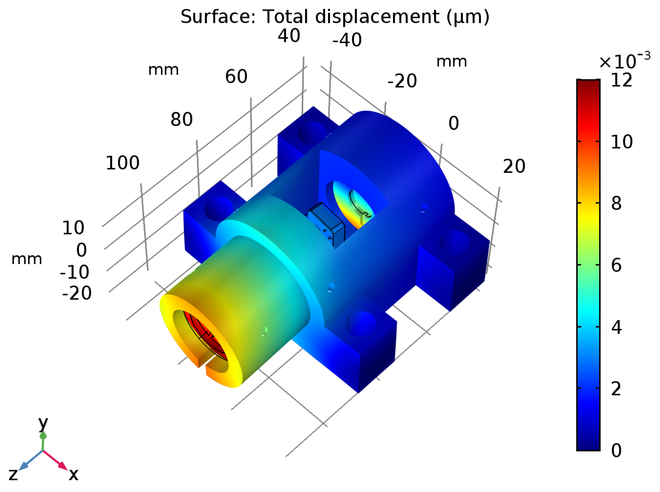
Another issue is that the gravitational environment differs between space and the laboratory. The lab-mounted laser undergoes a tiny deformation once in microgravity. To reduce this effect, we adopted an integrated external cavity structure to reduce the relative mechanical deformation as much as possible. In addition, no adjustable elastic mechanical structure was used. The cantilever length and mass are reduced as much as possible while maintaining the mechanical strength.
Figure 6 shows the displacement of the ECDL under a vertical acceleration of 1 g. The maximum deformation clearly occurs at L2 but is only 0.01
m. When the optical board with the laser mounted is placed face up and back up, the performance of the optical system remains the same, indicating that this small deformation has no effect on the performance of the ECDL. We also analyze the deformation of two major components, IF and OC, that affect ECDL performance under the action of gravity along the optical axis (
z axis). Among them, the deformation of IF is 0.003
m. This deformation is mainly a translation in the direction of light transmission and has no effect on the angle of the IF. The deformation of OC is 0.005
m. This deformation will increase the length of the external cavity and affect the frequency of the output laser. This slight shift results in a frequency change of only 0.4 GHz. This deviation can be corrected by adjusting the voltage of the PZT.
4. Test Results
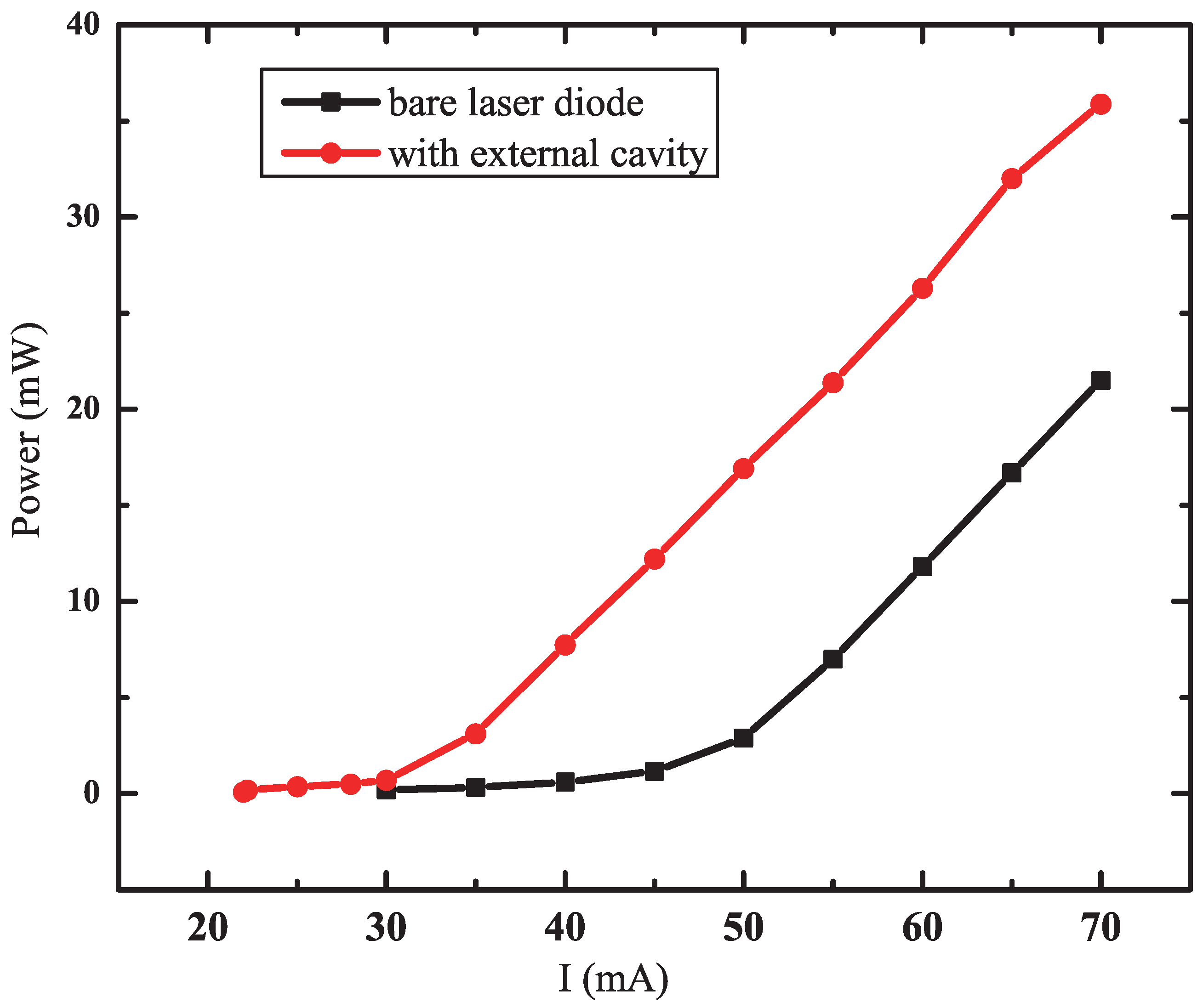
After adding the external cavity to the diode laser, iterative focal adjustment and external-cavity alignment were implemented to optimize the optical feedback. Optimum alignment was accomplished when the threshold was reduced to a minimum [
25]. The variation of output power with laser diode current as measured using an optical powermeter is shown in
Figure 7 both with and without an external cavity. The threshold current of the ECDL is 30 mA, and The diode current shifts the laser output power by 0.91 mW/mA. As can be seen in
Figure 7, the threshold current was reduced by approximately 10 mA compared to the bare tube, and The output optical power was increased by 15 mW at a laser current of 65 mA. The output surface of the laser diode we used was coated with an anti-reflection coating, and The reflectivity was only
orders of magnitude. In principle, the main reason for increasing the output laser power after increasing the external cavity was to reduce the threshold current: (1) adding an external cavity is equivalent to an increase in cavity length; (2) introducing optical feedback to help increase the stimulated emission suppresses the spontaneous radiation. These results indicate that the external-cavity semiconductor laser of the present design achieves strong optical feedback and completes good alignment [
25].
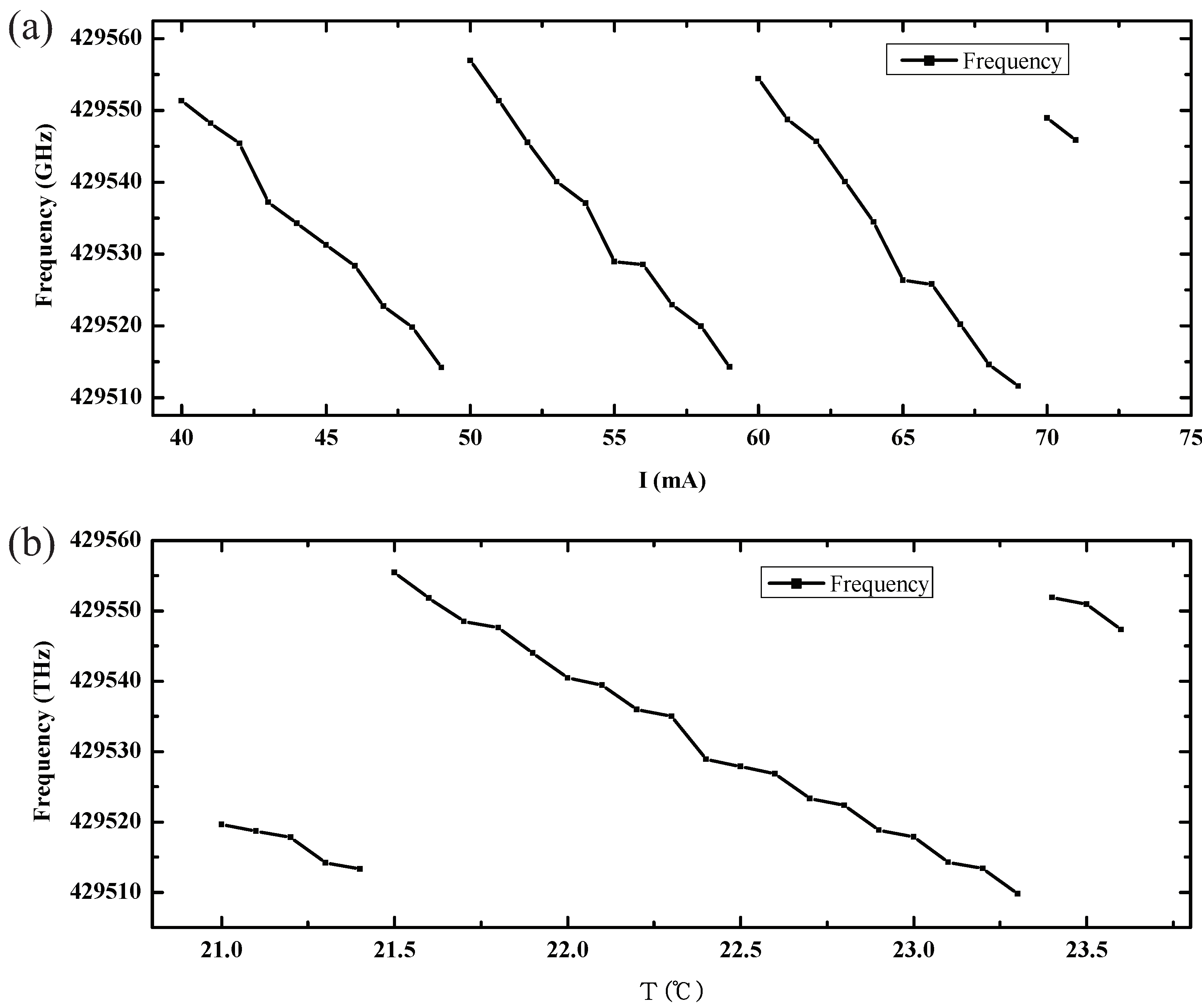
The effect of injection current and temperature on the output wavelength of the ECDL was investigated. It can be seen in
Figure 8 that, like the laser diode, the ECDL also has a mode hopping interval. It is necessary to avoid this mode hopping interval when the laser is working. The wavelength dependence on the injection current at a fixed temperature of 22.3
C is shown in
Figure 8a. The current adjustment range corresponding to the ECDL’s no mode hopping interval is about 9 mA, and the corresponding frequency varies by approximately 43 GHz. From this, the frequency tuning rate of the injection current can be calculated to be approximately 4.8 GHz/mA.
Figure 8b shows the wavelength dependence on temperature at a fixed current of 64 mA. The coefficient of the frequency with temperature is 25 GHz/
C, and The non-mode hopping interval is 1.7
C. The laser frequency can be tuned over a wide range by changing the temperature, but this adjustment is very rough, and it takes a long time for the laser temperature to become completely stable. With increasing injection current or temperature, the wavelength increased (frequency decreased). This is because the temperature of the laser diode increases as the injection current increases. The effective refractive index increased, leading to an increase in the optical length of the internal cavity. When the wavelength increased and entered the edge of the range selected by the interference filter, the operating mode competed with neighboring modes and mode hopping occurred. The range of continuous non-hopping mode is mainly determined by the FSR of the internal cavity and the full width at half maximum (FWHM) of the interference filter.
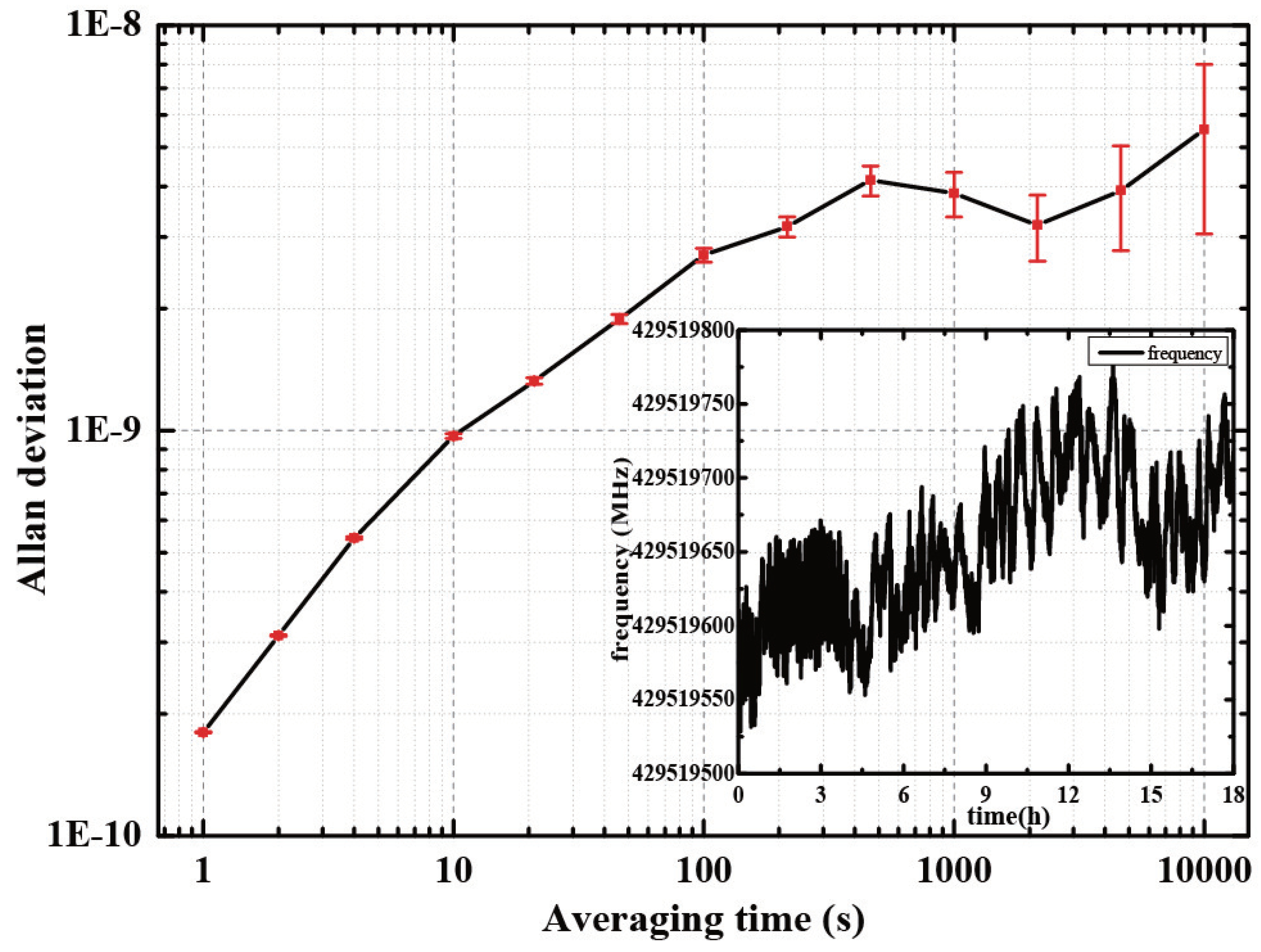
To determine the long-term stability of the IF-ECDL, we used a wavelength meter (WS7; HighFinesse) to monitor the frequency fluctuations of the laser during free running. The results obtained over a period of 18 h indicated good passive long-term stability, and The maximum deviation in laser frequency was only 200 MHz.
Figure 9 shows the frequency stability of the ECDL derived from the Allan deviation. The measurements were conducted in an air-conditioned laboratory in which the temperature fluctuated by roughly 1
C about an average of roughly 22
C.
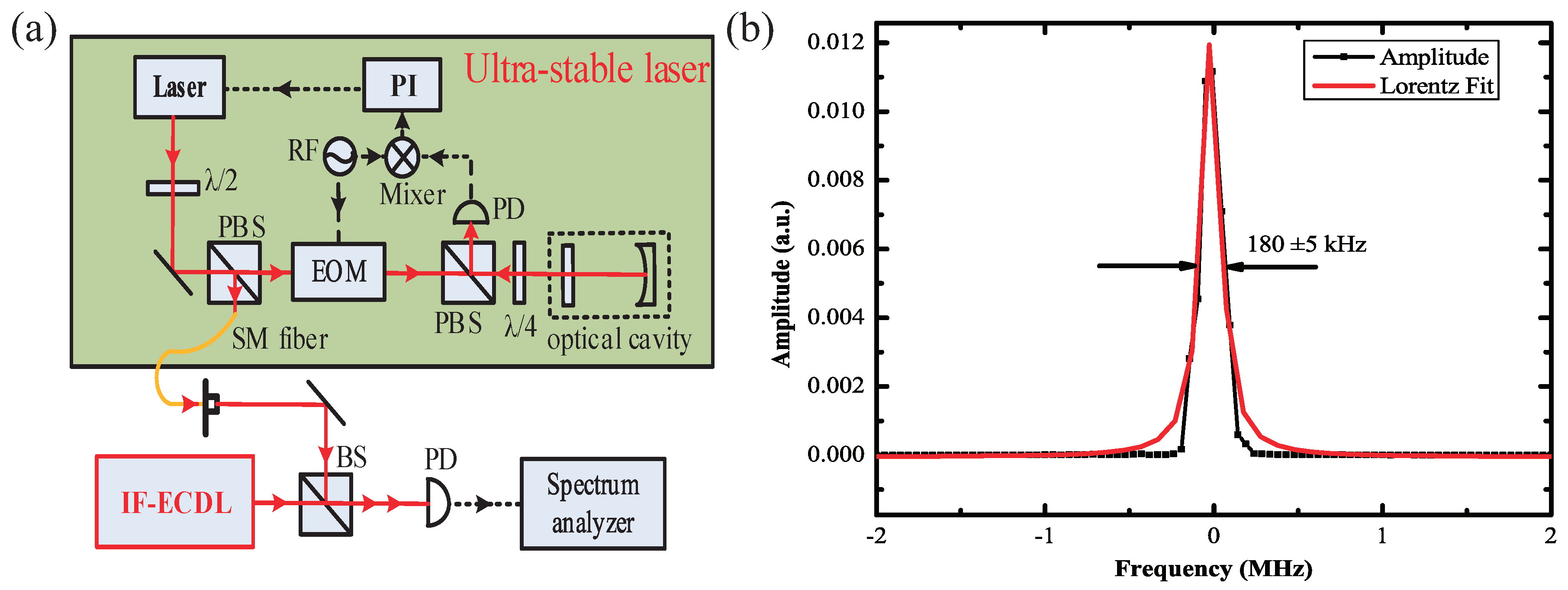
To determine the linewidth of the ECDL, we performed an optical heterodyne beat experiment involving the IF-ECDL and a 698 nm ultra-stable laser with an ultra-narrow linewidth. The spectrum of the beat signal is shown in
Figure 10b. The full width at half maximum of the Lorentzian fit is 180 kHz. The linewidth of the ultra-stable laser is only
Hz [
26], and this was obtained by locking the laser frequency to a high-finesse optical reference cavity by means of the Pound–Drever–Hall method [
22]. The linewidth of the beat signal can be considered to be the linewidth of the IF-ECDL because the latter is far wider than the linewidth of the ultra-stable laser. Therefore, the linewidth of the ECDL is roughly 180 kHz.

 ,
, 


