Article

Tuning of Fiber Optic Surface Reflectivity through Graphene Oxide-Based Layer-by-Layer Film Coatings

1
INESC TEC and Department of Physics and Astronomy, Faculty of Sciences, University of Porto, Rua do Campo Alegre 687, 4169-007 Porto, Portugal
2
CEFITEC, Departamento de Física, Faculdade de Ciências e Tecnologia, Universidade Nova de Lisboa, 2829-516 Caparica, Portugal
*
Author to whom correspondence should be addressed.
Photonics 2020, 7(1), 11; https://doi.org/10.3390/photonics7010011
Submission received: 13 December 2019 / Revised: 11 January 2020 / Accepted: 15 January 2020 / Published: 18 January 2020
(This article belongs to the Special Issue Advanced Optical Materials and Devices)

Abstract

:
The use of graphene oxide-based coatings on optical fibers are investigated, aiming to tune the reflectivity of optical fiber surfaces for use in precision sensing devices. Graphene oxide (GO) layers are successfully deposited onto optical fiber ends, either in cleaved or hollow microspheres, by mounting combined bilayers of polyethylenimine (PEI) and GO layers using the Layer-by-Layer (LbL) technique. The reflectivity of optical fibers coated with graphene oxide layers is investigated for the telecom region allowing to both monitor layer growth kinetics and cavity characterization. Tunable reflective surfaces are successfully attained in both cleaved optical fibers and hollow microsphere fiber-based sensors by simply coating them with PEI/GO layers through the LbL film technique.

1. Introduction

Graphene is a very compelling material that has recently become a trending topic [1]. Optical, mechanical, and thermal properties of graphene have been explored in many applications [2] such as, field effect transistors [3], transparent conductive films [3], production of clean energy devices [4,5], and sensor devices [6,7]. Graphene nanosheets with single- or multi-layers can be obtained through mechanical exfoliation and epitaxial chemical vapor deposition [8]. However, these fabrication methods, although yielding high-quality graphene, are not effective for large scale manufacturing. As an alternative, graphene oxide (GO) has been revealed to be a feasible alternative with outstanding properties offering easier synthesis methods. Actually, GO is a graphene precursor which can be synthesized by several methods such as those used by Brodie [9], Staudenmaier [10] or Hummers [11]. The oxygen-containing functional groups of GO creates hydrophilicity, which allows GO to be exfoliated in many different solvents and dispersers, including water [2]. Additionally, hydrophilicity allows GO to be used for uniform thin-film deposition onto solid supports [12].
Recently, the properties of graphene and GO have been explored in optical fiber sensing, offering many advantages over conventional sensing strategies due to its electromagnetic noise immunity, biocompatibility, resistance to harsh environments and electromagnetic passiveness [13]. Graphene and GO conductivity are modified as a function of surface adsorption, resulting in an effective refractive index variation. This feature was explored for gas [14,15], volatile organic compounds [16,17], biological compounds [18,19], and humidity [20] detection. Additionally, graphene also has been explored as diaphragm material for fiber sensors based on Fabry–Perot interferometry. Chemical vapor deposition (CVD) synthesized graphene, adsorbed to a sensing structure through Van der Waals forces, was addressed for pressure [21], temperature [22], and acoustic pressure sensing [23], for example.
Here, the possibility of using GO layers as a coating material for enhancing the sensing properties of optical fiber-based sensors is studied. To achieve that, multilayers of polyethylenimine (PEI) and GO are deposited onto cleaved single-mode optical fibers, using the layer-by-layer technique, and layer adsorption kinetics is accessed by in-situ reflectivity measurement. To investigate the possibility of using GO as an enhancer material in optical fiber sensors, hollow fiber microspheres are used as supports for GO layer deposition. This sensing structure is widely explored in literature for hydrostatic pressure [24,25] lateral load [26], and strain [27,28] sensing. Under this compliance PEI/GO multilayers are deposited in hollow microsphere-based sensors and the reflective features of these layers are obtained. Taking a more general point of view, we demonstrate that, with the methods used, one can attain the in situ adsorption kinetics curves of GO layers, meaning that this method can be applied to other molecules.

2. Materials and Methods

2.1. PEI/Graphene Oxide Deposition

Graphene oxide deposition was achieved using the layer-by-layer (LbL) technique. This is a simple and fast thin‑film fabrication technique that uses intermolecular interactions between oppositely charged polyelectrolytes to assemble a multilayer structure. It was shown that the main driving force accounting for the formation of LbL films arises from electrostatic interactions between oppositely charged polyelectrolytes, although Van der Waals, hydrogen and covalent bonding also are known to contribute, depending on the molecular species involved [29,30]. Noteworthy, the LbL technique presents a major advantage over other techniques of allowing for thin-film deposition in highly complex support geometries, as in the case of hollow microspheres.
The deposition process was started by removing biological residues together with surface hydrophilization of the substrates using a solution composed of sulfuric acid (H2SO4) and hydrogen peroxide (H2O2). This procedure promotes the adsorption of positively charged polyelectrolytes. Afterwards, the air-dried substrates were immersed in a polycationic solution of PEI, with a concentration of 2 × 10⁻⁴ M, for around 60 s. The excess of polyelectrolytes that were not adsorbed were removed by rinsing in Milli-Q water for around 20 s. After air-drying for around 2 min, the substrates were immersed in the polycationic solution of GO, of the same concentration as the PEI solution. This process was repeated to build the required PEI/GO bilayers.

Graphene Adsorption Kinetics

GO adsorption kinetics was investigated using cleaved optical fibers. The fibers were coated with PEI as previously described, and then immersed in the GO solution for about 15 h. The reflectivity was measured in intervals of 5 min. The experimental setup, presented in Figure 1, was composed by a broadband optical source, with a bandwidth of 100 nm centered at 1550 nm, an optical circulator that allowed us to attain the reflected light, connected to an optical switch and an optical spectrum analyzer (OSA). The optical switch allowed us to guide the input light to the corresponding fiber and to receive the reflected light back from the circulator, which was connected to the OSA. A reference fiber also was connected to the optical switch to eliminate the influence of optical source fluctuations on the output signal.

2.2. Hollow Microsphere Fabrication and Operation Principle

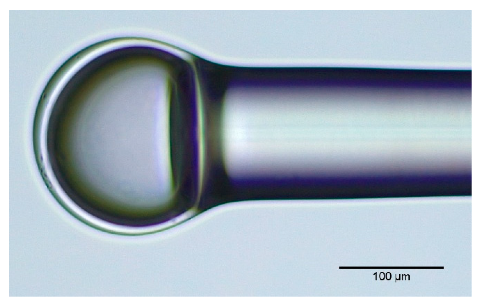
The fabrication process of hollow fiber microspheres involves several steps, as presented previously in the literature [31]. The first step consists of fusion splicing a standard single mode fiber (SMF) to a silica capillary with an outer and inner diameter of 125 and 57 µm, respectively. To minimize optical losses in the spliced region due to deformation of the capillary, the fusion splice was done using a manual mode with the electric arc displaced from the capillary. Afterwards, the capillary was cleaved to the desired length, partially controlled using a stereo microscope. By applying two successive electric arcs with higher electric arc time and power at the top of the capillary, the microsphere was formed. The final structure is presented in Figure 2.
Considering that the reflectivity at each air/silica interface was very low (less than 4%), the hollow microsphere was approximated to a three-mirror Fabry–Perot interferometer, since higher-order interferences can be neglected. The reflected intensity signal can be approximated by Equation (1) [32]:
I R ( λ ) = I 1 + I 2 + I 3 2 I 1 I 2 cos ( ϕ 1 ) 2 I 2 I 3 cos ( ϕ 2 ) + 2 I 1 I 3 cos ( ϕ 1 + ϕ 2 ) ,
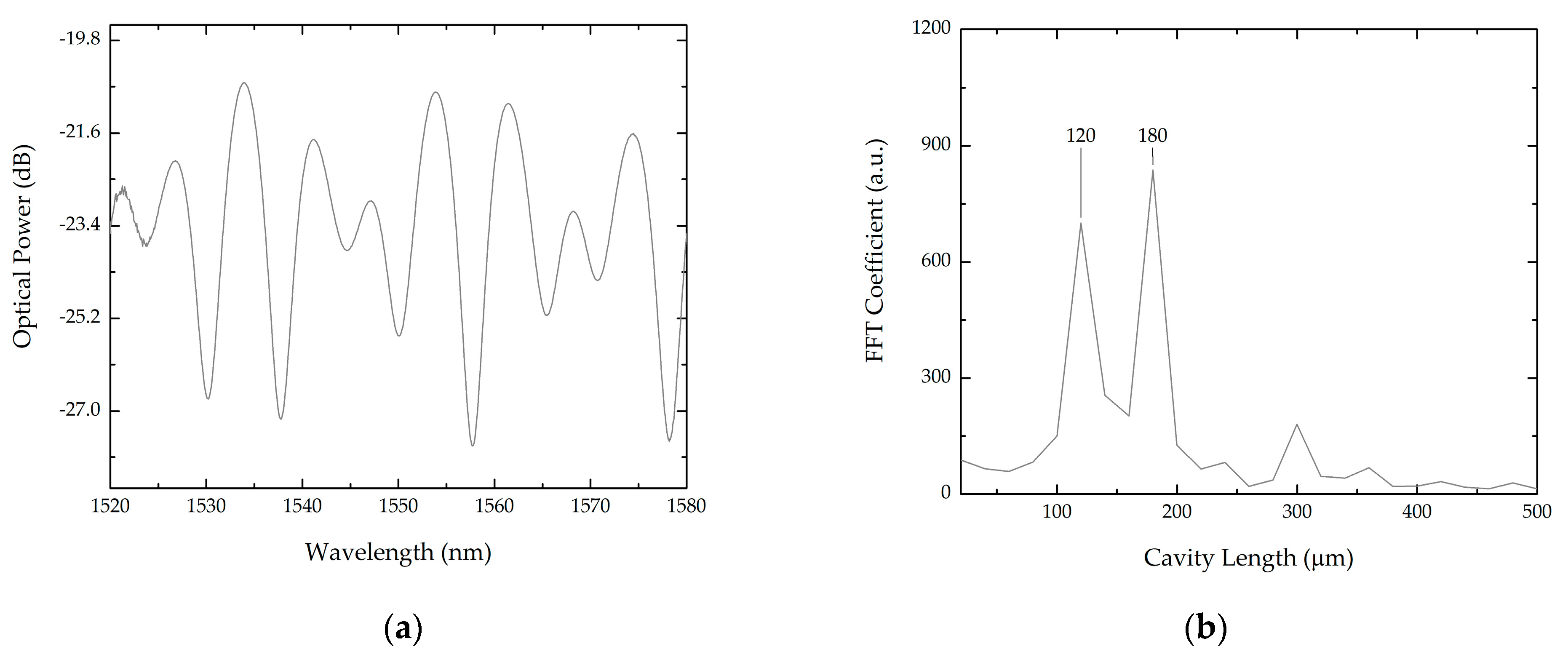
where I n represents the intensity of the reflected signal at each interface. The phase differences ϕ 1 and ϕ 2 are given by ( 4 π λ 4 n a i r d ) and ( 4 π λ n µ s p h e r e ) , respectively, with n a i r and n µ s p h e r e being the refractive index of air and microsphere respectively, d the air cavity length and δ the thickness of the microsphere silica wall. The reflected spectrum, in Figure 3a, of the fabricated hollow microsphere was acquired using a broadband optical source, an optical circulator, and an optical spectrum analyzer (OSA—Advantest Q8384) with 0.1 nm resolution, as presented in Figure 1. By performing a fast Fourier transform (FFT), it is possible to calculate the air cavity length as well as silica wall thickness. Prior to applying the FFT, the spectrum wavelength data was converted to optical frequency since the free spectral range was uniform in optical frequency but not in wavelength [33]. Seen in the FFT, in Figure 3b, two main peaks are visible. The first peak is related to the air cavity ( d ) of approximately 120 µm and the second peak is related to the cavity formed by air and silica ( d t o t a l ), of approximately 180 µm. Studying the two values, it is possible to estimate the silica wall thickness ( δ ) considering that d t o t a l n s i l i c a δ + n a i r d and assuming that the refractive index of the silica cavity is 1.444, then the silica wall thickness is δ 40   μ m . The peak corresponding to the cavity composed only by silica is not visible in the FFT signal due to low resolution provided by the short bandwidth of the optical source.

3. Results

3.1. Bilayer Deposition

3.1.1. Cleaved Fibers

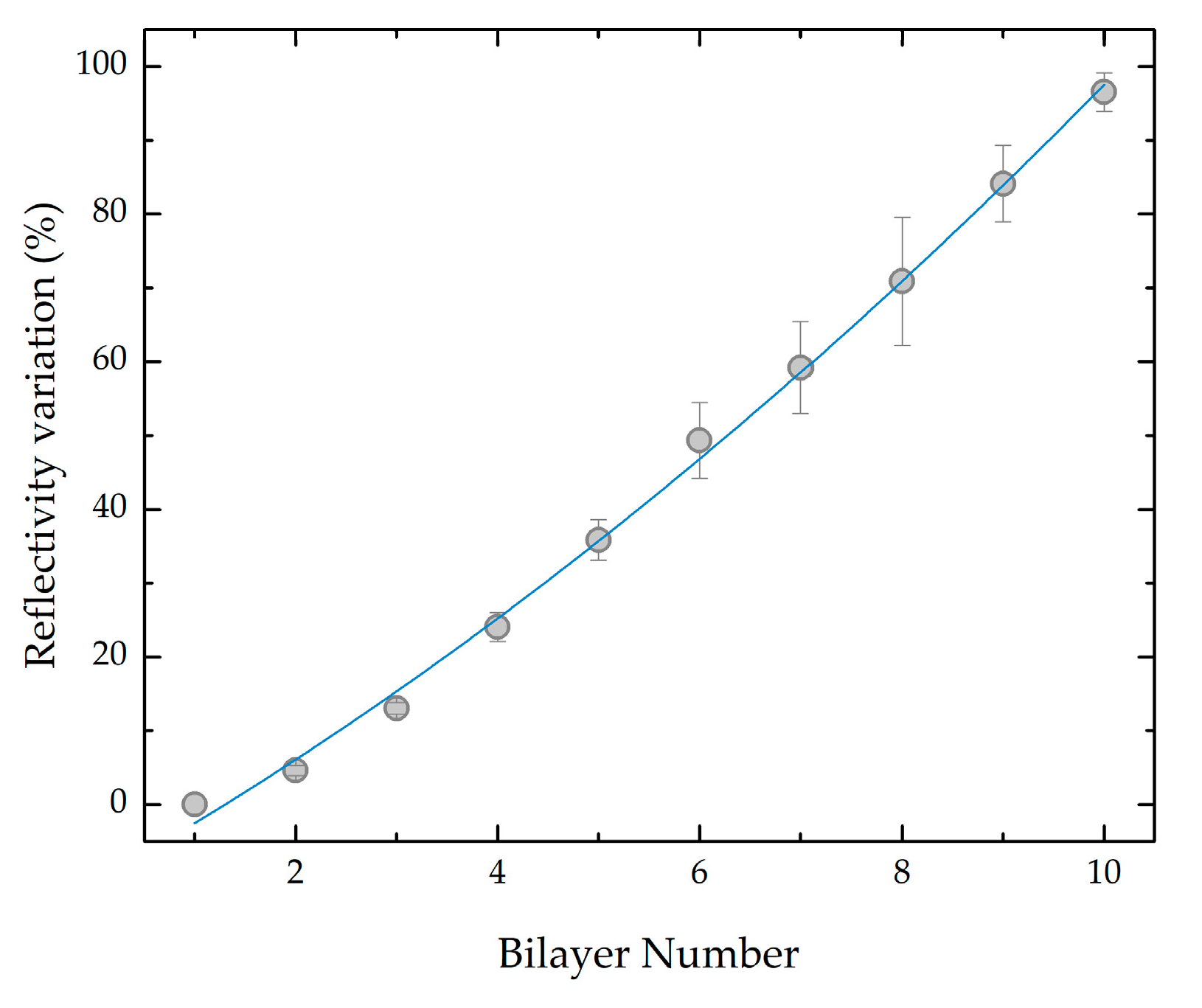
Mentioned before, bilayer adsorption kinetics was accessed by measuring the variation in surface reflectivity with the number of deposited PEI/GO bilayers in the cleaved fibers according to the deposition method previously described. Concerning the deposition of the GO layers, the fibers were immersed for 5 min. The reflected light from the cleaved fibers was measured using the experimental setup presented in Figure 1. To reference, an uncoated cleaved fiber was used to eliminate the influence of optical power fluctuations of the optical source. The coating process of the fibers was carried out simultaneously to minimize experimental errors. The mean variation of surface reflectivity with the increased number of bilayers is presented in Figure 4, where a consistent increase of the reflected optical power with the bilayer number can be observed. The increase of surface reflectivity presented some dispersion due to surface roughness variations that resulted from the cleavage process. These results also corroborate the applicability of the LbL technique to provide controlled thickness GO coatings onto an optical fiber cross-section.

3.1.2. Hollow Microspheres

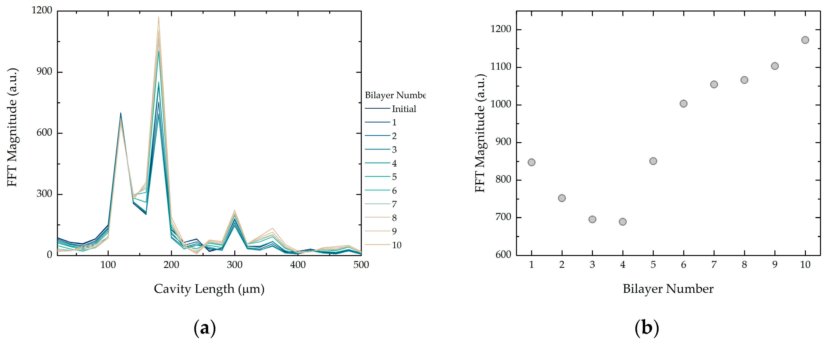
The coating process was replicated in hollow microspheres to evaluate the potential of using the LbL technique to provide GO-coated microsphere-based fiber sensing structures. Considering the complexity of the reflected spectra, the PEI/GO coating influence was studied using the FFT of the reflected signal. Shown in Figure 3b, two dominant peaks are present in the FFT signal. The first peak that corresponds to the air cavity was expected to remain constant during the coating process as no modifications were being applied in this cavity. The second peak, corresponding to the air plus silica cavity, could vary in magnitude due to variations of the outer surface reflectivity. Figure 5a shows the different FFT signals for the different bilayer numbers. Foreseen, the magnitude of peak 1 remained constant during the process. Peak 2 magnitude varied during the coating process, as shown in Figure 5b.
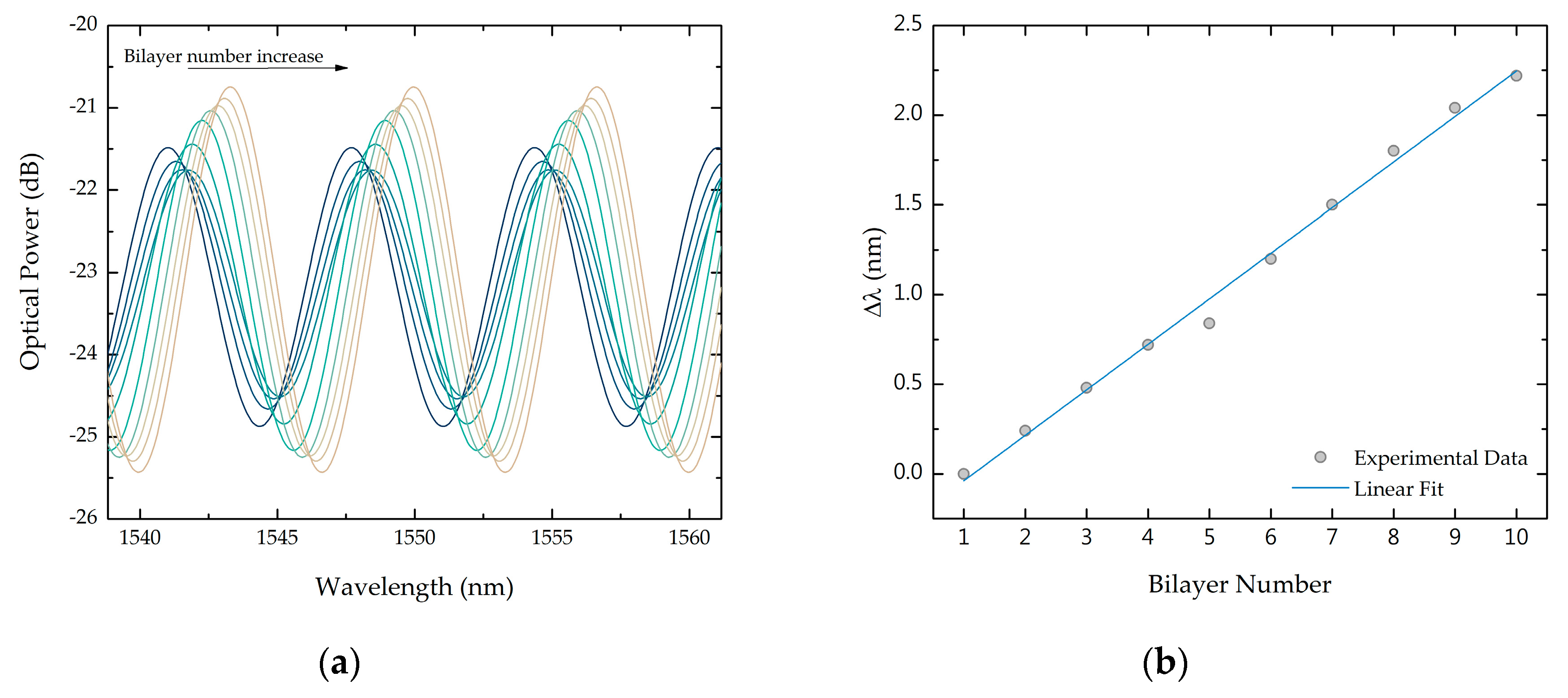
The signal component that corresponds to the air plus silica cavity can be extracted from the total reflected spectrum applying band-pass filters centered at the corresponding frequency peak. Analyzing the filtered signal that corresponds to the air plus silica cavity, it is possible to attain the influence of the PEI/GO coating on the reflectivity of the outer surface. Figure 6a shows the filtered signal associated to each bilayer number. The PEI/GO coating led to a linear wavelength shift of 254 ± 7 pm/bilayer number, shown in Figure 6b. An amplitude variation that follows a similar tendency as the FFT peak presented in Figure 5b also was attained, presenting a maximum increase of around 4 dB when compared to the filtered signal from the uncoated fiber. Considering that the filtered signal presented in Figure 6a corresponds to the component air plus silica cavity from Equation (1), one has I ( λ )   cos ( 4 π λ ( n a i r d + n m i c r o s p h e r e δ ) ) . Assuming that the component n a i r d is constant during the coating process and that thickness variations can be neglected; the signal is only dependent on refractive index variations of the outer surface. Therefore, wavelength shift is caused by a variation of the effective refractive index due to PEI/GO coating.

3.2. Graphene Oxide Adsorption Kinetics

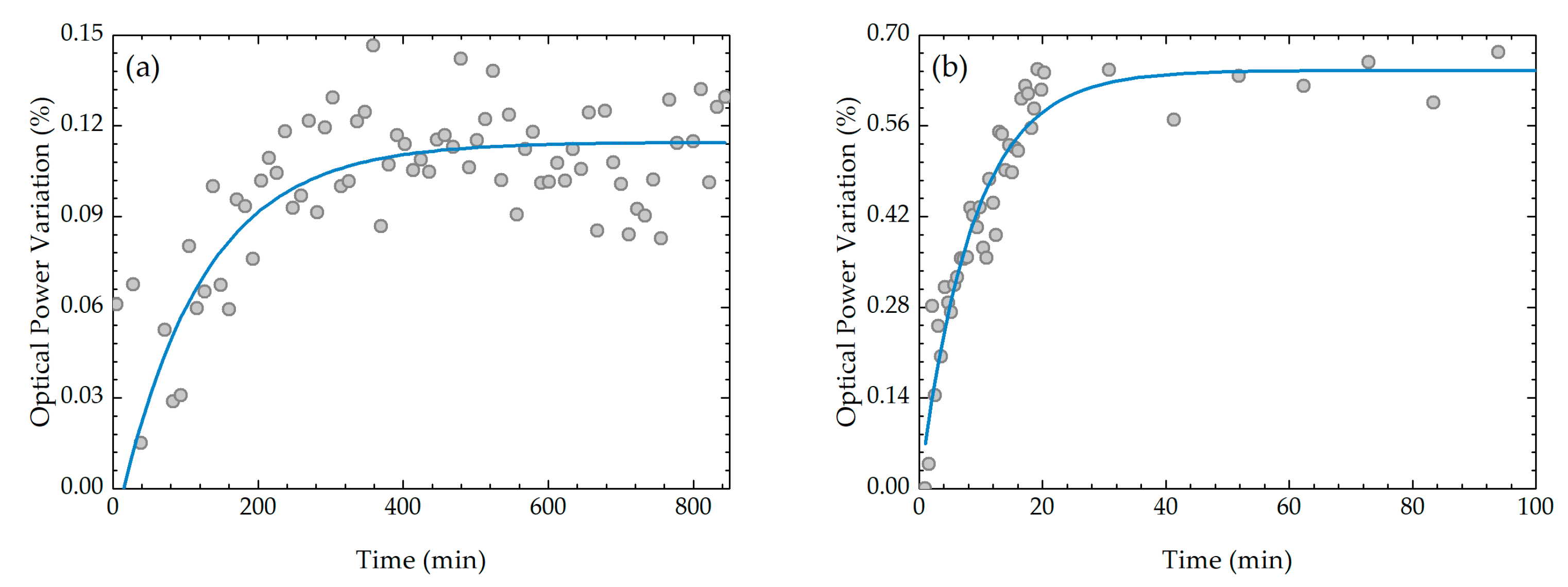
The hollow microsphere configuration also can be used to obtain the in-situ adsorption kinetics of the graphene oxide layer onto the optical fiber without and with an already adsorbed (PEI/GO)10/PEI LbL film. This is demonstrated in Figure 7, where the optical power variation is plotted as a function of adsorption time for a fiber without—Figure 7a—and with PEI/GO coating, (Figure 7b). The results are in accordance with the adsorption kinetics of polyelectrolyte molecules [34] or aggregates of molecules with an electrical charge, as in the case of liposomes [35] being the kinetic curves to be fitted by the equation:
Γ ( t ) = Γ m a x ( 1 e x p ( t τ ) ) ,
where Γ is the adsorbed amount per unit of area, Γmax is the maximum adsorbed amount per unit of area, t is the time of adsorption and τ is the characteristic time of adsorption. Calculated values from fitting with this equation reveal that adsorption characteristic times for adsorption of the GO layer is 120 ± 20 min, while for the tenth it is 10 ± 3 min.
All the fitting parameters are included in Table 1. The obtained values reveal that adsorption of the first GO layer is much slower than for the tenth GO layer, which is in accordance with the literature, specifically for the case of kinetic curves of polyaniline, a conducting polyelectrolyte whose adsorption characteristic time decreases strongly as the number of bilayers already adsorbed increases [33]. The adsorbed amount is seen to increase with the number of adsorbed bilayers already adsorbed due to an increase in surface roughness of the LbL film, as demonstrated by Ferreira et al. [36] and, therefore, also demonstrating that one cannot expect these GO films to be uniform.

4. Conclusions

Here, graphene oxide was successfully deposited in optical fibers by mounting PEI/GO layers using a LbL technique. Bilayer growth of PEI/GO LbL films onto an optical fiber end face was also successfully obtained through reflectivity measurements. Results attained from two cleaved optical fibers revealed an increase of the reflected optical power with the increased number of bilayers, up to 10 bilayers. Similarly, bilayer growth in hollow microspheres also was studied, attaining a linear wavelength shift with the increase in bilayer number. Adsorption kinetics of GO layers was successfully obtained through in-situ reflectivity measurement by placing two cleaved optical fibers coated with PEI in a solution containing GO for 15 h. This technique can be applied for easy surface reflectivity tuning for different interferometric fiber sensors, in particular ones with complex geometries. Finally, we also demonstrated that one can achieve, by this method, the in situ adsorption kinetic curves of GO layers, meaning that this method can be applied to other molecules.

Author Contributions

Investigation, C.S.M.; writing—original draft preparation, C.S.M.; writing—review and editing, M.R., P.A.R.; supervision, S.O.S. and O.F. All authors have read and agreed to the published version of the manuscript.

Funding

C.S. Monteiro was financed by FCT—Portuguese national funding agency for science, research and technology (SFRH/BD/135820/2018). This work is financed by National Funds through the Portuguese funding agency, FCT—Fundação para a Ciência e a Tecnologia within projects UID/EEA/50014/2019, UID/FIS/00068/2019 and M-ERA-NET2/0002/2016.

Acknowledgments

In this section you can acknowledge any support given which is not covered by the author contribution or funding sections. This may include administrative and technical support, or donations in kind (e.g., materials used for experiments).

Conflicts of Interest

The authors declare no conflict of interest.

References

  1. Geim, A.K.; Novoselov, K.S. The rise of graphene. Nat. Mater. 2007, 6, 183–191. [Google Scholar] [CrossRef]
  2. Zhu, Y.; Murali, S.; Cai, W.; Li, X.; Suk, J.W.; Potts, J.R.; Ruoff, R.S. Graphene and graphene oxide: Synthesis, properties, and applications. Adv. Mater. 2010, 22, 3906–3924. [Google Scholar] [CrossRef]
  3. Britnell, L.; Gorbachev, R.V.; Jalil, R.; Belle, B.D.; Schedin, F.; Mishchenko, A.; Georgiou, T.; Katsnelson, M.I.; Eaves, L.; Morozov, S.V.; et al. Field-effect tunneling transistor based on vertical graphene heterostructures. Science 2012, 335, 947–950. [Google Scholar] [CrossRef] [PubMed] [Green Version]
  4. Xuesong, L.; Yanwu, Z.; Weiwei, C.; Mark, B.; Boyang, H.; David, C.; Richard, P. Transfer of Large-Area Graphene Films for High-Performance Transparent Conductive Electrodes. Nano Lett. 2009, 9, 4359–4363. [Google Scholar]
  5. Wang, X.; Zhi, L.; Müllen, K. Transparent, conductive graphene electrodes for dye-sensitized solar cells. Nano Lett. 2008, 8, 323–327. [Google Scholar] [CrossRef] [PubMed]
  6. He, Q.; Wu, S.; Yin, Z.; Zhang, H. Graphene-based electronic sensors. Chem. Sci. 2012, 3, 1764. [Google Scholar] [CrossRef] [Green Version]
  7. Gerasimov, G. Graphene-Based Gas Sensors. J. Mater. Chem. A 2013, 1, 10078–10091. [Google Scholar] [CrossRef]
  8. Marcano, D.C.; Kosynkin, D.V.; Berlin, J.M.; Sinitskii, A.; Sun, Z.; Slesarev, A.; Alemany, L.B.; Lu, W.; Tour, J.M. Improved Synthesis of Graphene Oxide. ACS Nano 2010, 4, 4806–4814. [Google Scholar] [CrossRef]
  9. Brodie, B.C. On the Atomic Weight of Graphite. Philos. Trans. R. Soc. A Math. Phys. Eng. Sci. 1859, 149, 249–259. [Google Scholar]
  10. Staudenmaier, L. Procedure for the preparation of graphitic acid. Ber Dtsch. Chem. Ges. 1899, 32, 1394–1399. [Google Scholar] [CrossRef] [Green Version]
  11. Hummers, W.S.; Offeman, R.E. Preparation of Graphitic Oxide. J. Am. Chem. Soc. 1958, 80, 1339. [Google Scholar] [CrossRef]
  12. Mkhoyan, K.A.; Contryman, A.W.; Silcox, J.; Stewart, D.A.; Eda, G.; Mattevi, C.; Miller, S.; Chhowalla, M. Atomic and electronic structure of graphene-oxide. Nano Lett. 2009, 9, 1058–1063. [Google Scholar] [CrossRef] [PubMed] [Green Version]
  13. Culshaw, B.; Kersey, A. Fiber-optic sensing: A historical perspective. J. Lightwave Technol. 2008, 26, 1064–1078. [Google Scholar] [CrossRef]
  14. Wu, Y.; Yao, B.; Zhang, A.; Rao, Y.; Wang, Z.; Cheng, Y.; Gong, Y.; Zhang, W.; Chen, Y.; Chiang, K.S. Graphene-coated microfiber Bragg grating for high-sensitivity gas sensing. Opt. Lett. 2014, 39, 1235. [Google Scholar] [CrossRef] [PubMed]
  15. Yu, C.; Wu, Y.; Liu, X.; Fu, F.; Gong, Y.; Rao, Y.-J.; Chen, Y. Miniature fiber-optic NH3 gas sensor based on Pt nanoparticle-incorporated graphene oxide. Sens. Actuators B Chem. 2017, 244, 107–113. [Google Scholar] [CrossRef]
  16. Zhang, H.; Kulkarni, A.; Kim, H.; Woo, D.; Kim, Y.-J.; Hong, B.H.; Choi, J.-B.; Kim, T. Detection of Acetone Vapor Using Graphene on Polymer Optical Fiber. J. Nanosci. Nanotechnol. 2011, 11, 5939–5943. [Google Scholar] [CrossRef]
  17. Hernaez, M.; Mayes, A.G.; Melendi-Espina, S. Graphene oxide in lossy mode resonance-based optical fiber sensors for ethanol detection. Sensors 2018, 18, 58. [Google Scholar] [CrossRef] [Green Version]
  18. Sharma, A.K.; Gupta, J. Graphene based chalcogenide fiber-optic evanescent wave sensor for detection of hemoglobin in human blood. Opt. Fiber Technol. 2018, 41, 125–130. [Google Scholar] [CrossRef]
  19. Divagar, M.; Gowri, A.; John, S.; Sai, V.V.R. Graphene oxide coated U-bent plastic optical fiber based chemical sensor for organic solvents. Sens. Actuators B Chem. 2018, 262, 1006–1012. [Google Scholar] [CrossRef]
  20. Wang, Y.; Shen, C.; Lou, W.; Shentu, F.; Zhong, C.; Dong, X.; Tong, L. Fiber optic relative humidity sensor based on the tilted fiber Bragg grating coated with graphene oxide. Appl. Phys. Lett. 2016, 109, 1–6. [Google Scholar] [CrossRef]
  21. Ma, J.; Jin, W.; Ho, H.L.; Dai, J.Y. High-sensitivity fiber-tip pressure sensor with graphene diaphragm. Opt. Lett. 2012, 37, 2493. [Google Scholar] [CrossRef] [Green Version]
  22. Li, C.; Liu, Q.; Peng, X.; Fan, S. Analyzing the temperature sensitivity of Fabry-Perot sensor using multilayer graphene diaphragm. Opt. Express 2015, 23, 27494. [Google Scholar] [CrossRef] [PubMed]
  23. Ma, J.; Xuan, H.; Ho, H.L.; Jin, W.; Yang, Y.; Fan, S. Fiber-optic fabry-pérot acoustic sensor with multilayer graphene diaphragm. IEEE Photonics Technol. Lett. 2013, 25, 932–935. [Google Scholar] [CrossRef]
  24. Xu, M.G.; Dakin, J.P. Novel hollow-glass microsphere sensor for monitoring high hydrostatic pressure. In Fiber Optic and Laser Sensors X; SPIE: Boston, MA, USA, 1993; Volume 1795, pp. 2–7. [Google Scholar]
  25. Martins, J.; Diaz, C.A.R.; Domingues, M.F.; Ferreira, R.A.S.; Antunes, P.; Andre, P.S. Low-Cost and High-Performance Optical Fiber-Based Sensor for Liquid Level Monitoring. IEEE Sens. J. 2019, 19, 4882–4888. [Google Scholar] [CrossRef]
  26. Novais, S.; Ferreira, M.S.; Pinto, J.L. Lateral Load Sensing with an Optical Fiber Inline Microcavity. IEEE Photonics Technol. Lett. 2017, 29, 1502–1505. [Google Scholar] [CrossRef]
  27. Liu, S.; Yang, K.; Wang, Y.; Qu, J.; Liao, C.; He, J.; Li, Z.; Yin, G.; Sun, B.; Zhou, J.; et al. High-sensitivity strain sensor based on in-fiber rectangular air bubble. Sci. Rep. 2015, 5, 7624. [Google Scholar] [CrossRef] [Green Version]
  28. Monteiro, C.; Silva, S.; Frazao, O. Hollow Microsphere Fabry–Perot Cavity for Sensing Applications. IEEE Photonics Technol. Lett. 2017, 29, 1229–1232. [Google Scholar] [CrossRef] [Green Version]
  29. Oliveira, O.N., Jr.; Raposo, M.; Dhanabalan, A. Langmuir-Blodgett (LB) and Self-assembled (SA) polymeric films. In Handbook of Surfaces and Interfaces of Materials; Nalwa, S., Ed.; Academic Press: New York, NY, USA, 2001; pp. 1–63. [Google Scholar]
  30. Keeney, M.; Jiang, X.Y.; Yamane, M.; Lee, M.; Goodman, S.; Yang, F. Nanocoating for biomolecule delivery using layer-by-layer self-assembly. J. Mater. Chem. B 2015, 3, 8757–8770. [Google Scholar] [CrossRef] [Green Version]
  31. Monteiro, C.S.; Kobelke, J.; Schuster, K.; Bierlich, J.; Silva, S.O.; Frazão, O. High sensitivity strain sensor based on twin hollow microspheres. Microw. Opt. Technol. Lett. 2019, 61, 454–458. [Google Scholar] [CrossRef]
  32. Liao, C.; Liu, S.; Xu, L.; Wang, C.; Wang, Y.; Li, Z.; Wang, Q.; Wang, D.N. Sub-micron silica diaphragm-based fiber-tip Fabry–Perot interferometer for pressure measurement. Opt. Lett. 2014, 39, 2827. [Google Scholar] [CrossRef] [Green Version]
  33. Warren-Smith, S.C.; André, R.M.; Perrella, C.; Dellith, J.; Bartelt, H. Direct core structuring of microstructured optical fibers using focused ion beam milling. Opt. Express 2016, 24, 378. [Google Scholar] [CrossRef] [PubMed]
  34. Raposo, M.; Pontes, R.S.; Mattoso, L.H.C.; Oliveira, O.N. Kinetics of adsorption of poly(o-methoxyaniline) self-assembled films. Macromolecules 1997, 30, 6095–6101. [Google Scholar] [CrossRef]
  35. Duarte, A.A.; Filipe, S.L.; Abegão, L.M.G.; Gomes, P.J.; Ribeiro, P.A.; Raposo, M. Adsorption kinetics of DPPG liposome layers: A quantitative analysis of surface roughness. Microsc. Microanal. 2013, 19, 867–875. [Google Scholar] [CrossRef] [PubMed]
  36. Ferreira, Q.; António Ribeiro, P.; Raposo, M. Villain’s fractal growth of poly[1-[4-(3-carboxy-4-hydroxyphenylazo) benzenesulfonamido]-1,2-ethanediyl, sodium salt] J-aggregates onto layer-by-layer films and its effect on film absorbance spectrum. J. Appl. Phys. 2013, 113. [Google Scholar] [CrossRef]
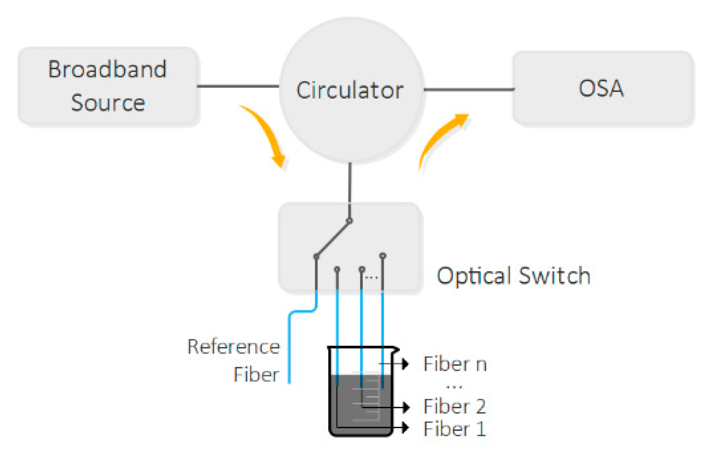
Figure 1. GO adsorption kinetics experimental setup.
Photonics 07 00011 g001
Figure 2. Microscope image of the fabricated hollow microsphere.
Photonics 07 00011 g002
Figure 3. (a) Reflected spectrum of the fabricated hollow microsphere and (b) corresponding FFT.
Photonics 07 00011 g003
Figure 4. Reflectivity variation with the number of PEI/GO bilayers, for the cleaved fibers.
Photonics 07 00011 g004
Figure 5. (a) FFT signals for each bilayer number; (b) Peak 2 magnitude value, for each bilayer number.
Photonics 07 00011 g005
Figure 6. (a) Filtered signal corresponding to peak 2; (b) Wavelength shift of the peaks.
Photonics 07 00011 g006
Figure 7. In-situ adsorption kinetics of a layer of graphene oxide onto a (a) optical fiber and (b) (PEI/GO)10/PEI LbL film already adsorbed on the optical fiber.
Photonics 07 00011 g007
Table 1. Fitting parameters of GO adsorption kinetics. R is the correlation coefficient.
First GO LayerTenth GO Layer
Γ m a x (%)0.0013 ± 0.00050.0055 ± 0.0005
τ (min)120 ± 2010 ± 3
R0.870.93